WO2017131118A1 - Câble à fibres optiques - Google Patents
Câble à fibres optiques Download PDFInfo
- Publication number
- WO2017131118A1 WO2017131118A1 PCT/JP2017/002814 JP2017002814W WO2017131118A1 WO 2017131118 A1 WO2017131118 A1 WO 2017131118A1 JP 2017002814 W JP2017002814 W JP 2017002814W WO 2017131118 A1 WO2017131118 A1 WO 2017131118A1
- Authority
- WO
- WIPO (PCT)
- Prior art keywords
- optical fiber
- cores
- slot
- optical
- fiber cable
- Prior art date
- Legal status (The legal status is an assumption and is not a legal conclusion. Google has not performed a legal analysis and makes no representation as to the accuracy of the status listed.)
- Ceased
Links
Images


Classifications
-
- G—PHYSICS
- G02—OPTICS
- G02B—OPTICAL ELEMENTS, SYSTEMS OR APPARATUS
- G02B6/00—Light guides; Structural details of arrangements comprising light guides and other optical elements, e.g. couplings
- G02B6/44—Mechanical structures for providing tensile strength and external protection for fibres, e.g. optical transmission cables
- G02B6/4401—Optical cables
- G02B6/441—Optical cables built up from sub-bundles
-
- G—PHYSICS
- G02—OPTICS
- G02B—OPTICAL ELEMENTS, SYSTEMS OR APPARATUS
- G02B6/00—Light guides; Structural details of arrangements comprising light guides and other optical elements, e.g. couplings
- G02B6/44—Mechanical structures for providing tensile strength and external protection for fibres, e.g. optical transmission cables
-
- G—PHYSICS
- G02—OPTICS
- G02B—OPTICAL ELEMENTS, SYSTEMS OR APPARATUS
- G02B6/00—Light guides; Structural details of arrangements comprising light guides and other optical elements, e.g. couplings
- G02B6/44—Mechanical structures for providing tensile strength and external protection for fibres, e.g. optical transmission cables
- G02B6/4401—Optical cables
- G02B6/4403—Optical cables with ribbon structure
-
- G—PHYSICS
- G02—OPTICS
- G02B—OPTICAL ELEMENTS, SYSTEMS OR APPARATUS
- G02B6/00—Light guides; Structural details of arrangements comprising light guides and other optical elements, e.g. couplings
- G02B6/44—Mechanical structures for providing tensile strength and external protection for fibres, e.g. optical transmission cables
- G02B6/4401—Optical cables
- G02B6/4407—Optical cables with internal fluted support member
-
- G—PHYSICS
- G02—OPTICS
- G02B—OPTICAL ELEMENTS, SYSTEMS OR APPARATUS
- G02B6/00—Light guides; Structural details of arrangements comprising light guides and other optical elements, e.g. couplings
- G02B6/44—Mechanical structures for providing tensile strength and external protection for fibres, e.g. optical transmission cables
- G02B6/4479—Manufacturing methods of optical cables
- G02B6/4489—Manufacturing methods of optical cables of central supporting members of lobe structure
-
- G—PHYSICS
- G02—OPTICS
- G02B—OPTICAL ELEMENTS, SYSTEMS OR APPARATUS
- G02B6/00—Light guides; Structural details of arrangements comprising light guides and other optical elements, e.g. couplings
- G02B6/44—Mechanical structures for providing tensile strength and external protection for fibres, e.g. optical transmission cables
- G02B6/4401—Optical cables
- G02B6/4407—Optical cables with internal fluted support member
- G02B6/4409—Optical cables with internal fluted support member for ribbons
-
- G—PHYSICS
- G02—OPTICS
- G02B—OPTICAL ELEMENTS, SYSTEMS OR APPARATUS
- G02B6/00—Light guides; Structural details of arrangements comprising light guides and other optical elements, e.g. couplings
- G02B6/44—Mechanical structures for providing tensile strength and external protection for fibres, e.g. optical transmission cables
- G02B6/4401—Optical cables
- G02B6/4429—Means specially adapted for strengthening or protecting the cables
- G02B6/4434—Central member to take up tensile loads
Definitions
- the present invention relates to an optical fiber cable.
- This application claims priority based on Japanese Patent Application No. 2016-014480 filed on Jan. 28, 2016, and incorporates all the contents described in the above Japanese application.
- Patent Document 1 a plurality of optical fiber ribbons in which a plurality of optical fiber cores are arranged in parallel, and an SZ shape for accommodating one or a plurality of the optical fiber ribbons are formed.
- An optical fiber cable comprising a slot rod having a plurality of slot grooves, an upper winding tape wound around the slot rod, and a jacket covering the outside of the slot rod covered with the upper winding tape is described. ing.
- Patent Document 2 describes a slotless optical fiber cable having no slot rod.
- An optical fiber cable includes an optical unit having a plurality of optical fiber ribbons; A slot rod having a plurality of slot grooves in which the optical unit is stored; A cable jacket covering the outside of the slot rod; and an optical fiber cable comprising:
- the optical fiber ribbon is a connecting portion in which a plurality of optical fiber cores are arranged in parallel and a part or all of the optical fiber cores are connected between adjacent optical fiber cores. And an unconnected portion that is not connected between adjacent optical fiber core wires is intermittently provided in the longitudinal direction,
- the outer diameter is 35 mm or less, and the number of optical fiber cores in the optical unit housed in one slot groove is 100 or more.
- the slotless type optical fiber cable Since the slotless type optical fiber cable has no slot rod, the density of the optical fiber core to be accommodated can be increased compared to the slot type optical fiber cable. However, as the number of optical fiber cores increases, there is a problem in the discriminability of identifying the optical fiber tape cores when taking out the optical fiber tape cores at the time of intermediate branching of the optical fiber cable. On the other hand, the slot type optical fiber cable can take out the optical fiber tape core wire for each slot groove, so that the optical fiber tape core wire has good discrimination, but the member that forms the slot rod is in the cable. It is difficult to increase the density.
- an object of the present disclosure is to provide an optical fiber cable capable of mounting optical fiber core wires at high density in a slot-type multi-core optical fiber cable.
- An optical fiber cable according to an embodiment of the present invention, (1) an optical unit having a plurality of optical fiber ribbons; A slot rod having a plurality of slot grooves in which the optical unit is stored; A cable jacket covering the outside of the slot rod; and an optical fiber cable comprising:
- the optical fiber ribbon is a connecting portion in which a plurality of optical fibers are arranged in parallel and a part or all of the optical fibers are connected between adjacent optical fibers.
- an unconnected portion that is not connected between adjacent optical fiber core wires is intermittently provided in the longitudinal direction,
- the outer diameter is 35 mm or less, and the number of optical fiber cores in the optical unit housed in one slot groove is 100 or more.
- the optical fiber cable of the above (1) is an intermittently connected type in which the optical fiber tape core wire is intermittently provided with the connecting portion and the non-connecting portion, the optical fiber tape is bent when the optical fiber cable is bent.
- the distortion generated in the core wire can be alleviated and the deterioration of the transmission characteristics can be prevented.
- a plurality of such intermittently connected optical fiber ribbons are combined into an optical unit, the density can be increased without deteriorating the transmission characteristics, and even if the outer diameter is 35 mm or less, 1
- the number of optical fiber cores in the optical unit housed in one slot groove can be 100 or more. Therefore, the optical fiber core wire can be mounted at a high density in a slot-type multi-core optical fiber cable with good discrimination of the optical fiber tape core wire.
- the density of the number of the optical fiber cores included in the optical fiber cable is 2.4 cores / mm 2 or more in the cross section of the optical fiber cable.
- the density of the number of the optical fibers contained in the optical fiber cable can be 2.4 cores / mm 2 or more in the cross section of the optical fiber cable. Even a slot type optical fiber cable can mount a large number of optical fiber core wires at high density.
- the optical unit includes a plurality of subunits in a state where the optical fiber ribbon is twisted. Since the optical fiber ribbon is housed in a twisted state for each subunit, the discriminability when taking out the optical fiber ribbon is improved.
- a bundle material is wound around the subunit. Since a bundle for identification is wound around the subunit, the subunit can be easily identified.
- FIG. 1 is a cross-sectional view showing an example of an optical fiber cable according to the present embodiment.
- FIG. 2 is a plan view of a 12-core intermittently connected optical fiber ribbon.
- FIG. 3 is a schematic diagram of subunits in the optical unit of the optical fiber cable according to the present embodiment.
- an optical fiber cable 1 includes an optical unit 2 (an assembly of subunits 7), a slot rod 4 having a plurality of slot grooves 3 in which the optical unit 2 is accommodated, and an outside of the slot rod 4.
- the slot rod 4 is provided with a tension member 6 at the center, and is provided with a plurality of slot grooves 3 (six in the example of FIG. 1) radially arranged by unidirectional twisting or SZ twisting on the outer surface side. It has a structure.
- the optical unit 2 has a plurality of optical fiber ribbons 10. As shown in FIG. 2, the optical fiber ribbon 10 has a plurality (12 in the example of FIG. 2) of optical fibers 11A to 11L arranged in parallel. These optical fiber core wires 11A to 11L are single-core coated optical fibers. The optical fiber cores 11A to 11L may be coated with different colors so that the optical fiber cores can be distinguished from each other.
- the optical fiber ribbon 10 is an intermittently connected optical fiber ribbon, and in a state where a plurality of optical fibers are arranged in parallel, a connecting portion 12 in which adjacent optical fibers are connected to each other;
- the non-connecting portion 13 where the adjacent optical fiber cores are not connected is intermittently provided in the longitudinal direction.
- the location where the connecting portion 12 and the non-connecting portion 13 are provided intermittently may be between some optical fiber cores as shown in FIG. 2, or all optical fibers. It may be between core wires.
- the unconnected portion 13 is not provided between the optical fiber core wires 11A and 11B, 11C and 11D, 11E and 11F, 11G and 11H, 11I and 11J, and 11K and 11L.
- the optical fiber ribbon 10 is formed by intermittently applying a connecting resin such as an ultraviolet curable resin or a thermosetting resin between the optical fibers to intermittently connect the connecting portion 12 and the non-connecting portion 13. It may be produced as follows.
- the said connection resin is good also as resin with good peelability, in order to make the operation
- a connecting resin to the plurality of optical fiber cores 11A to 11L, connecting all the optical fiber core wires, and then cutting a part with a rotary blade or the like to make the unconnected portion 13, The intermittently connected optical fiber ribbon 10 may be manufactured.
- the optical fiber cable 1 has an outer diameter of 35 mm or less, and the number of optical fiber cores in the optical unit 2 housed in one slot groove 3 is 100 or more.
- the optical fiber ribbon 10 is not connected between the connecting portion 12 where the adjacent optical fibers are connected and the adjacent optical fibers. It is an intermittently connected type in which the connecting portion 13 is provided intermittently in the longitudinal direction. Thereby, when the optical fiber cable 1 is bent, the distortion which generate
- the number of optical fiber cores in the accommodated optical unit 2 can be 100 or more.
- the optical fiber core wire can be mounted at a high density in the slot-type multi-core optical fiber cable with good discrimination of the optical fiber tape core wire 10.
- the optical fiber cable 1 according to the present embodiment is particularly suitable for a multi-core cable having 1000 cores or more.
- the density of the number of cores of the optical fiber core contained in the optical fiber cable 1 is 2.4 cores / mm 2 or more in the cross section of the optical fiber cable 1. .
- the density of the number of the optical fiber cores can be made 2.4 cores / mm 2 or more. Can be mounted with high density.
- the optical unit 2 may be provided with a plurality of subunits 7 (see FIG. 3) in a state where the optical fiber ribbon 10 is twisted.
- the subunit 7 is provided in a state where six optical fiber ribbons 10 are twisted together. As described above, since the optical fiber ribbon 10 is housed in a state of being twisted for each subunit 7, the discriminability when the optical fiber ribbon 10 is taken out is improved.
- the bundle material 8 may be wound around the subunit 7. Since the bundle material 8 is wound around the subunit 7, the subunit 7 can be easily identified. In addition, it is also possible to improve discrimination by changing the color of the bundle material 8.
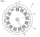
- FIG. 4 is a cross-sectional view showing an example of a conventional slot-type optical fiber cable.
- Example 1 Two pieces of the 12-fiber intermittently connected optical fiber tape cores 10 shown in FIG. 2 were used and twisted at a twist pitch of 500 mm using a twisting facility to form a 72-fiber subunit 7. Then, by using the collecting machine, four subunits 7 formed as described above are stored in the six slot grooves 3 of the slot type optical fiber cable 1 shown in FIG. An optical fiber cable was produced. Note that the twisting of the optical fiber ribbon 10 and the storing in the slot groove 3 may be performed in the same process. The twist direction of the slot groove 3 may be unidirectional twist or SZ twist.
- Example 2 In Example 2, a 3456-core optical fiber cable was produced in the same manner as in Example 1 except that eight subunits 7 were housed in each slot groove 3.
- the optical fiber cable 101 uses a total of 125 optical fiber ribbons 102 having eight optical fibers that are connected in parallel (not intermittently connected).
- the optical fiber cable 101 includes a slot rod 104 having 13 slot grooves 103 in which a plurality of optical fiber ribbons 102 (10 or 5) are accommodated. Furthermore, a cable jacket 105 that covers the outside of the slot rod 104 and a tension member 106 provided at the center are provided.
- the number of optical fiber cores accommodated in one slot groove 103 is 80 or less.
- the outer diameter of the optical fiber cable 101 of the comparative example is 23.5 mm, and the core density (number of cores / cable cross-sectional area) of the optical fiber per unit area in the cable cross section is 2.3 cores / mm 2 .
- the core density of the optical fiber per unit area in the 1728 optical fiber cable of Example 1 is 3.3 cores / mm 2 .
- the core density of the optical fiber core wire per unit area in the 3456 core optical fiber cable of Example 2 is 3.8 cores / mm 2 .
- the core density of the optical fiber per unit area can be increased as compared with the conventional optical fiber cable 101 (comparative example). Note that if the optical fiber has an excessively high core density, transmission characteristics deteriorate, so the upper limit is preferably about 7 cores / mm 2 .
- the optical fiber cable 101 of the comparative example uses the connected optical fiber tape core wire, the number of cores in one groove cannot be increased. Moreover, since the optical fiber tape core wire in the slot groove can be identified by increasing the number of slot grooves of the slot rod, the ratio of the slot rod to the space in the cable increases. For this reason, the ratio (slot occupation ratio) that the slot rod 104 occupies the space in the cable is 38.5%. On the other hand, since Examples 1 and 2 use intermittently connected optical fiber ribbons, the number of cores in one slot groove can be increased. In addition, the intermittently connected optical fiber ribbon can be easily deformed, and can be packed by increasing the cross-sectional area of the slot groove. For this reason, the slot occupation ratio can be reduced to 25.7%. Since the optical fiber core wire can be mounted at a higher density as the slot occupation ratio is smaller, the structure of the optical fiber cable 1 of the first and second embodiments is suitable for the high-density mounting and has the above-described core density. Can do.
- the individual optical fiber core wires can be compared with the configuration without the subunits. Discriminability can be improved.
Landscapes
- Physics & Mathematics (AREA)
- General Physics & Mathematics (AREA)
- Optics & Photonics (AREA)
- Engineering & Computer Science (AREA)
- Manufacturing & Machinery (AREA)
- Optical Fibers, Optical Fiber Cores, And Optical Fiber Bundles (AREA)
- Light Guides In General And Applications Therefor (AREA)
Abstract
Priority Applications (3)
| Application Number | Priority Date | Filing Date | Title |
|---|---|---|---|
| EP17744348.8A EP3410168A4 (fr) | 2016-01-28 | 2017-01-26 | Câble à fibres optiques |
| US15/771,642 US10268009B2 (en) | 2016-01-28 | 2017-01-26 | Optical fiber cable |
| JP2017563830A JP6958361B2 (ja) | 2016-01-28 | 2017-01-26 | 光ファイバケーブル |
Applications Claiming Priority (2)
| Application Number | Priority Date | Filing Date | Title |
|---|---|---|---|
| JP2016-014480 | 2016-01-28 | ||
| JP2016014480 | 2016-01-28 |
Publications (1)
| Publication Number | Publication Date |
|---|---|
| WO2017131118A1 true WO2017131118A1 (fr) | 2017-08-03 |
Family
ID=59399062
Family Applications (1)
| Application Number | Title | Priority Date | Filing Date |
|---|---|---|---|
| PCT/JP2017/002814 Ceased WO2017131118A1 (fr) | 2016-01-28 | 2017-01-26 | Câble à fibres optiques |
Country Status (4)
| Country | Link |
|---|---|
| US (1) | US10268009B2 (fr) |
| EP (1) | EP3410168A4 (fr) |
| JP (1) | JP6958361B2 (fr) |
| WO (1) | WO2017131118A1 (fr) |
Cited By (2)
| Publication number | Priority date | Publication date | Assignee | Title |
|---|---|---|---|---|
| EP3819691A4 (fr) * | 2018-07-03 | 2022-03-30 | Nippon Telegraph And Telephone Corporation | Câble de fibre optique, et dispositif et procédé de fabrication de câble de fibre optique |
| JP2023073421A (ja) * | 2019-01-10 | 2023-05-25 | 古河電気工業株式会社 | 光ファイバケーブル、ケーブルコアの製造方法 |
Families Citing this family (7)
| Publication number | Priority date | Publication date | Assignee | Title |
|---|---|---|---|---|
| JP2017142285A (ja) * | 2016-02-08 | 2017-08-17 | 住友電気工業株式会社 | 光ファイバケーブル |
| US11194108B2 (en) * | 2017-06-14 | 2021-12-07 | Sumitomo Electric Industries, Ltd. | Slot-type optical cable |
| EP4279966A3 (fr) | 2017-08-08 | 2024-03-06 | Corning Research & Development Corporation | Ruban de fibre optique enroulable à faible atténuation, fibre optique à grand diamètre de champ de mode et câble |
| CN110989118B (zh) * | 2019-12-27 | 2020-12-25 | 四川天邑康和通信股份有限公司 | 一种自承式集束成型蝶形光缆 |
| CN111007613B (zh) * | 2019-12-27 | 2021-04-27 | 四川天邑康和通信股份有限公司 | 一种集束成型蝶形光缆 |
| EP4246195A4 (fr) * | 2020-11-11 | 2024-04-24 | Sumitomo Electric Industries, Ltd. | Câble à fibres optiques |
| WO2023282284A1 (fr) * | 2021-07-07 | 2023-01-12 | 住友電気工業株式会社 | Câble à fibre optique de type à fente |
Citations (9)
| Publication number | Priority date | Publication date | Assignee | Title |
|---|---|---|---|---|
| JPH07146426A (ja) * | 1993-11-24 | 1995-06-06 | Fujikura Ltd | 防水型光ファイバケーブル |
| EP0996016A2 (fr) * | 1998-10-23 | 2000-04-26 | Bowthorpe Plc | Câble à fibres optiques |
| JP2000131580A (ja) * | 1998-10-23 | 2000-05-12 | Sumitomo Electric Ind Ltd | 光ケーブルの製造方法、及び、光ケーブルから光ファイバを取り出す方法 |
| JP2010008923A (ja) | 2008-06-30 | 2010-01-14 | Nippon Telegr & Teleph Corp <Ntt> | 光ファイバケーブル |
| JP2014211511A (ja) | 2013-04-18 | 2014-11-13 | 住友電気工業株式会社 | 光ケーブル |
| JP2015052692A (ja) * | 2013-09-06 | 2015-03-19 | 住友電気工業株式会社 | 光ケーブル |
| JP2015099314A (ja) * | 2013-11-20 | 2015-05-28 | 株式会社フジクラ | スロット型光ファイバケーブル |
| JP2015215447A (ja) * | 2014-05-09 | 2015-12-03 | 株式会社フジクラ | 光ファイバケーブル |
| JP2016014480A (ja) | 2015-08-31 | 2016-01-28 | 株式会社ジェイテクト | 動力伝達軸の製造方法 |
Family Cites Families (16)
| Publication number | Priority date | Publication date | Assignee | Title |
|---|---|---|---|---|
| JP3001117B2 (ja) * | 1990-05-28 | 2000-01-24 | 日本電信電話株式会社 | 光ケーブルとその製造方法 |
| JPH10319284A (ja) * | 1997-05-21 | 1998-12-04 | Sumitomo Electric Ind Ltd | スペーサ型光ファイバケーブル |
| US6304701B1 (en) * | 1998-03-27 | 2001-10-16 | Corning Cable Systems Llc | Dry fiber optic cable |
| JP2003241037A (ja) * | 2002-02-15 | 2003-08-27 | Showa Electric Wire & Cable Co Ltd | 光ファイバケーブル |
| US20060120676A1 (en) * | 2004-12-08 | 2006-06-08 | Samsung Electronics Co.; Ltd | Slotted-core ribbon optical cable |
| WO2010001663A1 (fr) * | 2008-06-30 | 2010-01-07 | 日本電信電話株式会社 | Câble à fibres optiques et bande à fibres optiques |
| JP2011100115A (ja) * | 2009-10-06 | 2011-05-19 | Fujikura Ltd | 光ファイバケーブル |
| JP4865891B1 (ja) * | 2010-07-22 | 2012-02-01 | 古河電気工業株式会社 | 光ファイバ素線、光ファイバテープ心線および光ファイバケーブル |
| EP2845043A4 (fr) * | 2012-05-02 | 2015-12-16 | Fujikura Ltd | Câbles optiques de petit diamètre et ronds ayant une structure de fibres optiques de type ruban |
| JP2014071441A (ja) * | 2012-10-02 | 2014-04-21 | Fujikura Ltd | 光ファイバケーブル |
| JP6268774B2 (ja) * | 2013-07-10 | 2018-01-31 | 住友電気工業株式会社 | 光ケーブル |
| WO2015052951A1 (fr) * | 2013-10-07 | 2015-04-16 | 株式会社フジクラ | Unité de fibre optique, procédé de branchement de fibre optique et câble à fibres optiques |
| JP2015099315A (ja) * | 2013-11-20 | 2015-05-28 | 株式会社フジクラ | スロット型光ファイバケーブル |
| JP6345438B2 (ja) * | 2014-02-20 | 2018-06-20 | 株式会社フジクラ | 光ケーブルの製造方法及び製造装置 |
| JP2015215448A (ja) * | 2014-05-09 | 2015-12-03 | 株式会社フジクラ | 光ファイバケーブル |
| JP2016177138A (ja) * | 2015-03-20 | 2016-10-06 | 株式会社フジクラ | 光ケーブル |
-
2017
- 2017-01-26 WO PCT/JP2017/002814 patent/WO2017131118A1/fr not_active Ceased
- 2017-01-26 EP EP17744348.8A patent/EP3410168A4/fr not_active Withdrawn
- 2017-01-26 JP JP2017563830A patent/JP6958361B2/ja active Active
- 2017-01-26 US US15/771,642 patent/US10268009B2/en active Active
Patent Citations (9)
| Publication number | Priority date | Publication date | Assignee | Title |
|---|---|---|---|---|
| JPH07146426A (ja) * | 1993-11-24 | 1995-06-06 | Fujikura Ltd | 防水型光ファイバケーブル |
| EP0996016A2 (fr) * | 1998-10-23 | 2000-04-26 | Bowthorpe Plc | Câble à fibres optiques |
| JP2000131580A (ja) * | 1998-10-23 | 2000-05-12 | Sumitomo Electric Ind Ltd | 光ケーブルの製造方法、及び、光ケーブルから光ファイバを取り出す方法 |
| JP2010008923A (ja) | 2008-06-30 | 2010-01-14 | Nippon Telegr & Teleph Corp <Ntt> | 光ファイバケーブル |
| JP2014211511A (ja) | 2013-04-18 | 2014-11-13 | 住友電気工業株式会社 | 光ケーブル |
| JP2015052692A (ja) * | 2013-09-06 | 2015-03-19 | 住友電気工業株式会社 | 光ケーブル |
| JP2015099314A (ja) * | 2013-11-20 | 2015-05-28 | 株式会社フジクラ | スロット型光ファイバケーブル |
| JP2015215447A (ja) * | 2014-05-09 | 2015-12-03 | 株式会社フジクラ | 光ファイバケーブル |
| JP2016014480A (ja) | 2015-08-31 | 2016-01-28 | 株式会社ジェイテクト | 動力伝達軸の製造方法 |
Non-Patent Citations (1)
| Title |
|---|
| See also references of EP3410168A4 |
Cited By (4)
| Publication number | Priority date | Publication date | Assignee | Title |
|---|---|---|---|---|
| EP3819691A4 (fr) * | 2018-07-03 | 2022-03-30 | Nippon Telegraph And Telephone Corporation | Câble de fibre optique, et dispositif et procédé de fabrication de câble de fibre optique |
| US11360281B2 (en) | 2018-07-03 | 2022-06-14 | Nippon Telegraph And Telephone Corporation | Optical fiber cable, and device and method for manufacturing optical fiber cable |
| JP2023073421A (ja) * | 2019-01-10 | 2023-05-25 | 古河電気工業株式会社 | 光ファイバケーブル、ケーブルコアの製造方法 |
| JP7479533B2 (ja) | 2019-01-10 | 2024-05-08 | 古河電気工業株式会社 | スロットレス光ファイバケーブル、スロットレス光ケーブルコアの製造方法 |
Also Published As
| Publication number | Publication date |
|---|---|
| EP3410168A4 (fr) | 2019-09-25 |
| US10268009B2 (en) | 2019-04-23 |
| JPWO2017131118A1 (ja) | 2018-11-22 |
| JP6958361B2 (ja) | 2021-11-02 |
| US20180321453A1 (en) | 2018-11-08 |
| EP3410168A1 (fr) | 2018-12-05 |
Similar Documents
| Publication | Publication Date | Title |
|---|---|---|
| JP6958361B2 (ja) | 光ファイバケーブル | |
| CN109642999B (zh) | 光纤缆线 | |
| JP6657976B2 (ja) | 間欠連結型光ファイバテープ心線および光ケーブル | |
| WO2017131117A1 (fr) | Câble à fibres optiques | |
| WO2017022531A1 (fr) | Câble à fibres optiques | |
| JP7151727B2 (ja) | 光ファイバケーブル | |
| JP2017142285A (ja) | 光ファイバケーブル | |
| JP7188932B2 (ja) | 光ファイバテープ心線、光ファイバケーブル、および光ファイバテープ心線の融着接続方法 | |
| JP5697011B2 (ja) | 光ファイバケーブル、及び光ファイバケーブルの形成方法 | |
| JP6362302B2 (ja) | 光ファイバテープ心線及び光ケーブル | |
| JP2005062427A (ja) | 光ファイバケーブル、光ファイバケーブルの製造方法及び光ファイバケーブルの製造装置 | |
| JP2011232733A (ja) | 光ファイバテープ心線、光ファイバケーブル、及び光ファイバテープ心線の製造方法 | |
| WO2011043324A1 (fr) | Câble à fibres optiques | |
| JP5158893B2 (ja) | 光ファイバユニット及び光ファイバケーブル | |
| JP2013109172A (ja) | 光ファイバユニット及び光ケーブル | |
| WO2019021998A1 (fr) | Ruban de fibre optique et câble à fibres optiques | |
| WO2021045201A1 (fr) | Ruban de fibres optiques, câble à fibres optiques, et cordon à fibres optiques équipé d'un connecteur | |
| US6529662B1 (en) | Optical fiber cable | |
| JP6459833B2 (ja) | 光ファイバケーブル | |
| JP2010026196A (ja) | 光ファイバユニット | |
| JP6413593B2 (ja) | 光ファイバケーブル | |
| JP2007101955A (ja) | 光ファイバユニット及び光ファイバケーブル | |
| JP2011221162A (ja) | 光ファイバテープ心線及び光ファイバケーブル | |
| JP2005300698A (ja) | スロット型光ケーブル及び光ケーブル。 | |
| JP2004126471A (ja) | 光ファイバの接続余長収納具及び収納方法 |
Legal Events
| Date | Code | Title | Description |
|---|---|---|---|
| 121 | Ep: the epo has been informed by wipo that ep was designated in this application |
Ref document number: 17744348 Country of ref document: EP Kind code of ref document: A1 |
|
| WWE | Wipo information: entry into national phase |
Ref document number: 15771642 Country of ref document: US |
|
| WWE | Wipo information: entry into national phase |
Ref document number: 2017563830 Country of ref document: JP |
|
| NENP | Non-entry into the national phase |
Ref country code: DE |
|
| WWE | Wipo information: entry into national phase |
Ref document number: 2017744348 Country of ref document: EP |
|
| ENP | Entry into the national phase |
Ref document number: 2017744348 Country of ref document: EP Effective date: 20180828 |