WO2017131120A1 - Appareil de comptage de billets de banque - Google Patents
Appareil de comptage de billets de banque Download PDFInfo
- Publication number
- WO2017131120A1 WO2017131120A1 PCT/JP2017/002820 JP2017002820W WO2017131120A1 WO 2017131120 A1 WO2017131120 A1 WO 2017131120A1 JP 2017002820 W JP2017002820 W JP 2017002820W WO 2017131120 A1 WO2017131120 A1 WO 2017131120A1
- Authority
- WO
- WIPO (PCT)
- Prior art keywords
- banknote
- bill
- unit
- roller
- feeding
- Prior art date
- Legal status (The legal status is an assumption and is not a legal conclusion. Google has not performed a legal analysis and makes no representation as to the accuracy of the status listed.)
- Ceased
Links
Images


Classifications
-
- B—PERFORMING OPERATIONS; TRANSPORTING
- B65—CONVEYING; PACKING; STORING; HANDLING THIN OR FILAMENTARY MATERIAL
- B65H—HANDLING THIN OR FILAMENTARY MATERIAL, e.g. SHEETS, WEBS, CABLES
- B65H5/00—Feeding articles separated from piles; Feeding articles to machines
- B65H5/06—Feeding articles separated from piles; Feeding articles to machines by rollers or balls, e.g. between rollers
-
- B—PERFORMING OPERATIONS; TRANSPORTING
- B65—CONVEYING; PACKING; STORING; HANDLING THIN OR FILAMENTARY MATERIAL
- B65H—HANDLING THIN OR FILAMENTARY MATERIAL, e.g. SHEETS, WEBS, CABLES
- B65H31/00—Pile receivers
- B65H31/02—Pile receivers with stationary end support against which pile accumulates
-
- B—PERFORMING OPERATIONS; TRANSPORTING
- B65—CONVEYING; PACKING; STORING; HANDLING THIN OR FILAMENTARY MATERIAL
- B65H—HANDLING THIN OR FILAMENTARY MATERIAL, e.g. SHEETS, WEBS, CABLES
- B65H31/00—Pile receivers
- B65H31/26—Auxiliary devices for retaining articles in the pile
-
- G—PHYSICS
- G07—CHECKING-DEVICES
- G07D—HANDLING OF COINS OR VALUABLE PAPERS, e.g. TESTING, SORTING BY DENOMINATIONS, COUNTING, DISPENSING, CHANGING OR DEPOSITING
- G07D9/00—Counting coins; Handling of coins not provided for in the other groups of this subclass
-
- G—PHYSICS
- G07—CHECKING-DEVICES
- G07D—HANDLING OF COINS OR VALUABLE PAPERS, e.g. TESTING, SORTING BY DENOMINATIONS, COUNTING, DISPENSING, CHANGING OR DEPOSITING
- G07D9/00—Counting coins; Handling of coins not provided for in the other groups of this subclass
- G07D9/04—Hand- or motor-driven devices for counting coins
-
- B—PERFORMING OPERATIONS; TRANSPORTING
- B65—CONVEYING; PACKING; STORING; HANDLING THIN OR FILAMENTARY MATERIAL
- B65H—HANDLING THIN OR FILAMENTARY MATERIAL, e.g. SHEETS, WEBS, CABLES
- B65H2301/00—Handling processes for sheets or webs
- B65H2301/30—Orientation, displacement, position of the handled material
- B65H2301/32—Orientation of handled material
- B65H2301/321—Standing on edge
-
- B—PERFORMING OPERATIONS; TRANSPORTING
- B65—CONVEYING; PACKING; STORING; HANDLING THIN OR FILAMENTARY MATERIAL
- B65H—HANDLING THIN OR FILAMENTARY MATERIAL, e.g. SHEETS, WEBS, CABLES
- B65H2301/00—Handling processes for sheets or webs
- B65H2301/40—Type of handling process
- B65H2301/42—Piling, depiling, handling piles
- B65H2301/421—Forming a pile
- B65H2301/4214—Forming a pile of articles on edge
-
- B—PERFORMING OPERATIONS; TRANSPORTING
- B65—CONVEYING; PACKING; STORING; HANDLING THIN OR FILAMENTARY MATERIAL
- B65H—HANDLING THIN OR FILAMENTARY MATERIAL, e.g. SHEETS, WEBS, CABLES
- B65H2404/00—Parts for transporting or guiding the handled material
- B65H2404/10—Rollers
- B65H2404/11—Details of cross-section or profile
- B65H2404/111—Details of cross-section or profile shape
- B65H2404/1114—Paddle wheel
Definitions
- the technology disclosed herein relates to a bill counting device.
- Patent Document 1 describes a banknote counting device for identifying and counting banknotes.
- This device is a desktop type.
- This bill counting device is provided at the upper part of the housing and includes a take-in portion in which bills to be counted are placed, an identifying portion that is disposed in the housing and identifies bills, and bills after recognition are accumulated. And an accumulating unit.
- the bill counting apparatus as described in the above-mentioned patent document 1 may be used when, for example, in a facility such as a game hall, the person in charge of the game hall identifies and counts the banknotes handed over from customers. . In that case, it is desired that the bill counting device does not take up a place even if it is installed on a table or the like.
- the technology disclosed herein has been made in view of such a point, and the object is to form the bill counting device in a small size.
- the technology disclosed herein relates to a bill counting device configured to identify and count bills.
- the bill counting device includes a set unit configured to set the bills to be counted, an identifying unit configured to identify and count the bills fed out from the set unit, and the identifying unit.
- One piece of the banknote that has a holding part configured to hold the banknote after identification, and a conveyance path that connects between the set part and the holding part, and that is fed out from the set part
- a transport unit configured to pass through the identification unit.
- the set unit is provided with a feeding unit including a feeding roller configured to sandwich the banknote set in the set unit and to feed the banknote to the identification unit, while the identification unit includes
- a pull-in roller configured to sandwich the banknotes fed out from the set unit and to pull the banknotes into the identification unit is provided, and the distance from the feed-out unit to the pull-in roller is the transport direction of the banknotes It is comprised so that it may become shorter than length of.
- the banknote is transported from the set unit along the transport path to the holding unit.
- the identification unit performs identification and counting of the banknotes until the banknotes reach the holding unit from the set unit.
- the banknote counting device Since the distance from the feeding section of the set section to the pull-in roller is configured to be shorter than the length of the banknote in the conveyance direction, the banknote counting device is made smaller by the amount of the distance. can do.
- the feeding unit feeds the banknote so that the banknote moves at a predetermined feeding speed, while the drawing roller pulls the banknote so that the banknote moves at a predetermined drawing speed.
- the feeding speed may be set to be faster than the pulling speed.
- the bill feeding speed is faster than the drawing speed.
- the feeding unit and the drawing roller are each configured to sandwich the banknote with a predetermined grip force, and the grip force on the feeding unit side is set to be smaller than the grip force on the drawing roller side. It is good as it is.
- the identification unit acquires various types of information regarding the banknote while the banknote passes, and identifies the banknote based on the acquired information. It is important for obtaining accurate information and ensuring the identification accuracy that the speed of the bill passing through the identification unit is constant at a predetermined speed. For this reason, the conventional bill counting device is separate from the feeding of the set unit and the drawing of the discriminating unit between the set unit and the discriminating unit so as to stabilize the speed of the bill passing through the discriminating unit at a predetermined speed. There was a transport section that was driven.
- this bill counting device has a short distance between the set unit and the identification unit. Therefore, there is no space for providing a transport unit between the set unit and the identification unit, unlike the conventional bill counting device. Therefore, the structure which stabilizes the speed of the banknote which passes an identification part at a predetermined
- the banknote counting device includes a control unit configured to control conveyance of the banknote from the set unit toward the identification unit, and the control unit has a leading end of the next banknote that passes through the identification unit. After the said next banknote is once stopped so that it may be located in the predetermined position between the said set part and the said identification part, it is comprised so that the said next banknote may be conveyed toward the said identification part, Also good.
- the conveyance start position when the bill enters the identification unit is always the same position.
- the bill always starts to be transported from the predetermined position and enters the identification unit after being stabilized at a predetermined transport speed.
- the speed of the banknote passing through the identification unit can be made constant at a predetermined speed.
- a bill hitting roller configured to hit the paper surface of the bill being fed from the feeding unit and being conveyed to the identification unit is provided between the feeding unit and the drawing roller. Also good.
- the bill hitting roller is configured to hit the paper surface of the banknote, rather than sandwiching and feeding the banknote like the feeding roller. By doing so, even if there is a deflection in the fed banknote, it can be stably fed into the identification unit while correcting the deflection. This makes it possible to prevent banknote buckling and eventually banknote jamming.
- the set unit is configured to set the banknote in a state where the long edge of the banknote is set up downward
- the transport unit is configured to transport the length in a state where the banknote is set up. It is good also as being comprised, and the said holding
- the bill counting device is compact in the horizontal direction, which is advantageous in forming a small size.
- the said identification part is comprised so that it may determine whether it is a genuine note at least about each of the said banknote, and the said conveyance part is the said identification part, and the said banknote is not a genuine note. When it is determined, it may be configured to interrupt the conveyance of the banknote and keep it in the conveyance path.
- the identification unit is configured to determine at least whether or not the bill is a genuine note.
- a conveyance part interrupts conveyance of the banknote about the banknote determined not to be a genuine note, ie, a banknote suspected to be a fake ticket, and it stops on a conveyance path.
- counterfeit bills and bills that are suspected are not handled based on the judgment of the person in charge who is counting using the bill counting device. It is necessary to handle it according to strict rules. Therefore, by interrupting the conveyance of a counterfeit bill and a bill suspected and keeping it in the conveyance path, it is possible to handle it strictly without causing the person in charge to handle it easily.
- the transport unit may be configured so that at least a part of the banknote can always be seen while the banknote is being transported.
- the technique disclosed herein can form a bill counting device in a small size.
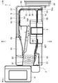
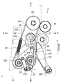
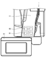
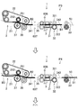
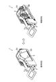
- FIG. 1 is a perspective view showing an external appearance of the bill counting apparatus as viewed from the front side.
- FIG. 2 is a plan view of the bill counting apparatus.
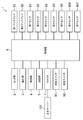
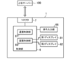
- FIG. 3 is a block diagram showing the configuration of the bill counting apparatus.
- FIG. 4 is a perspective view illustrating a modified example related to the transport unit.
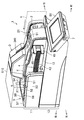
- FIG. 5 is a perspective view of the internal structure of the set unit.
- FIG. 6 is a plan view showing a partial configuration of the set unit in the set waiting state.
- FIG. 7 is a front view showing a partial configuration of the set unit in the set waiting state.
- FIG. 8 is a plan view showing a partial configuration of the set unit in the extended state.
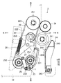
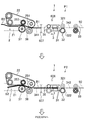
- FIG. 9 is a perspective view of various rollers of the set unit.
- FIG. 1 is a perspective view showing an external appearance of the bill counting apparatus as viewed from the front side.
- FIG. 2 is a plan view of the bill counting apparatus.
- FIG. 3 is a block diagram showing the configuration of the bill counting
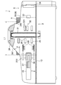
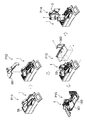
- FIG. 10 is a cross-sectional view illustrating the configuration of the identification unit.
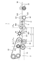
- FIG. 11 is a plan view showing configurations of the set unit and the identification unit.
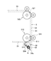
- FIG. 12 is a perspective view illustrating a modified example related to the identification unit.
- FIG. 13 is a schematic diagram illustrating the configuration of the reject unit when the switching unit is in the first position.
- FIG. 14 is a schematic diagram illustrating the configuration of the reject unit when the switching unit is in the second position.
- FIG. 15 is a plan view showing the configuration of the holding unit.
- FIG. 16 is an enlarged perspective view of the configuration of the holding unit.
- FIG. 17 is a block diagram illustrating a configuration related to screen display and operation input.
- FIG. 18 is an example of a display screen at the time of bill counting.
- FIG. 18 is an example of a display screen at the time of bill counting.
- FIG. 19 is an enlarged plan view showing a part of the upper surface of the banknote counting apparatus.
- FIG. 20 is a perspective view illustrating a roller constituting the thickness sensor of the identification unit.
- FIG. 21 is a plan view showing the configuration of the thickness sensor of the identification unit.
- FIG. 22 is a side view showing a roller constituting the thickness sensor of the identification unit.
- FIG. 23A is an explanatory diagram illustrating a part of a procedure for controlling the conveyance of banknotes from the set unit to the identification unit.
- FIG. 23B is an explanatory diagram illustrating a part of a procedure for controlling the conveyance of banknotes from the set unit to the identification unit.
- FIG. 24 is a plan view for explaining a conveyance stop position of reject banknotes.
- FIG. 25 is a plan view showing a second embodiment of the holding unit.
- FIG. 26 is a perspective view showing a bill striker and a bill guide lever of the holding portion.
- FIG. 27 is a plan view showing a rotation state of the tag slap of the holding unit.
- FIG. 28 is a perspective view showing a stopper of the holding portion.
- FIG. 29 is a side view showing the stopper of the holding portion.
- FIG. 30 is a perspective view showing a mounting structure of the stopper of the holding portion.
- FIG. 31 is a diagram illustrating a screen display example of the first display and the second display.
- FIG. 32 is a diagram for explaining a change in the display form of the display.
- FIG. 33 is a diagram for explaining a change in the display form of the display.
- FIG. 32 is a diagram for explaining a change in the display form of the display.
- FIG. 34 is a view in which the guide of the bill counting device is in a use state and a view in an open state.
- FIG. 35 is a diagram for explaining a disassembling procedure of the bill counting device.
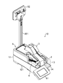
- FIG. 36 is a perspective view showing a second embodiment of the bill counting device.
- FIG. 1 shows the appearance of a bill counting device 1 (hereinafter also simply referred to as device 1).
- the device 1 performs bill identification and counting.
- the device 1 identifies at least the authenticity and denomination of the banknote.
- the device 1 can identify and count a plurality of currencies.
- the currency to be counted is set in advance.
- the currency to be counted can be changed.
- the apparatus 1 is used for identifying and counting bills handed over from customers in facilities such as a game hall, for example. For example, a customer hands a bill to a person in charge at a game hall when the bill is exchanged for a chip used for a game.
- the device 1 is a desktop type that is used by being placed on a table, counter, desk, table or the like. As will be described later, the device 1 is small and does not take up space even when placed on a table or the like.
- the right front side of FIG. 1 is referred to as the front of the apparatus 1
- the left back side of the paper is referred to as the back of the apparatus 1
- the right back side of the paper is referred to as the right of the apparatus 1
- the left front side of FIG. The person in charge usually uses the apparatus 1 with the front side of the apparatus 1 facing toward him.
- the apparatus 1 is composed of two parts, an upper part 11 and a lower part 12, overlapping in the vertical direction.
- the upper part 11 and the lower part 12 of the device 1 are separated by a partition plate 13.
- the upper part 11 of the apparatus 1 is configured to perform identification and counting while conveying bills to be counted.
- the apparatus 1 includes a set unit 2 configured to set bills to be counted, an identification unit 3 configured to identify and count banknotes, and a configuration configured to hold the identified banknotes.
- a transport unit 5 configured to transport the banknotes fed from the set unit 2 one by one through the identification unit 3 to the holding unit 4.
- an approval (ACCEPT) switch 91 and a erasure (CLEAR) switch 92 configured as mechanical switches are provided on the front side of the upper surface of the upper portion 11 (see also FIG. 19).
- the lower part 12 of the apparatus 1 is configured to accommodate various devices necessary for operating the apparatus 1. Specifically, although not shown in FIG. 1, the lower part 12 of the apparatus 1 accommodates a control unit 6 (see FIG. 3) that controls the operation of each unit 2, 3, 4, and 5.
- the lower portion 12 of the apparatus 1 also houses a motor that is a driving source for various operations performed in the respective sections 3, 4, and 5, a belt and a gear that transmit driving force, and the like.
- a connector 7 is provided at the lower part 12 of the apparatus 1.
- a power cord for supplying power to the device 1 and a cable for connecting the device 1 to the external device or connecting the external device to the device 1 are connected to the connector 7.
- the apparatus 1 also includes two displays, a first display 81 and a second display 82 (see FIG. 2) in the example disclosed herein.
- the first display 81 is a display mainly for the person in charge to see, and is arranged at the front of the apparatus 1.
- the second display 82 is a display mainly for the customer to see, and is arranged at the rear part of the device 1.
- the display contents of the first display 81 and the second display 82 can also be confirmed from, for example, a monitoring camera attached to a ceiling or the like installed in a facility such as a game hall or a monitor or the like.
- the second display 82 is not essential.
- the set unit 2 is arranged on the right side of the front part of the apparatus 1 as shown in FIGS.
- the upper surface of the partition plate 13 functions as a set surface on which the bills B are set in the setting unit 2.
- the setting unit 2 is configured to set the banknote B in a state where the long edge of the banknote B is down and standing on the upper surface of the partition plate 13.
- the set unit 2 is opened above and forward of the device 1.
- the banknote B is set in the set unit 2
- the upper part of the banknote B and the rear part in the transport direction (as will be described later, the leading side in the transport direction of the banknote B is the tip of the banknote B, and the opposite side is the back of the banknote B.
- the rear part of time jumps up and forward of the device 1, respectively.
- the person in charge and the customer can see at least a part of the bill B set in the setting unit 2.
- a base 14 for receiving the bill B that has jumped out in front of the apparatus 1 is attached to the front side of the setting unit 2.
- the upper surface of the base 14 is flush with the upper surface of the partition plate 13.
- the longitudinal edge of the bill B hits both the set surface of the set unit 2 and the upper surface of the table 14.
- the setting unit 2 is configured to be able to set a plurality of banknotes B at a time in a state where they are arranged in the horizontal direction. Banknotes B of different sizes may be mixed together.
- the set unit 2 has a bill B feeding mechanism. The feeding mechanism feeds the bills B set in the setting unit 2 one by one.
- the identification unit 3 is arranged on the right side of the central portion of the apparatus 1 in the front-rear direction.
- the identification unit 3 and the set unit 2 are adjacent to each other in the front-rear direction of the device 1.
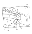
- the identification unit 3 includes an entrance 341 through which the bill B enters and an exit 342 from which the bill B exits.
- the banknotes drawn out from the set unit 2 pass through the identification unit 3.
- the identification unit 3 has a sensor that acquires information about the banknote B.
- the identification unit 3 determines whether the banknote B is an acceptable normal banknote or an unacceptable reject banknote based on information acquired by the sensor when the banknote B passes.
- the identification unit 3 also performs true / false determination of banknotes B and counts of normal banknotes.
- the holding part 4 is arranged on the left side of the front part of the device 1.
- the holding unit 4 and the set unit 2 are adjacent to each other in the left-right direction of the device 1.
- the upper surface of the partition plate 13 functions as a holding surface that holds the banknote B in the holding unit 4.
- the holding unit 4 holds the bill B in a state where the bill B is erected on the upper surface of the partition plate 13 with the longitudinal edge of the bill B facing down.
- maintenance part 4 is comprised so that the several banknote B can be hold
- the holding part 4 is opened upward, forward and leftward of the device 1. As shown by a two-dot chain line in FIG. 1, the upper part of the bill B held by the holding unit 4 jumps upward from the holding unit 4. The person in charge and the customer can see the bill B held in the holding unit 4.
- the conveyance unit 5 has a conveyance path provided from the setting unit 2 to the holding unit 4. As shown in FIG. 2, the conveyance path includes a first conveyance path 51, a second conveyance path 52, and a third conveyance path 53. The conveyance path as a whole is arranged so as to form a U shape in plan view.
- the conveyance unit 5 conveys the sheet B one by one in a state where banknotes B are erected on the upper surface of the partition plate 13.
- Each of the transport paths 51, 52, and 53 is configured by guides 55, 56, and 57 that are arranged at predetermined intervals in the horizontal direction.
- the guides 55, 56, and 57 are opposed to the front and back surfaces of the bill B that is conveyed in an upright state.
- the heights of the guides 55, 56, and 57 are lower than the height of the bill B (that is, the short length).
- An opening 50 that opens upward is provided between the guides. As shown by a two-dot chain line in FIG. 1, the upper part of the bill B being conveyed jumps upward from the opening 50. The person in charge and the customer can see the bill B being conveyed.
- a branch path 58 is connected to a connection portion between the first transport path 51 and the second transport path 52.
- a reject portion 54 is configured by a part of the second conveyance path 52 and the branch path 58.
- the reject part 54 is a part that discharges the banknote B determined as a reject banknote by the identifying part 3.
- the reject part 54 opens upward and opens on the right side surface of the rear part of the apparatus 1 to form a reject port 54a.
- a part of the reject banknote paid out to the reject unit 54 jumps out from the reject port 54 a to the right side of the apparatus 1, and an upper part of the reject banknote pops up from the reject unit 54. The person in charge and the customer can see the rejected banknote.
- FIG. 3 shows a block diagram related to the operation of the apparatus 1.
- the set unit 2, the identification unit 3, the holding unit 4, and the transport unit 5 are electrically connected to the control unit 6 so that signals can be transmitted and received.
- the first display 81 and the second display 82 are also electrically connected to the control unit 6.
- the first display 81 is configured by a touch panel type display. The person in charge can perform various operations on the first display 81.
- the second display 82 is not a touch panel display, and only displays. The first display 81 and the second display 82 display at least the count result.
- the first display 81 becomes effective when the first display 81 is connected to a predetermined port, and the second display 82 is The touch panel function may be disabled as a result of connection to the port.
- the approval switch 91 and the erasure switch 92 are also electrically connected to the control unit 6.
- the person in charge can make a predetermined input by pressing these switches 91 and 92.
- the host server 100 is connected to the control unit 6 via a connector 7 (see FIG. 17).
- the host server 100 centrally manages the game hall. Note that the apparatus 1 may be operated stand-alone without being connected to the upper server 100.
- the controller 6 is connected with a first sensor 61, a second sensor 62, a third sensor 63, a fourth sensor 64, and a fifth sensor 65.
- Each of the first to fifth sensors 61 to 65 detects the bill B and outputs a detection signal to the control unit 6.
- the first sensor 61 is disposed in the vicinity of the set unit 2.
- the first sensor 61 detects that the bill B is set in the setting unit 2.
- the second sensor 62 is disposed in the second transport path 52. When the second sensor 62 detects the passage of the bill B, the conveyance of the bill B that is suspected of being a fake bill is stopped.
- the third sensor 63 is disposed in the third conveyance path 53.
- the third sensor 63 detects that the banknote B has been paid out to the holding unit 4.
- the fourth sensor 64 is disposed in the vicinity of the reject port 54a.
- the fourth sensor 64 detects that the banknote B paid out to the reject port 54a has been extracted from the reject port 54a.
- the fifth sensor 65 is disposed in the holding unit 4.
- the fifth sensor 65 detects that the banknote B held by the holding unit 4 has been removed.
- a sixth sensor 606 and a seventh sensor 607 are connected to the controller 6.
- the sixth sensor 606 is provided in the identification unit 3 as shown in FIG.
- the sixth sensor 606 detects the leading edge of the bill B fed from the set unit 2 and sent into the identification unit 3.
- the detection result of the sixth sensor 606 is used for feeding and stopping bills in the set unit 2.
- the detection result of the sixth sensor 606 is also used for setting the detection timing of each sensor in the identification unit 3 described later.
- the seventh sensor 607 is disposed at a predetermined position between the set unit 2 and the identification unit 3 as shown in FIG. More specifically, the seventh sensor 607 is disposed between a drive roller 251 and a grip roller 35, which will be described later, as shown in FIG.
- the seventh sensor 607 detects the leading edge of the bill B. Although details will be described later, based on the detection result of the seventh sensor 607, the control unit 6 controls the feeding of the banknote B to the identification unit 3.
- the counting operation of the device 1 will be described.
- the first sensor 61 detects the banknote B.
- the control unit 6 receives the detection result of the first sensor 61 and feeds the bills B from the set unit 2 one by one.
- the bill B fed out from the set unit 2 passes through the identification unit 3.
- the identification part 3 acquires the information regarding the banknote B with a sensor, and determines whether each banknote is an acceptable normal banknote or an unacceptable reject banknote based on the information. For example, when the bill B is a currency other than the currency to be counted, it is determined to be a reject bill. Moreover, when two or more banknotes are overlapped and conveyed, it is determined that the banknote is a reject banknote.
- the identification unit 3 also identifies the denomination of normal banknotes.
- the identification unit 3 also performs authenticity determination of each banknote and counts of normal banknotes.
- the banknote B that has passed through the identification unit 3 is transported by the transport unit 5 to reach the second transport path 52 from the first transport path 51. If the bill B is a normal bill when the second sensor 62 detects the passage of the bill B, the bill B is transported to the third transport path 53 as it is.
- the bill B that has reached the third transport path 53 passes through the third sensor 63 and is then paid out to the holding unit 4.
- the holding unit 4 sequentially holds the banknotes B that have been paid out.
- the bills B are held side by side in the horizontal direction.
- the control unit 6 feeds the next banknote B from the set unit 2.
- the control unit 6 displays the count value on the first display 81 and the second display 82 in real time during the counting operation.
- the control unit 6 displays the counting result, that is, the total amount, in the first display 81 and the second display 82. To display. Thus, the counting operation of the device 1 is completed. After the counting is completed, the person in charge removes the banknote B held by the holding unit 4 by hand. The fifth sensor 65 detects that the banknote B has been removed.
- the person in charge performs a count value determination process or the like by pressing a touch button provided on the first display 81 or a switch 91 or 92 provided on the upper surface of the upper portion 11 of the apparatus 1.
- the control unit 6 moves the transport unit 5 after the bill B reaches the second transport path 52 and passes a switching unit 59 described later. Pause. Then, the control part 6 operates the conveyance part 5 so that the banknote B located in the 2nd conveyance path 52 is conveyed in reverse direction. The bill B is transported from the second transport path 52 toward the branch path 58 and is paid out to the reject unit 54. In this state, the operation of the device 1 stops. The person in charge removes the reject banknotes paid out to the reject unit 54 by hand. When the fourth sensor 64 detects that the reject banknote has been removed, the control unit 6 resumes the counting operation of the device 1.
- the control unit 6 stops the conveyance of the banknote B by stopping the conveyance unit 5. Thereafter, the control unit 6 transmits to the upper server 100 that the non-genuine bill has been detected while keeping the bill B in the transport path 52.
- the device 1 is a desktop type, but is not limited thereto, and may be accommodated in a space under the table.
- the device 1 may be placed on the side of the table after being turned sideways (specifically, rotated 90 ° around an axis extending along the front-rear direction of the device 1).
- the transport unit 5 transports the banknotes B longitudinally one by one with the banknotes B laid down.
- the opening part 50 of the apparatus 1 will open sideways, and the edge part of the banknote B in conveyance will protrude to the side from the opening part 50.
- FIG. When installed on the side of the table, it does not interfere with the games played on the table.
- the first transport path 51 includes a first guide 55 and a second guide 56.
- the second transport path 52 includes a second guide 56 and a third guide 57.
- the third conveyance path 53 includes a second guide 56 and a third guide 57.
- the first guide 55 extends in the front-rear direction on the right side of the apparatus 1 from the rear part of the apparatus 1 to the center part in the front-rear direction. As shown in FIG. 2, the first guide 55 has an I shape in plan view.
- the first guide 55 constitutes a part of the right side surface of the device 1.
- the first guide 55 extends from the upper part 11 to the lower part 12 of the device 1.
- the first guide 55 also constitutes a part of the identification unit 3 on one side across the conveyance path of the bill B.
- the second guide 56 is disposed at the center in the left-right direction of the device 1. In other words, the second guide 56 is disposed inward of the apparatus 1 with respect to the first guide 55 and the third guide 57.
- the second guide 56 extends in the front-rear direction from the rear part to the front end part of the apparatus 1.
- the second guide 56 constitutes a part of the set part 2 and a part of the holding part 4.
- the second guide 56 also constitutes a part of the identification unit 3 on one side across the conveyance path of the bill B.
- the third guide 57 is substantially L-shaped in plan view as shown in FIG.
- the third guide 57 also constitutes a part of the rear surface of the device 1 and a part of the left side surface.
- the third guide 57 is provided above the partition plate 13.
- the third guide 57 is provided only in the upper part 11 of the device 1.
- the first guide 55 and the third guide 57 are arranged so as to surround the second guide 56 arranged at the center of the apparatus 1.
- the first transport path 51, the second transport path 52, and the third transport path 53 configured by the first guide 55, the second guide 56, and the third guide 57 are U-shaped in plan view.
- An opening 50 that opens upward is provided along the U-shaped conveyance path.
- each of the first guide 55, the second guide 56, and the third guide 57 is lower than the short length of the smallest bill B among the bills B that can be counted in the apparatus 1.
- the banknote B jumps upwards from the opening part 50 opened upwards. For this reason, a person can see the bill B being conveyed from above the apparatus 1.
- this apparatus 1 has the set part 2 opened upward and forward. A person can see the bill B set in the setting unit 2 from above the device 1.
- the several banknote B set to the setting part 2 is located in the horizontal direction in the respectively standing state. All of the plurality of banknotes B set in the setting unit 2 can be viewed from above the apparatus 1.
- the holding part 4 is also opened upward, forward and leftward. A person can see the banknote B held in the holding unit 4 from above the device 1. Moreover, the several banknote B hold
- the person in charge and the customer can always see the bill B from above the device 1 while the device 1 is counting. Thereby, the apparatus 1 can ensure the high reliability of the counting result.
- maintenance are all performed in the state which stood up with the longitudinal edge down.
- the device 1 becomes compact in the horizontal direction, which is advantageous in forming a small size.
- the banknotes B are conveyed in the longitudinal direction in a standing state. Unlike this, you may comprise a banknote counter so that the banknote B may be conveyed longitudinally or short-sided. In this configuration, for example, a part of the bill B being conveyed may be caused to jump out of the opening to the side of the bill counting device.
- a cover member 510 made of a light transmissive material may be attached in the transport unit 5. Thereby, it becomes possible to always see the banknote B conveyed along each conveyance path 51,52,53 through the cover member 510.
- FIG. The cover member 510 can protect the bill B being conveyed. As a result, the banknote B can be transported smoothly.
- a part of banknote B currently conveyed along each conveyance path can be seen. You may comprise so that it can do.
- the guide is as described above. It is not necessary to make it lower than the height of the banknote B. That is, a part of the bill B being transported is transported along each transport path through the portion of the guide made of a transparent material without having to jump out from the opening provided between the guides. It becomes possible to see at least a part of the bill B.
- the L-shaped third guide 57 in plan view may be divided into a guide that configures the second transport path 52 together with the second guide 56 and a guide that configures the third transport path 53 together with the second guide 56.
- the layout of the conveyance path shown above is an example.
- the conveyance path may be arranged in a straight line, for example.
- the shape of the guide is appropriately changed according to the layout of the conveyance path.
- FIG. 5 is a perspective view of the internal structure of the set unit 2.
- FIG. 6 is a view of a part of the set unit 2 in the set waiting state as viewed from above.
- FIG. 7 is a view of a part of the set unit 2 in the set waiting state as viewed from the front.
- FIG. 8 is a view of a part of the set unit 2 in the extended state as viewed from above.
- FIG. 9 is a perspective view of various rollers of the setting unit 2.
- the set unit 2 includes an opening 21 (see FIG. 1) into which the bill B is inserted, a partition plate 13 on which the set bill B is placed, a feeding belt 22 that feeds the set bill B, and a bill B.
- the presser 24 For driving the guard 23 that prevents the bill B and the feeding belt 22 from contacting each other at the time of setting, the presser 24 that presses the bill B against the feeding belt 22 when the bill B is fed, various rollers, and the feeding belt 22.
- Motor 26 The set unit 2 enters a set waiting state when the bill B is set in the set unit 2, and enters a payout state when the set bill B is fed out. The set waiting state and the feeding state will be described later.
- the opening 21 is formed by the first guide 55 and the second guide 56 and is disposed on the right side of the front portion of the apparatus 1.
- the opening 21 is a portion formed by the edge of the first guide 55 and the edge of the second guide 56, in other words, the opening edge.
- the opening 21 opens upward and forward of the device 1.
- the upper part of the device 1 corresponds to one side in the width direction of the feeding belt 22 described later in detail. That is, the opening 21 opens on one side in the width direction of the feeding belt 22.
- the front of the apparatus 1 corresponds to the opposite side of the feeding direction of the bill B by the feeding belt 22 from the direction in which the bill B is fed out.
- the opening 21 is also open on the opposite side to the direction in which the bill B is fed out of the feeding direction of the bill B by the feeding belt 22. Therefore, the banknote B is inserted into the set part 2 from the top to the bottom or from the front to the back through the opening 21.
- the partition plate 13, the feeding belt 22, the guard part 23, the presser part 24, various rollers and the motor 26 are arranged on the inner side of the opening part 21.
- the feeding belt 22 is an annular endless belt.
- the outer peripheral surface of the feeding belt 22 is referred to as “front surface 221”, and the inner peripheral surface is referred to as “back surface 222”.
- a direction orthogonal to both the thickness direction and the longitudinal direction (circumferential direction) of the feeding belt 22 is referred to as a “width direction”.
- a plurality of teeth (not shown) extending in the width direction are arranged at equal intervals in the longitudinal direction on the front surface 221 and the back surface 222 of the feeding belt 22.
- the front teeth and the back teeth have the same shape and are arranged at the same positions.
- the same tooth as the tooth on the front surface 221 is provided on the back surface 222 of the portion of the feeding belt 22 where the tooth is provided on the front surface 221.
- the feeding belt 22 is disposed on the partition plate 13 in a state where the width direction thereof matches the normal direction of the partition plate 13.
- the various rollers include at least a driving roller 251, a driven roller 252, a gate roller 253, a kick roller 254, a guide roller 36, and a separation roller 37, as shown in FIG. .
- These rollers have a rotation shaft extending in a direction along the vertical direction, and are disposed on the same side as the feeding belt 22 with respect to the partition plate 13.
- the rotation shafts of the driving roller 251, the driven roller 252, the gate roller 253, and the kick roller 254 are arranged on the one surface side of the bill B inserted into the setting unit 2 rather than the opening 21.
- the rotation shafts of the guide roller 36 and the separation roller 37 are arranged on the right side of the apparatus 1 with respect to the opening 21 so as to be located on the other surface side of the bill B.
- Each of the driving roller 251 and the gate roller 253 is an example of a “feeding roller”. Further, the feeding belt 22, the driving roller 251, the gate roller 253, the guide roller 36, and the separation roller 37 constitute a “feeding unit” in the present embodiment.
- the feeding belt 22 is wound around the driving roller 251 and the driven roller 252.
- the gate roller 253 and the kick roller 254 are disposed inside the feeding belt 22.
- the guide roller 36 and the separation roller 37 are disposed outside the feeding belt 22.
- the driving roller 251 is configured to sandwich the bill B set in the setting unit 2 via the feeding belt 22 and feed the bill B to the identification unit 3. Specifically, the drive roller 251 is rotationally driven by the motor 26. As shown in FIG. 5, the motor 26 is disposed on the opposite side of the feeding belt 22 with the partition plate 13 interposed therebetween. A plurality of teeth that mesh with the teeth of the feeding belt 22 are provided on the outer peripheral surface of the drive roller 251. When the driving roller 251 is driven by the motor 26, the feeding belt 22 is driven. The driving roller 251 rotates counterclockwise in FIGS. 6 and 8, and the feeding belt 22 also rotates counterclockwise. This rotation direction is a direction in which the bill B set on the right side of the feeding belt 22 is fed out.
- the gate roller 253 is disposed in front of the driving roller 251 in the front-rear direction. Similarly to the driving roller 251, the gate roller 253 is configured to sandwich the banknote B set in the setting unit 2 via the feeding belt 22 and to feed out the banknote B to the identification unit 3. A plurality of teeth that mesh with the teeth of the feeding belt 22 are provided on the outer peripheral surface of the gate roller 253.
- the gate roller 253 rotates in the direction in which the banknote B is fed out when the feeding belt 22 is driven. That is, the gate roller 253 rotates counterclockwise in FIGS.
- One swinging end of a swinging plate portion 27 constituting a bell crank is connected to the rotation shaft of the gate roller 253 by being pivotally supported at the center thereof.
- An urging member 28 that urges the oscillating plate 27 in the clockwise direction in FIG. 6 is connected to the other oscillating end of the oscillating plate 27.
- the biasing member 28 is composed of, for example, a tension spring, and the magnitude of pressure (gate pressure) when the gate roller 253 presses the bill B via the feeding belt 22 through adjustment of the spring constant, As a result, it is possible to adjust the magnitude of the gripping force in the set portion 2.
- the kick roller 254 is disposed in front of the gate roller 253 in the front-rear direction. Therefore, the drive roller 251, the gate roller 253, and the kick roller 254 are arranged along a direction substantially parallel to the bill B feeding direction.
- the kick roller 254 is configured to pay out banknotes via the feeding belt 22, and kicks the banknotes B in the feeding direction when the banknotes B are inserted into the set unit 2.
- the driven roller 252 is disposed at substantially the same position as the kick roller 254 in the front-rear direction, and is disposed to the left of the kick roller 254 in the left-right direction (that is, a position away from the opening 21). Therefore, the driving roller 251, the gate roller 253, the kick roller 254, and the driven roller 252 are not arranged in a straight line in a plan view, but the kick roller 254 is a corner as shown in FIGS. They are arranged in an inverted L shape. Similar to the drive roller 251, a plurality of teeth that mesh with the teeth of the feeding belt 22 are provided on the outer peripheral surface of the driven roller 252.
- the guide roller 36 is driven to rotate in the direction in which the bill B is fed out. That is, the guide roller 36 rotates clockwise in FIGS. By rotating in this way, it operates to pull out one of the plurality of banknotes B.
- the separation roller 37 is located upstream of the guide roller 36 in the feeding direction.
- the separation roller 37 and the driving roller 251 are drivingly connected via a gear.
- the separation roller 37 is rotationally driven in a direction opposite to the bill B feeding direction. That is, the separation roller 37 rotates counterclockwise in FIGS.
- the set unit 2 sandwiches the feeding belt 22 between the driving roller 251 and the guide roller 36 and also sandwiches the feeding belt 22 between the gate roller 253 and the separation roller 37 when the bill B is not present.
- the setting unit 2 kicks out the bill B in the feeding direction by the kick roller 254 and sandwiches the bill B between the gate roller 253 and the separation roller 37.
- the gate roller 253 sandwiches the bill B through the feeding belt 22 by pressing the feeding belt 22 with a predetermined gate pressure.
- the sandwiched bill B is sent out in the feeding direction by the rotation of the gate roller 253. Even when a plurality of banknotes B are about to be fed out by the feeding belt 22, the feeding of the banknotes B other than the banknotes B in contact with the feeding belt 22 is prevented by the rotation of the separation roller 37 in the opposite direction.
- the set unit 2 sandwiches the bill B sent out by the gate roller 253 between the driving roller 251 and the guide roller 36 and sends out the bill B in the feeding direction by the rotation of the driving roller 251 and the guide roller 36.
- the driving roller 251 sandwiches the bill B via the feeding belt 22, similarly to the gate roller 253.
- the banknote B is drawn out in a standing state and taken into the identification unit 3.
- the drive side folding roller 251a is each provided in the upper end and lower end of the drive roller 251 (a lower end side is abbreviate
- a guide-side folding roller 36a is provided at a position corresponding to the driving-side folding roller 251a at the upper end and the lower end of the guide roller 36, respectively.
- the driving roller 251, the gate roller 253, the kick roller 254, and the driven roller 252 have an inverted L shape with the kick roller 254 as a corner in plan view. Are lined up.
- This configuration is more compact in the feeding direction of the bills B than the configuration in which various rollers are arranged in a straight line in the front-rear direction of the apparatus 1.
- the parts (various rollers, feeding belt 22 and urging member 28, etc.) constituting the set unit 2 are gathered in the feeding direction of the bills B, it is advantageous for making the set unit 2 modular.
- the motor 26 is arrange
- the set unit 2 can be made compact and modular, and as a result, the apparatus 1 can be made compact.
- a portion of the feeding belt 22 upstream of the kick roller 254 extends in a direction away from the opening 21 (specifically, the left direction of the device 1).
- the guard part 23 includes a first guard part 231, a second guard part 232, and a locking part 233 as shown in FIG.
- the guard part 23 is supported so as to be swingable around the rotation axis X with respect to the partition plate 13, and a guard state (see FIGS. 6 and 7) that prevents contact between the bill B and the feeding belt 22, and the bill B is configured to be rotatable so as to be switched between a retracted state (see FIG. 8) that enables contact between B and the feeding belt 22.
- the retracted state is a state in which the guard portion 23 is rotated a predetermined angle in the counterclockwise direction from the guard state.
- the first guard portion 231 faces the first side surface 223 closer to the opening 21 (that is, farther from the partition plate 13) among the side surfaces of the feeding belt 22 in the guard state.
- the first guard portion 231 protrudes from the surface 221 of the feeding belt 22 in the thickness direction of the feeding belt 22.
- the second guard part 232 is disposed below the first guard part 231. As shown in FIG. 7, the second guard portion 232 faces the second side surface 224 farther from the opening 21 (that is, closer to the partition plate 13) among the side surfaces of the feeding belt 22 in the guard state.
- the second guard portion 232 protrudes from the surface of the feeding belt 22 in the thickness direction of the feeding belt 22.
- the first guard portion 231 has a first inclined surface 234 that is inclined so as to move away from the surface 221 in the thickness direction of the feeding belt 22 as it approaches the first side surface 223 in the width direction of the feeding belt 22.
- the second guard portion 232 has a second inclined surface 235 that is inclined so as to be separated from the surface 221 in the thickness direction of the feeding belt 22 as it is separated from the second side surface 224 in the width direction of the feeding belt 22.
- the first inclined surface 234 and the second inclined surface 235 are inclined so as to be separated from the surface 221 in the thickness direction of the feeding belt 22 as the depth of the setting portion 2 increases in the width direction of the feeding belt 22.
- the locking portion 233 protrudes from the upper surface of the first guard portion 231.
- the locking portion 233 is disposed on the opposite side of the first inclined surface 234 across the rotation axis X in the first guard portion 231.
- the urging member 29 is locked to the locking portion 233.
- the urging member 29 urges the guard portion 23 in the clockwise direction in FIG.
- the guard part 23 is urged by the urging member 29 so as to be maintained in the guard state.
- the first guard portion 231 and the second guard portion 232 protrude from the surface 221 of the feeding belt 22 in the thickness direction of the feeding belt 22.
- the first guard part 231 and the second guard part 232 are more than the surface 221 in the thickness direction of the feeding belt 22. Retracted to the retracted position. That is, when viewed in the vertical direction, the first side surface 223 of the feeding belt 22 is hidden by the first guard portion 231 in the guard state, whereas the first side surface 223 is exposed in the retracted state. .
- the pressing portion 24 has a main body portion 240, a first contact portion 241, a second contact portion 242, and a drive shaft 243.
- the main body 240 has a generally plate shape.
- the main body 240 is disposed at a position facing the feeding belt 22.
- the first contact part 241 and the second contact part 242 are provided so as to protrude from the main body part 240 on the surface of the main body part 240 facing the feeding belt 22.
- the first contact portion 241 and the second contact portion 242 are arranged in the vertical direction. In the thickness direction of the feeding belt 22, the first contact portion 241 and the first guard portion 231 face each other, and the second contact portion 242 and the second guard portion 232 face each other.
- the first contact portion 241 has a third inclined surface 244 that is inclined so as to move away from the main body portion 240 in the thickness direction of the feeding belt 22 as it goes to the back of the set portion 2 in the width direction of the feeding belt 22.
- the second contact portion 242 has a fourth inclined surface 245 that is inclined so as to be away from the main body portion 240 in the thickness direction of the feeding belt 22 as it goes deeper into the set portion 2 in the width direction of the feeding belt 22. ing.
- the main body 240 is connected to the drive shaft 243.
- the drive shaft 243 extends in a direction perpendicular to the partition plate 13 and is rotatably supported by the partition plate 13.
- the drive shaft 243 is rotationally driven by a motor (not shown) disposed on the back side of the partition plate 13.
- the presser 24 is in a retracted state (see FIG. 6) in which the main body 240 is substantially parallel to the bill B feeding direction, and the main body 240 is counterclockwise in FIG.
- the state is switched between the presser state rotated by a predetermined angle (see FIG. 8).
- the guard part 23 When the presser part 24 is in the retracted state, the guard part 23 is in the guard state, and when the presser part 24 is in the presser state, the guard part 23 is in the retracted state.
- the presser unit 24 When the set unit 2 is in the set waiting state, the presser unit 24 is in the retracted state, while when the set unit 2 is in the extended state, the presser unit 24 is in the presser state.
- the presser part 24 When the presser part 24 is in the retracted state, the first contact part 241 and the second contact part 242 are located at positions sufficiently away from the feeding belt 22. In the thickness direction of the feeding belt 22, there is a sufficient space between the first contact portion 241 and the first guard portion 231 and between the second contact portion 242 and the second guard portion 232. It is secured. In this state, the presser portion 24 allows the guard portion 23 to rotate (specifically, the clockwise rotation in FIG. 6), and the guard portion 23 is in the guard state according to the biasing by the biasing member 28. become.
- the first contact portion 241 and the second contact portion 242 contact the bill B and press the bill B against the surface 221 of the feeding belt 22.
- the guard portion 23 is in the retracted state in conjunction with it.
- the presser portion 24 is in the presser state, in the thickness direction of the feeding belt 22, between the first contact portion 241 and the first guard portion 231, and between the second contact portion 242 and the second guard portion.
- the distance between the H.232 and the H.232 is narrower than that in the retracted state.
- the presser part 24 restricts the rotation of the guard part 23, and the guard part 23 is held in the retracted state.
- the operation of the setting unit 2 will be described.
- the set unit 2 is in the set waiting state, that is, when waiting to set the bill B
- the guard unit 23 is in the guard state
- the presser unit 24 is in the retracted state. Therefore, when the set unit 2 is viewed from above through the opening 21, the first side surface 223 of the feeding belt 22 is covered with the first guard unit 231 and is not exposed. Therefore, even when the bill B is inserted from above through the opening 21, that is, in the width direction of the feeding belt 22, the bill B is not caught on the first side surface 223 of the feeding belt 22. Can be smoothly inserted into the set portion 2.
- the presser portion 24 is disposed at a position having a sufficient interval between the presser portion 24 and the guard portion 23. Therefore, the banknote B can be smoothly inserted into the set unit 2 without contacting the guard unit 23 or the presser unit 24.
- the 1st guard part 231 has the 1st inclined surface 234.
- FIG. The first inclined surface 234 is inclined so as to move away from the surface 221 in the thickness direction of the feeding belt 22 as it goes deeper into the set portion 2 in the width direction of the feeding belt 22. Therefore, even if the bill B comes into contact with the first guard portion 231, the bill B is guided by the first inclined surface 234 so as to move away from the surface 221 of the feeding belt 22 as it goes deeper into the set portion 2. In this way, the bill B is smoothly guided to the back of the setting unit 2.
- a second guard portion 232 is provided at a position facing the second side surface 224 of the feeding belt 22, and the second guard portion 232 protrudes from the surface 221 in the thickness direction of the feeding belt 22. For this reason, the second guard portion 232 prevents the bill B from contacting the feeding belt 22 even at the back of the set portion 2.
- the second guard portion 232 has a second inclined surface 235 that is inclined so as to move away from the surface 221 in the thickness direction of the feeding belt 22 as it goes to the back of the set portion 2 in the width direction of the feeding belt 22. . Therefore, even if the bill B comes into contact with the second guard portion 232, the bill B is guided by the second inclined surface 235 so as to move away from the surface 221 of the feeding belt 22 as it goes deeper into the set portion 2. In this way, the bill B is smoothly guided to the back of the setting unit 2.
- the bill B may come into contact with the presser portion 24.
- the first contact part 241 and the second contact part 242 protrude from the main body part 240, so that the bill B contacts the first contact part 241 or the second contact part 242.
- the first abutting portion 241 has a third inclined surface 244 that is inclined so as to move away from the main body portion 240 in the thickness direction of the feeding belt 22 as it goes to the back of the set portion 2 in the width direction of the feeding belt 22. ing. Therefore, even if the bill B comes into contact with the first contact portion 241, the bill B is guided by the third inclined surface 244 so as to move away from the main body portion 240 as it goes deeper into the set portion 2.
- the second contact portion 242 has a fourth inclined surface 245 that is inclined so as to move away from the main body portion 240 in the thickness direction of the feeding belt 22 as it goes to the back of the set portion 2 in the width direction of the feeding belt 22. ing. Therefore, even if the bill B comes into contact with the second contact portion 242, the bill B is guided by the fourth inclined surface 245 so as to move away from the main body portion 240 as it goes deeper into the set portion 2. In this way, the bill B is smoothly guided to the back of the setting unit 2.
- the guard unit 23 is in the retracted state, and the presser unit 24 is in the presser state.
- the guard part 23 is in the retracted state, the surface 221 of the feeding belt 22 can be brought into contact with the banknote B, and the banknote B is placed on the surface 221 of the feeding belt 22 by the pressing part 24 being in the pressing state. Pressed. In this way, when the bill B comes into contact with the surface 221 of the feeding belt 22, the bill B is properly fed out by the feeding belt 22.
- the bill B fed by the feeding belt 22 passes through the separation roller 37, so that only one bill B is conveyed to the guide roller 36, and is taken into the identification unit 3 by the guide roller 36. It will be.
- the first guard portion 231 is provided.
- the bill B can be prevented from being caught on the side surface of the feeding belt 22. Thereby, the banknote B can be smoothly inserted into the set part 2.
- the second guard part 232 it is possible to prevent the bill B from coming into contact with the feeding belt 22 even at the back of the set part 2. Furthermore, even if the banknote B contacts the 2nd guard part 232 by providing the 2nd inclined surface 235 in the 2nd guard part 232, the banknote B can be smoothly guided to the back of the setting part 2 further. it can.
- the 1st contact part 241 has a 3rd inclined surface. Even if banknote B contacts the 1st contact part 241 or the 2nd contact part 242, by providing 244 and providing the 4th inclined surface 245 in the 2nd contact part 242, banknote B of set part 2 You can guide smoothly to the back.
- the apparatus 1 even when the bill B is inserted into the setting unit 2 through the opening 21 in the width direction of the feeding belt 22, the bill B can be smoothly inserted. Thereby, the banknote B can be inserted into the set unit 2 from a direction different from the feeding direction.
- the banknote B can be inserted into the set unit 2 from the feeding direction. it can. Even in this case, the first guard portion 231 and the second guard portion 232 in the guard state are in a state of protruding from the surface 221 of the feeding belt 22, so that the bill B is not brought into contact with the surface 221. 2 can be inserted.
- the guard part 23 can be switched from the retracted state to the guard state without providing a driving means such as a motor. Therefore, the set part 2 can be configured inexpensively and compactly. Will be advantageous.
- the set part 2 has the guard part 23, you may abbreviate
- FIG. although the guard part 23 has the 1st guard part 231 and the 2nd guard part 232, you may abbreviate
- the first guard portion 231 and the second guard portion 232 are provided with a first inclined surface 234 and a second inclined surface 235, respectively. At least one of the first inclined surface 234 and the second inclined surface 235 is provided. It may be omitted.
- the set unit 2 includes the presser part 24, but the first contact part 241 and the second contact part 242 of the presser part 24 are omitted, and the bill B is pressed against the feeding belt 22 by the main body part 240. You may do it. Further, any one of the first contact portion 241 and the second contact portion 242 may be omitted. Further, the first contact portion 241 and the second contact portion 242 are provided with a third inclined surface 244 and a fourth inclined surface 245, respectively. At least the third inclined surface 244 and the fourth inclined surface 245 are provided. One may be omitted.
- the opening 21 opens upward and forward, but may be configured to open only upward. In that case, the opening 21 is formed larger than the bill B to be inserted.
- the guide roller 36 may be omitted if the banknote B can be smoothly fed into the identification unit 3 by the grip roller 35, the separation roller 37, and the gate roller 253.
- FIG. 10 shows a portion of the identification unit 3 formed on the second guide 56.
- FIG. 11 shows the configuration of the set unit 2 and the identification unit 3 and the positional relationship between the set unit 2 and the identification unit 3 in plan view.
- the identification unit 3 includes an optical sensor 31 that acquires images of the front and back surfaces of the bill B, a thickness sensor 32 that detects the thickness of the bill B, and a magnetic sensor 33 that detects the magnetic characteristics of the bill B.
- the bill B Based on the image of the bill B acquired by the optical sensor 31 and the magnetic properties of the bill B acquired by the magnetic sensor 33, it is determined whether the bill B is a currency to be counted, whether it is a genuine note or a fake note , Whether it is a genuine note or a non-defective note, and the denomination of the bill B are determined. Moreover, based on the information of the thickness of the banknote B detected by the thickness sensor 32, it is determined whether the banknote B is one sheet or two or more sheets are overlapped and conveyed.
- the optical sensor 31 is disposed on each of the front side and the back side of the banknote B that is transported in the longitudinal direction with the longitudinal edge thereof standing downward.
- the optical sensor 31 is disposed so as to extend over the entire short length of the bill B.
- the upper end of the optical sensor 31 is a position higher than the upper end of the largest bill B among the bills B that can be counted in the apparatus 1 shown by a two-dot chain line in FIG.
- the thickness sensor 32 is disposed on the leading side in the transport direction (that is, the direction from the left to the right shown in FIGS. 10 and 11) with respect to the optical sensor 31.
- the thickness sensor 32 is disposed on the front side and the back side of the banknote B that is longitudinally conveyed in an upright state, and includes a driven roller 321 and a driving roller 322 that sandwich the banknote B in the thickness direction (FIG. 11). reference).
- the thickness sensor 32 and the optical sensor 31 are arranged at a distance that does not affect the operation.
- the thickness sensor 32 is also disposed at a predetermined height position from the partition plate 13.
- the thickness sensor 32 is disposed at a height corresponding to the portion of the bill B covered by the guide 55.
- the height of the thickness sensor 32 corresponds to approximately the center in the lateral direction of the largest bill B (see the two-dot chain line in FIG. 10) among the bills B that can be counted in the apparatus 1.
- the bill B is transported in a state where the long edge of the bill B hits the upper surface of the partition plate 13. For this reason, the thickness sensor 32 disposed at the height position always holds the bill B passing through the identification unit 3.
- the magnetic sensor 33 is disposed on the advance side in the transport direction with respect to the thickness sensor 32. Therefore, the optical sensor 31, the thickness sensor 32, and the magnetic sensor 33 are arranged in this order from the front of the apparatus 1 to the rear. The magnetic sensor 33 and the thickness sensor 32 are arranged at a distance that does not affect the operation.
- the magnetic sensor 33 is also disposed at a predetermined height position from the partition plate 13.
- the magnetic sensor 33 is disposed at a height corresponding to the portion of the bill B covered by the guide 55.
- the height of the magnetic sensor 33 corresponds to approximately the center in the short direction of the smallest bill B among the bills B that can be counted in the apparatus 1.
- a sixth sensor 606 is disposed on the delay side of the transport direction with respect to the optical sensor 31 (that is, on the left side in FIG. 11).
- the sixth sensor 606 detects the tip of the bill B sent into the identification unit 3. Based on the timing at which the sixth sensor 606 detects the leading edge of the bill B, the optical sensor 31, the thickness sensor 32, and the magnetic sensor 33 each set the detection timing.
- the optical sensor 31 is disposed so as to extend over the entire short length of the banknote B, it is possible to acquire images of the entire front surface and back surface of the banknote B. Since the amount of information used for identification increases, the accuracy of identification is improved. Moreover, identification can be performed quickly based on a large amount of information, and the time required for identification is shortened.
- the thickness sensor 32 and the magnetic sensor 33 are disposed below the opening 50 of the conveyance path.
- the thickness sensor 32 and the magnetic sensor 33 cannot acquire information on the portion of the banknote B that has popped out from the opening 50.
- an accurate determination can be made if the thickness is detected in a part of the banknote B. Is possible.
- the device 1 can perform counting while watching a bill B to be counted. Even if the amount of information that can be acquired by the magnetic sensor 33 decreases, the accuracy and reliability of the identification of the device 1 does not decrease.
- the identification unit 3 includes a cover unit 34 that covers the optical sensor 31.
- the cover part 34 protrudes above the first guide 55 and the second guide 56.
- the cover part 34 extends in the front-rear direction of the apparatus 1 (the left-right direction in FIG. 10). This prevents light from entering the location where the optical sensor 31 is disposed.
- an inlet portion 341 into which the bill B enters is formed on the front side of the cover portion 34.
- the exit part 342 from which the banknote B withdraws is formed in the rear side of the cover part 34.
- the identification part 3 becomes a tunnel shape.
- the inlet portion 341 continues to the set portion 2.
- the outlet 342 is continuous with the opening 50 of the transport unit 5. The distance from the upper surface of the partition plate 13 to the upper ends of the inlet portion 341 and the outlet portion 342 is longer than the short length of the largest bill B among the bills B that can be counted in the apparatus 1.
- the optical sensor 31, the thickness sensor 32, and the magnetic sensor 33 are all located within the range from the upper surface of the partition plate 13 to the upper ends of the inlet portion 341 and the outlet portion 342.
- the optical sensor 31, the thickness sensor 32, and the magnetic sensor 33 are all located on the side of the bill B that is conveyed in an upright state.
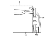
- the entrance 341 is inclined so as to have an upward gradient with respect to the bill B conveyance direction.
- the root of the inclined portion of the inlet portion 341 is located at the upper end portion of the set portion 2.
- the inclination angle ⁇ of the inlet 341 is 45 ° or less.
- the exit part 342 is hardly inclined with respect to the conveyance direction of the banknote B, the exit part 342 does not need to be inclined with respect to the conveyance direction of the banknote B. That is, the inclination angle of the outlet portion 342 may be 0 °.
- a grip roller 35 is disposed on the front side of the device 1 with respect to the optical sensor 31.
- the grip roller 35 is disposed at a distance that does not affect the operation of the optical sensor 31. While sandwiching the bill B fed out from the set unit 2, the bill B is configured to be pulled into the identification unit 3.
- the grip roller 35 is comprised by the roller which is arrange
- the grip roller 35 is an example of a “drawing roller”.
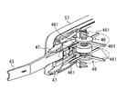
- a bill hitting roller 38 is disposed on the front side of the apparatus 1 with respect to the grip roller 35.
- the beating roller 38 is arranged at a distance that does not affect the operation of the grip roller 35.
- the bill hitting roller 38 is disposed between the set unit 2 and the grip roller 35 described above.
- the bill hitting roller 38 is configured to hit the paper surface of the bill B that is fed from the setting unit 2 and being conveyed to the identification unit 3.
- the bill hitting roller 38 is disposed on one side of the banknote B that is conveyed longitudinally in the standing state (in this example, the left side of the apparatus 1).
- the bill hitting roller 38 is composed of two rollers arranged vertically.
- Each of the two rollers is formed in an impeller shape in a plan view, and is arranged so that the front surface or the back surface of the banknote B fed out from the set unit 2 can be hit.
- the bill hitting roller 38 is driven to rotate counterclockwise in FIG. Even if the bill hitting roller 38 is bent in the bill B fed out from the setting unit 2, the bill hitting roller 38 can stably feed the bill into the identification unit 3 while correcting the deflection.
- the above-described guide roller 36 is disposed on the front side of the apparatus 1 with respect to the bill hitting roller 38.
- the guide roller 36 is disposed at a distance that does not affect the operations of the grip roller 35 and the beating roller 38.
- the guide roller 36 is disposed at a position in the transport direction corresponding to the inclined portion of the inlet portion 341.
- a force is applied to the location where the guide roller 36 is disposed, the strength of the location can be ensured by arranging the guide roller 36 at a position corresponding to the inclined location of the inlet portion 341.
- the above-described feeding belt 22 and the driving roller 251 are arranged in this order on the back side of the guide roller 36.
- the guide roller 36 is a roller for guiding the bill B from the setting unit 2 to the identification unit 3.
- the bill B guided to the identification unit 3 by the guide roller 36 reliably passes through the identification unit 3 by the grip roller 35.
- the guide roller 36 may be omitted.
- the above-described separation roller 37 is disposed on the front side of the apparatus 1 with respect to the guide roller 36.
- the separation roller 37 rotates in the direction opposite to the feeding direction of the bills B in order to feed the bills B from the setting unit 2 one by one.
- the separation roller 37 and the guide roller 36 are disposed at a distance that does not affect the operation of each other. Further, in FIG. 10, the feeding belt 22 and the gate roller (see FIG. 11) 253 are arranged in this order on the back side of the separation roller 37.
- the identification unit 3 has an entrance 341 and an exit 342, and is configured in a tunnel shape through which the bill B passes. As shown in FIG. 10, when the bill B passes through the identification unit 3, a portion of the bill B in the transport direction front side exits from the outlet portion 342, and a portion of the bill B in the transport direction rear side is the entrance portion. This is the state before entering 341 (see the shaded portion in FIG. 10).
- the cover 34 of the identification unit 3 is configured so that the length in the front-rear direction does not become too long.
- the distance L1 from the root of the inlet portion 341 to the root of the outlet portion 342 is shorter than the longitudinal length of the smallest bill B among the bills B that can be counted in the apparatus 1.
- the device 1 can perform counting while a person always looks at the banknote B. This device 1 can ensure high reliability of the counting result.
- the optical sensor 31 of the identification unit 3 is made longer than the short length of the bill B, and the identification unit 3 is formed in a tunnel shape.
- the length of the optical sensor 31 may be shortened until it becomes equal to or less than the height of the first guide 55 and the second guide 56.
- the cover part 34 of the identification part 3 can be omitted.
- the identification unit 3 does not have to be in a tunnel shape.
- the optical sensor 31 acquires an image of a part of the bill B. Even in this case, the bill B can be identified.
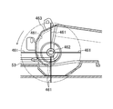
- the thickness sensor 32 is configured by a roller that is disposed on the front surface side and the back surface side of the banknote B that is conveyed in an upright state, and sandwiches the banknote B in the thickness direction.
- the thickness sensor 32 includes two driven rollers 321 arranged in the vertical direction and two drive rollers 322 arranged in the vertical direction. Have.
- the two driven rollers 321 are disposed on one side of the banknote B, and the two drive rollers 322 are disposed on the other side of the banknote B.
- the two driven rollers 321 are supported by the same rotating shaft 323 extending in the vertical direction. As the rotation shaft 323 rotates, both the two driven rollers 321 rotate.
- the two driving rollers 322 are also supported by the same rotating shaft 324 extending in the vertical direction.
- the rotation shaft 323 of the driven roller 321 is supported by the displacement detection unit 325.
- the displacement detection unit 325 supports the rotation shaft 324 so as to press the two driven rollers 321 against the driving roller 322.
- the displacement detection unit 325 also supports the rotating shaft 323 so as to allow the two driven rollers 321 to be displaced in a direction away from the driving roller 322.
- the displacement detector 325 is configured to detect the amount of displacement of the driven roller 321.
- the detection of the displacement amount may be constituted by, for example, a magnet that moves in accordance with the displacement of the driven roller 321 and a Hall element that detects the displacement of the magnet.
- the thickness sensor 32 detects the thickness of the bill B by detecting the displacement amount of the driven roller 321. For this reason, if dust or dust adheres to the surface of the driven roller 321, the driven roller 321 is displaced by the dust or dust, and the thickness of the bill B may be erroneously detected. Therefore, the thickness sensor 32 has a removal unit 326 that removes dust and dust attached to the surface of the driven roller 321.
- the removing unit 326 is disposed on the leading side in the conveyance direction of the bill B (that is, the upper side of the paper surface in FIG. 21) with the rotation shaft 323 of the driven roller 321 interposed therebetween.
- the removing unit 326 is configured by a leaf spring having a tip that contacts the surface of the driven roller 321.
- a base end portion of the removal unit 326 is fixed to the displacement detection unit 325.
- the tip of the removal unit 326 is pressed against the surface of the driven roller 321. Dust and dust adhering to the surface of the driven roller 321 are scraped off to the tip of the removing unit 326 as the driven roller 321 rotates. In this way, erroneous detection of the thickness sensor 32 due to dust and dust adhering to the surface of the driven roller 321 is prevented.
- the dust and dust scraped off by the removing unit 326 are accumulated at the tip of the removing unit 326 as virtually shown in FIG. Accumulated dust and dust fall due to their own weight.
- a space 327 in which dust and dust can be stored is provided below the driven roller 321. Since the bill counting apparatus 1 conveys the bill B in a standing state, the rotation shaft 323 of the driven roller 321 of the thickness sensor 32 extends in the vertical direction. Therefore, it is possible to drop the accumulated dust and dust as it is. In this way, dust and dust removed from the surface of the driven roller 321 can be stored in the predetermined space 327, so that it is possible to prevent the identification unit 3 from being hindered by the collected dust and dust. It becomes possible to prevent.
- dust and dust collected in the space 327 can be removed by disassembling the bill counting device 1 during maintenance of the bill counting device 1.
- the feeding rollers 251 and 253 provided in the setting unit 2 are configured to sandwich the bill B set in the setting unit 2 and feed the bill B to the identification unit 3.
- the driving roller 251 as the feeding rollers 251 and 253 sandwiches the bill B together with the guide roller 36 via the feeding belt 22.
- the gate roller 253 as the feeding rollers 251 and 253 sandwiches the bill B together with the separation roller 37 via the feeding belt 22.
- the set part 2 pays out the bill B so as to move at a predetermined payout speed V1.
- the feeding speed V1 is set via the rotational speed of the driving roller 251.
- the feeding speed V1 is set to about 1900 mm / sec.
- the set unit 2 is configured to sandwich the bill B with a predetermined grip force F1.
- the grip force F ⁇ b> 1 is set based on the configuration of various rollers and the feeding belt 22, for example, the size, number and material of various rollers, the magnitude of the gate pressure, the dynamic friction coefficient of the feeding belt 22, and the like.
- the identification unit 3 is provided with a grip roller 35 configured to sandwich the bill B fed from the set unit 2 and to draw the bill B into the identification unit 3.
- the grip roller 35 sandwiches the banknote B from both front and back sides.
- the identification unit 3 is configured to draw the banknote B so as to move at a predetermined drawing speed V2.
- the drive source that feeds out the banknote B in the set unit 2 and the drive source that transports the banknote B in the discriminating unit 3 and later are independent of each other.
- the pull-in speed V2 is set via the rotation speed of the grip roller 35.
- the pull-in speed V2 is set to about 1600 mm / sec in this example.
- the identification unit 3 is configured to sandwich the bill B with a predetermined grip force F2.
- the grip force F2 is set based on the configuration of the grip roller 35, for example, the size, number, and material of the grip roller 35.
- distance L2 (refer to Drawing 11) from drive roller 251 located in the back of a conveyance direction to grip roller 35 among feeding rollers 251 and 253 is a bill B which can be counted in apparatus 1. It is comprised so that it may become shorter than the length of the conveyance direction of the banknote B with the smallest size among them.
- the distance L2 from the driving roller 251 to the grip roller 35 is defined as the length in the front-rear direction from the position of the driving roller 251 to the position of the grip roller 35.
- the position of the driving roller 251 is defined as a position where the driving roller 251 and the guide roller 36 are in contact via the feeding belt 22.
- the position of the grip roller 35 is defined as a position where the roller constituting the grip roller 35 sandwiches the banknote B from both the front and back sides.
- the apparatus 1 can be formed smaller in the front-rear direction by the shortened distance.
- the feeding speed V1 on the set section 2 side is set to be faster than the pulling speed V2 on the identification section 3 side (V1> V2).
- the grip force F1 on the set portion 2 side is set to be smaller than the grip force F2 on the identification portion 3 side (grip roller 35 side) (F1 ⁇ F2). ).
- the beating roller 38 is disposed between the set unit 2 and the grip roller 35, the speed and grip force are different on the set unit 2 side and the identification unit 3 side. Even if the bill B that has been fed is deflected, the bill hitting roller 38 strikes the paper surface of the bill B, and as described above, the deflection of the bill B is corrected and stably fed into the identification unit 3. be able to. As a result, it is possible to prevent buckling of the bills B conveyed in an upright state, and consequently jamming of the bills B.
- the guide roller 36 can be omitted.
- the distance L3 (FIG. 11) from the gate roller 253 to the grip roller 35 is shorter than the length in the longitudinal direction of the smallest bill B among the bills B that can be counted in the apparatus 1. What is necessary is just to comprise.
- the distance L3 from the gate roller 253 to the grip roller 35 is defined as the length in the front-rear direction from the position of the gate roller 253 to the position of the grip roller 35.
- the position of the gate roller 253 is defined as a position where the gate roller 253 and the separation roller 37 are in contact via the feeding belt 22.
- the bills B fed out from the set unit 2 are sequentially fed out at a predetermined interval. As described above, the bill counting apparatus 1 shortens the distance between the set unit 2 and the identification unit 3. This causes the following inconvenience.
- the sixth sensor 606 provided in the identification unit 3 detects the leading end of the (previous) bill B.
- the setting unit 2 temporarily stops feeding the next banknote B.
- the set unit 2 resumes feeding the next bill B.
- the leading end position of the next banknote B when the set unit 2 stops feeding the next banknote B depends on the length of the previous banknote B in the longitudinal direction. That is, when the length of the previous banknote B is short, the leading end position of the next banknote B is on the front side in the transport direction (that is, the side closer to the identification unit 3) than when it is long.
- the distance between the leading edge position of the next bill B and the identification unit 3 when the feeding of the next bill B is resumed is not constant. If the distance from the tip position of the next banknote B to the identification unit 3 when restarting the next banknote B is resumed, the acceleration time of the banknote B is shortened, and the transport speed of the banknote B is a predetermined speed. The banknote B enters the identification unit 3 before reaching. In this case, since the speed of the banknote B passing through the identification unit 3 is not constant at a predetermined speed, the identification accuracy may be reduced.
- the bill counting apparatus 1 controls the conveyance between the set unit 2 and the identifying unit 3 so that the speed of the bill B passing through the identifying unit 3 is constant at a predetermined speed. Specifically, the conveyance of the banknote B is controlled using a seventh sensor 607 disposed between the set unit 2 and the identification unit 3.
- P1 in FIG. 23A shows a process in which the setting unit 2 starts to feed out the previous bill B1.
- Subsequent P2 indicates a process in which the tip of the previous bill B1 has passed through the seventh sensor 607 and the sixth sensor 606.
- the next banknote B2 of the set unit 2 is started to be fed out.
- the feeding speed of the next banknote B2 is V1 as described above. Since the previous bill B1 is pinched by the grip roller 35 of the identification unit 3, it is pulled in at a pull-in speed V2 ( ⁇ V1).
- FIG. P3 in FIG. 23B illustrates the time point when the feeding of the bill B2 of the set unit 2 is stopped. In the illustrated example, before the leading edge of the next banknote B2 reaches the seventh sensor 607, the feeding of the banknote B2 of the set unit 2 is stopped.
- the identification unit 3 passes at a predetermined speed.
- the setting part 2 pays out the banknote B2 so that the front-end
- the tip position of the next banknote B2 is set to the position of the seventh sensor 607.
- the feeding speed at this time is lower than the normal feeding speed.
- the next banknote B2 can be accurately positioned at the position of the seventh sensor 607.
- the set unit 2 resumes the feeding of the banknote B and causes the next banknote B2 to enter the identification unit 3.
- feeding of the next bill B3 is also started (see P4 in FIG. 23B and P1 in FIG. 23A).
- the tip of the next bill B2 is positioned at the position of the seventh sensor 607 after the tip passes through the sixth sensor 606 and is conveyed by a predetermined distance. May reach.
- the tip of the next bill B2 may reach the position of the seventh sensor 607.
- the setting unit 2 stops the feeding of the banknote when the seventh sensor 607 detects the leading edge of the next banknote B2. At this time, the process shifts from P2 in FIG. 23A to P4 without passing through P3 in FIG. 23B.
- the apparatus 1 is provided with the reject unit 54 that holds the discharged reject banknote.
- the reject unit 54 includes a branch path 58 and a part of the conveyance path that communicates with the branch path 58.
- the reject unit 54 holds the reject banknote in a state in which a part of the reject banknote protrudes from the reject port 54a.
- the configuration of the reject unit 54 will be described in detail.
- the conveyance path is formed in a U shape in plan view as shown in FIG. Specifically, as shown in FIGS. 13 and 14, the second conveyance path 52 is bent from the first conveyance path 51 at the first bent portion 511, and the third conveyance path 53 is the second at the second bent portion 521. Bent from the conveyance path 52.
- the first bent portion 511 is provided with a first transport roller 512 having a plurality of rollers, as shown in FIG.
- the banknote is conveyed by the first conveyance roller 512 so as to be bent from the first conveyance path 51 to the second conveyance path 52.
- the second bent portion 521 is provided with a second transport roller 522 having a plurality of rollers, as shown in FIG.
- the bill is conveyed by the second conveyance roller 522 so as to be bent from the second conveyance path 52 to the third conveyance path 53.
- the first transport roller 512 and the second transport roller 522 are configured to be able to switch the rotation direction. That is, the 1st conveyance roller 512 and the 2nd conveyance roller 522 can switch the conveyance direction of a banknote by the forward direction which a banknote goes to the holding
- the branch path 58 branches from the conveyance path.
- the branch path 58 is connected to the first bent portion 511 and extends on an extension line of the second transport path 52, that is, in a straight line with the second transport path 52.
- the branch path 58 is formed by the rear end portion of the first guide 55 and the third guide 57.
- the end of the branch path 58 opposite to the branch section from the transport path opens to the right side surface of the rear portion of the apparatus 1 to form a reject port 54a.
- the branch path 58 opens upward similarly to the second transport path 52.
- the branch path 58 constitutes a reject portion 54 together with a part of the transport path (specifically, a part of the second transport path 52).
- the first bent portion 511 is provided with a switching portion 59 that switches the course of the bill from the conveyance path to the branch path 58.
- the switching unit 59 has a plurality of (specifically, four) claws 591 arranged at intervals in the vertical direction, and is formed in a comb-like shape as a whole.
- the claw 591 has a wedge shape.
- the switching unit 59 is supported at the rear end portion of the first guide 55 so as to be rotatable around the rotation axis A extending in the vertical direction. As shown in FIG. 13, the switching unit 59 is biased by a biasing spring 594 so that the tip of the claw 591 is positioned on the transport path.
- the switching unit 59 normally contacts a stopper (not shown), so that the tip of the claw 591 is positioned on the conveyance path. This position is referred to as a first position.
- the biasing spring 594 is an example of a biasing member.
- the switching unit 59 configured in this way guides the banknote from the first transport path 51 to the second transport path 52 via the first bending section 511, When the bill is transported in the reverse direction, the bill is guided from the second transport path 52 to the branch path 58.
- the switching unit 59 is normally positioned at the first position by the biasing force of the biasing spring 594 as shown in FIG. At this time, the banknote transported in the forward direction from the first transport path 51 presses the switching unit 59 against the biasing force of the biasing spring 594. As shown in FIG. 14, the switching unit 59 pressed by the bill moves to the second position retracted from the conveyance path. When the switching unit 59 is located at the second position, the claw 591 guides the bill so that it is bent from the first transport path 51 toward the second transport path 52. Thus, the switching unit 59 guides the banknote to the second transport path 52 while allowing the banknote to pass in the forward direction.
- the apparatus 1 is temporarily stopped after the banknote determined to be rejected by the identification unit 3 is passed through the switching unit 59 in the forward direction, and is conveyed in the reverse direction.
- the switching unit 59 is returned to the first position by the biasing force of the biasing spring 594. That is, when the reject banknote is conveyed in the reverse direction, the switching unit 59 is located at the first position.
- the claw 591 is located at a position where the bills conveyed in the reverse direction are guided from the second conveyance path 52 to the branch path 58. Therefore, the banknote conveyed in the reverse direction on the second conveyance path 52 is guided toward the branch path 58 without being bent toward the first conveyance path 51.
- the device 1 passed the second sensor 62 of the second transport path 52 for the bills that are determined to be not genuine by the identification unit 3 and that are suspected bills (non-genuine bills). Later, the conveyance is interrupted. At this time, the non-genuine bill remains in the second conveyance path 52.
- the device 1 displays on the first display 81 that a non-genuine bill has been detected.
- the device 1 also transmits to the upper server 100 that the non-genuine bill has been detected, and notifies the person in charge of the game hall, for example. After that, the person in charge does not respond based on the judgment of the person in charge who is counting using the device 1, but in the presence of the person in charge, for example, according to the rules defined for each game hall, Handle the non-genuine bill.
- non-genuine bill can be monitored.
- non-genuine bills can be handled strictly. For example, a person can monitor non-genuine bills until the responsible person comes to the device 1 and when handling non-genuine bills in the presence of the responsible person. As a result, non-genuine bill replacement and the like can be prevented.
- Such non-genuine bills can be monitored from a surveillance camera, for example.
- the reject unit 54 by configuring the reject unit 54 using a part of the transport path, it is not necessary to provide the reject unit 54 completely separately from the transport path, so that the apparatus 1 can be formed in a small size.
- maintains a rejection banknote in the state where a part of rejection banknote protruded outside from the rejection port 54a, and does not need to accommodate the whole rejection banknote, it can make a rejection part small.
- the device 1 can be formed in a small size.
- a part of the rejected banknote remains in the transport path, and the transport path has an opening 50 that exposes a part of the banknote. A part of the rejected banknote can always be visually confirmed.
- the bill when the bill is transported in the forward direction in the transport path, it is retracted to the second position to allow the transport of the bill, and when the bill is transported in the reverse direction in the transport path, the bill is transported to the first position. Since the switching part 59 which guides the banknote to the branch path 58 is provided, the course of the reject banknote is switched from the transport path to the branch path 58 by switching the transport direction of the reject banknote from the forward direction to the reverse direction. Can do. According to this configuration, since a drive source for driving the switching unit 59 is not required, the configuration of the device 1 can be simplified and power consumption can be reduced.
- the reject banknote is stopped after passing through the switching unit 59 and is transported in the reverse direction.
- the stop position of the reject banknote is set in a range where the rear end of the reject banknote has surely passed through the switching unit 59 and the leading end of the reject banknote does not reach the holding unit 4.
- the stop position of the reject banknote is determined as follows. That is, as shown in FIG. 24, the banknote counting device 1 along the second and third conveyance paths 52 and 53 in the direction from the tip of the claw 591 of the switching unit 59 to the holding unit 4 from here.
- the rear end of the reject banknote is in a position where it has surely passed the switching unit 59 and the front end of the reject banknote does not reach the holding unit 4.
- the reject banknote can be stopped.
- the control unit 6 when the rejected banknote is transported from the third sensor 63 by a predetermined distance C1 based on the fact that the third sensor 63 arranged in the third transport path 53 detects the leading edge of the banknote B, the control unit 6 The conveyance of the bill B may be stopped.
- the control unit 6 when the reject banknote is conveyed from the sixth sensor 606 by a predetermined distance C2 based on the fact that the sixth sensor 606 provided in the identification unit 3 has detected the leading edge of the banknote B, the control unit 6 The conveyance of B may be stopped.
- control unit 6 controls the conveyance of the bill B so that the second sensor 62 disposed in the second conveyance path 52 stops the rejected bill based on the detection of the trailing edge of the bill B, for example. Also good.
- the stop position of the reject banknote described above is a position at which a part of the leading edge of the banknote touches the beating pad 46 of the holding unit 4 to be described later, but is arranged in the third transport path 53 and the second transport path 52. Since the grip force of the third transport roller 532 and the second transport roller 522 provided is relatively strong, it is possible to transport the reject banknote in the reverse direction.
- the reject banknote when the reject banknote is stopped at the stop position described above, the reject banknote may be transported in the reverse direction after the transport speed is gently lowered and stopped immediately before the stop.
- stop position of the reject banknote mentioned above is an example.
- the stop position of the reject banknote may be set, for example, at a position where a part of the tip of the banknote B does not touch the bill tap 46 of the holding unit 4.
- the branch path 58 is connected to the first bent portion 511, but the place where the branch path 58 is connected to the transport path is not limited thereto.
- the branch path 58 may be connected to the second bent portion 521.
- the branch path 58 may be connected to a portion that extends linearly, such as the first transport path 51, the second transport path 52, or the third transport path 53. Further, the branch path 58 may extend on an extension line of the first transport path 51.
- the apparatus 1 is configured to guide the reject banknote to the branch path 58 by switching the transport direction of the reject banknote from the forward direction to the reverse direction, but is not limited thereto.
- the configuration may be such that the path of the reject banknote is switched from the transport path to the branch path 58 while the reject banknote is transported in the forward direction.
- the path of the reject banknote can be switched between the transport path and the branch path 58 by driving a member that switches the path such as the switching unit 59 by a solenoid actuator or the like.
- the apparatus 1 is configured to interrupt the conveyance of the banknote determined by the identification unit 3 as not being a genuine note after passing through the second sensor 62 of the second conveyance path 52.
- the banknote determined to be not a genuine note may remain in the first transport path 51 or may remain in the third transport path 53.
- the conveyance may be interrupted immediately.
- the apparatus 1 can convey the banknote determined to be not a genuine note to the reject part 54 similarly to a reject banknote by performing the setting regarding a conveyance pattern.
- FIG. 15 is a plan view showing the configuration of the holding unit 4.
- FIG. 16 is an enlarged perspective view showing the configuration of the holding unit 4.
- the holding unit 4 includes a stopper 41, a bill presser 43, and two protrusions 45.
- the stopper 41 hits the leading edge in the transport direction of the bill B transported forward of the apparatus 1 from the third transport path 53 to the holding unit 4 and fulfills the function of aligning the leading edge of the bill B. As shown in FIGS. 1, 15, and 16, the stopper 41 is attached so as to protrude from the left side surface of the second guide 56 to the left outward of the device 1. The stopper 41 is disposed so as to cross in the left-right direction in the holding portion 4 spreading in the front-rear direction.
- the stopper 41 is also attached to the second guide 56 so that its base end portion can be rotated around an axis extending in the vertical direction.
- the stopper 41 rotates from the side surface of the second guide 56 so as to be substantially perpendicular to the left side surface of the second guide 56, and then rotates toward the front of the device 1 so as to follow the left side surface of the second guide 56. It is possible to change to a state where it falls over.
- the stopper 41 is in a state of projecting from the side surface of the second guide 56 and functions to align the leading edges of the bills B conveyed to the holding unit 4.
- the stopper 41 is pushed by the banknote B and can rotate. When the stopper 41 is retracted, the bill B can be easily taken out from the holding portion 4.
- the stopper 41 a large number of grooves extending in the vertical direction are formed in the horizontal direction on the surface 41 a against which the leading edge of the banknote B hits.
- the surface 41a which the front-end edge of the banknote B hits is the shape of a saw.
- the holding unit 4 holds the banknote B in an upright state, but the banknote B moves in the horizontal direction (particularly the left side of the apparatus 1) when the leading edge of the banknote B enters the groove provided in the stopper 41. It is prevented.
- the holding unit 4 can hold a plurality of banknotes at a time in a state where they are arranged in the horizontal direction. The bills B are prevented from falling apart.
- the stopper 41 is also formed in a laterally concave shape in which the central portion in the vertical direction is cut out from the tip (left side of the device 1). In the notch 41b of the stopper 41, as will be described later, the tip of the bill holder 43 is inserted.
- the bill holder 43 functions to hold the bill B in a standing state by pressing the front or back surface of the bill B held by the holding unit 4.
- the bill holder 43 also has a function of pressing and stacking a plurality of banknotes B held by the holding unit 4 in the thickness direction.
- the bill holder 43 is attached to the third guide 57.
- the bill holder 43 is attached to a front end portion of a third guide 57 configured in an L shape in a plan view, and extends from there to the front of the device 1.
- the bill holder 43 is attached to the third guide 57 so that its base end portion can rotate around an axis extending in the vertical direction.
- the bill holder 43 can rotate clockwise in FIG.
- a torsion spring 44 is attached to the base end portion of the bill holder 43, and the torsion spring 44 biases the tag holder 43 in the counterclockwise direction in FIG.
- the left side surface of the second guide 56 in the holding unit 4 is located on the right side of the apparatus 1 with respect to the third conveyance path 53.
- maintenance part 4 moves ahead, moving to the substantially right side of the apparatus 1, as shown with a dashed-two dotted line in FIG.
- the bill holder 43 guides the banknote B so that the banknote B transported from the third transport path 53 to the holding unit 4 is brought closer to the side surface of the second guide 56.
- the bill holder 43, together with the stopper 41, causes the bill B to be held at a predetermined position in the holding unit 4.
- the bill holders 43 biased in the counterclockwise direction are arranged in the horizontal direction in the holding unit 4 by rotating clockwise.
- the plurality of banknotes B held in step S4 are brought close to the side surface of the second guide 56 by hitting the front or back surface of the outermost banknote B. In this way, a plurality of banknotes B can be stably held in an upright state.
- the bill holder 43 When removing the bill B from the holding unit 4, the bill holder 43 is pushed by the bill B and can rotate counterclockwise. Thus, the bill holder 43 is retracted, so that the bill B can be easily taken out from the holding portion 4.
- the tip of the bill holder 43 enters the notch 41b of the stopper 41 as shown in FIG. 15, and intersects the stopper 41 in a plan view as shown in FIG. .
- the bill presser 43 comes into contact with the leading edge of the bill B. Therefore, like the groove provided in the stopper 41, the bill B is in the horizontal direction (in particular, Moving to the left side of the device 1 is prevented.
- the two protrusions 45 have a function of stably aligning the leading edge of the bill B by sandwiching a part of the leading end of the bill B together with the bill holder 43. As shown in FIGS. 1, 15, and 16, each protrusion 45 is provided so as to protrude from the left side surface of the second guide 56 to the left outward of the device 1. The two protrusions 45 are arranged in the vertical direction. When the bill B is not held by the holding unit 4, as shown in FIG. 15, a part of the bill holder 43 is positioned between the two protrusions 45 (specifically, the bill holder 43 and each The position where the protrusion 45 overlaps).
- the banknote B when the banknote B is not hold
- the stopper 41 is mounted so as to be rotatable around a predetermined axis.
- the configuration of the stopper 41 is not limited to this.
- the stopper 41 may not be rotatable. In that case, the banknote B held by the holding unit 4 is extracted upward from the holding unit 4.
- the holding unit 4 according to the second embodiment further includes a bill beating 46 and a bill guide lever 47 in addition to the holding unit 4 including the stopper 41, the bill presser 43, and the protrusion 45 shown in FIGS. Yes.
- the bill-tapping 46 hits the rear edge of the bill B conveyed from the third conveyance path 53 to the holding unit 4 and moves the bill B inward of the device 1, thereby holding the bill B in the holding unit. 4 is configured to be accumulated in a standing state.
- the tag-tapping 46 is arranged in the vicinity of the connection position between the third transport path 53 and the holding unit 4. As shown in FIG. 26, two beatings 46 are provided at predetermined intervals in the vertical direction. Each of the two beatings 46 is supported so as to be rotatable about a rotation axis extending in the vertical direction. The beating 46 is configured to rotate only in the counterclockwise direction in FIG.
- the tag tap 46 has a plurality of (four in the illustrated example) blades 461 made of, for example, rubber.
- the plurality of blades 461 are provided radially at equal intervals in the circumferential direction with respect to the hub portion 462.
- Each blade 461 of the betting 46 is relatively long. Thereby, it is possible to hit the wide range of the rear end portion of the bill B conveyed from the third conveyance path 53 to the holding unit 4 in front of the apparatus 1 by the blades 461. As a result, the bills B can be stably accumulated on the holding unit 4.
- a regulating wall 463 is provided on the side opposite to the arrangement side of the third conveyance path 53 (that is, the inner side of the banknote counting device 1) across the rotation axis of the bill tap 46. It has been.
- the restriction wall 463 is provided so as to surround a part in the circumferential direction of the rotation shaft of the beating pad 46.
- the restriction wall 463 is curved so as to gradually approach the rotational axis of the beating pad 46 from a position away from the radial direction.
- the distance between the restriction wall 463 and the rotation axis of the beating pad 46 is shorter than the length of the blade 461. For this reason, when the beating 46 is rotated counterclockwise in FIG. 27, the blade 461 is bent along the restriction wall 463 by interfering with the restriction wall 463 as indicated by a one-dot chain line.
- the bent blade 461 first hits the inner surface of the bill B transported through the third transport path 53, and the bent blade 461 is bent as the bill B is transported and the rotation of the bill beating 46 advances. 461 is stretched by the elastic restoring force and strikes the rear end of the bill B. The blade 461 is initially bent by the restriction wall 463, so that the substantial diameter of the beating 46 is reduced. For this reason, it becomes possible to reduce the sound produced when a bill is hit.
- the bill guide lever 47 is disposed in the vicinity of the connection position between the third conveyance path 53 and the holding unit 4.
- the bill guide lever 47 hits the bill B fed from the third conveyance path 53 to the holding unit 4 and guides the bill B in the direction of the side surface of the second guide 56, while the tip of the bill B is in the holding unit 4. It is made not to collide with the banknote B currently accumulated.
- the bill guide lever 47 is disposed on the upper side and the lower side of the bill holder 43, respectively.
- the two bill guide levers 47 are respectively attached to the third guide 57.
- Each bill guide lever 47 is attached to the third guide 57 so that the base end portion of the bill guide lever 47 can rotate around an axis extending in the vertical direction.
- a torsion spring 48 is attached to the base end portion of each bill guide lever 47.
- the torsion spring 48 urges the bill guide lever 47 in the counterclockwise direction.
- the spring constant of the torsion spring 48 is set to be significantly lower than the spring constant of the torsion spring 44 that biases the bill holder 43.
- the bill guide lever 47 is pushed by the bill B and rotates clockwise while guiding the bill B in the direction of the side surface of the second guide 56, and the tip of the bill B is held. This prevents the banknotes B accumulated in the part 4 from colliding with each other.
- the stopper 410 of the holding part 4 according to the second embodiment is different in shape from the stopper 41 shown in FIG.
- the stopper 410 is enlarged in the vertical direction.
- the stopper 410 is configured such that its upper end is above the upper surface of the second guide 56 of the bill counting apparatus 1.
- the stopper 410 that is enlarged as described above comes into contact with the vicinity of the upper end of the bills B that are stacked in a state where the longitudinal edge is set downward. Thereby, when the banknote B which is going to move ahead hits the stopper 410, the banknote B can be stopped reliably and the accumulation
- the stopper 410 is also configured so that its mounting position can be changed. Specifically, as shown in FIG. 30, two attachment holes are provided in advance in the front-rear direction of the apparatus 1 as attachment holes into which the convex portions 413 provided on the stopper 410 are inserted on the side surface of the second guide 56. 411, 412 are provided. The stopper 410 is fixed to the second guide 56 by inserting the convex portion 413 of the stopper 410 into any of the mounting holes 411 and 412 and fastening the screw inserted into the groove 414. If the attachment position of the stopper 410 is changed according to the size of the bill B to be counted by the bill counter 1, particularly the length in the longitudinal direction, the holding unit 4 always collects the bill B stably and It becomes possible to hold.
- the holding unit 4 is provided with a light-up structure, the apparatus 1 is in a standby state, the apparatus 1 is in the process of counting, the counting process has been completed normally, and an error has occurred during the counting process. And it may be configured to indicate that the reject banknote has been generated by the color of the light irradiating the holding unit 4.
- the place where the light-up is performed in the apparatus 1 is not limited to the holding unit 4.
- the set unit 2, the conveyance unit 5, the conveyance unit 5, and the like may be lit up.
- the two protrusions 45 are provided, but the number of the protrusions 45 is not limited to this.
- one protrusion 45 may be provided, or three or more protrusions 45 may be provided.
- the apparatus 1 includes a plurality of displays 81 and 82 on which at least the bill counting result is displayed.
- the first display 81 is mainly a display for the person in charge to see
- the second display 82 is mainly a display for the customer to see, so that both the person in charge and the customer can count the bill counting results. It can be easily confirmed.
- the apparatus structure provided with two displays was demonstrated here, you may be set as the apparatus structure provided with three or more displays.
- both switches 91 and 92 are configured as mechanical switches (specifically, panel switches) that function when pressed by a person, and are arranged in the front-rear direction of the apparatus 1 on the front side of the upper surface of the upper portion 11.
- the approval switch 91 and the erasure switch 92 are not limited to panel switches, and may be push button type switches.
- the device 1 is installed in a game hall that plays games using chips, for example.
- the device 1 is configured to perform counting processing of banknotes received from customers and to display the amount of money represented by the counted value on the screen display unit.
- the apparatus 1 is comprised so that a person in charge can perform various processes, when predetermined operation input is performed.
- FIG. 17 is a block diagram showing a functional configuration related to screen display and operation input in the apparatus 1.
- the apparatus 1 includes an operation input unit 66 that receives an operation input by a user such as a person in charge, a communication control unit 67 that controls communication with the outside, and a screen display unit (in this embodiment, the first display unit).
- the operation input unit 66 includes a touch panel provided on the first display 81 that is a screen display unit for a person in charge, and an approval switch 91 and an erase switch 92 provided on the upper surface of the upper portion 11 of the apparatus 1. It has been realized.
- the communication control unit 67 and the screen control unit 68 are realized as one function of the control unit 6 described above, and are realized by, for example, a combination of a microcomputer and a program.
- the present invention is not limited to this, and may be realized by a system LSI or the like independent of the control unit 6.
- the apparatus 1 is connected so that it can communicate with the high-order server 100 which manages the game hall centrally via the connector 7, for example.
- the connector 7 is provided on the front surface of the lower portion 12.
- the connector 7 is configured to connect a USB cable, a LAN cable, and an RS232C cable.
- a power cord can also be connected to the connector 7.
- the communication control unit 67 receives information related to the game (for example, a combination of chips that can be exchanged for the money amount indicated by the bill count value) from the upper server 100 and sends the information to the screen control unit 68.
- the communication control unit 67 transmits the information to the upper server 100 when information to be notified to the person in charge of the game hall is acquired, for example, when a fake ticket is detected.
- FIG. 18 shows an example of screen display. It is assumed that the screen of FIG. 18 is displayed on the first display 81.
- FIG. 18 is an example of a screen display when bills are counted, and “$ 800” is displayed as the count value D1.
- D2 is a currency display, and in the figure, the currency code “HKD” of Hong Kong dollar is displayed.
- D3 is an approval button provided on the first display 81. When the person in charge presses (touches) the approval button D3, the count value is confirmed.
- D4 is an erasure button provided on the first display 81. When the person in charge presses the erasure button D4, the count value acquired in the previous process is erased.
- FIG. 31 shows an example of a screen display displayed on the first display 81 and an example of a screen display displayed on the second display 82 when counting banknotes. A similar counting result is displayed on each of the first display 81 and the second display 82, but no operation is performed on the customer second display 82, and thus no touch button is displayed.
- the screen displayed on the first display 81 and the screen displayed on the second display 82 are in a display form in which black and white are reversed. Also good.
- the device 1 displays the counting result on the first display 81 and the second display 82.
- the screen at this time is, for example, as shown in FIG.
- the person in charge presses the approval button D3 on the screen of FIG. 18 or presses the approval switch 91 provided on the upper surface of the upper part 11.
- the count value determination process is performed, and one process can be completed.
- the person in charge erases the count value of the previous process by pressing the delete button D4 on the screen of FIG. 18 or pressing the delete switch 92 provided on the upper surface of the upper part 11. To do.
- the person in charge may block the display.
- the approval switch 91 and the erasure switch 92 are provided on the upper surface of the upper portion 11.
- the size can be easily adjusted by the amount not requiring the display space for the count value and the currency code.
- a switch that can be easily pressed by the person in charge can be obtained.
- the approval switch 91 and the erasure switch 92 are not touch panel type, but are configured as mechanical switches capable of giving a click feeling, so that it is possible to correspond to a person in charge who is not good at operating the touch panel.
- the approval switch 91 and the deletion switch 92 are provided at positions away from the first display 81, it is possible to perform operations to approve and delete the count value without blocking the display of the first display 81. It becomes.
- the number of times each is operated can be reduced. it can.
- the replacement of the switches 91 and 92 is cheaper than the replacement of the buttons D3 and D4 that require the replacement of the first display 81.
- the buttons D3 and D4 provided on the first display 81 can be used continuously.
- the first display 81 may be configured to use only the switches 91 and 92 without providing the buttons D3 and D4.
- the approval switch 91 and the erasure switch 92 are provided on the upper surface of the upper portion 11 of the apparatus 1, but the place where the both switches 91 and 92 are provided is not limited to this. It may be provided on the front surface or on the side surface of the lower portion 12.
- the approval switch 91 and the erasure switch 92 are configured as mechanical switches, but are not limited thereto.
- a touch panel type liquid crystal display may be provided on the upper surface of the upper portion 11 of the apparatus 1 and an approval switch 91 and an erase switch 92 may be displayed on the display.
- the screen control unit 68 is configured to automatically change the font size in accordance with the number of digits to be displayed in the screen display when the bills are counted.
- FIG. 32 illustrates the display screen of the first display 81, but is the same as the display screen of the second display 82.
- the screen shown on the left of FIG. 32 displays the counting result in 6 digits.
- the screen shown on the right side of FIG. 32 displays the counting result in seven digits. Since there are many digits, the font size is relatively small. By doing this, it becomes possible to display the counting result of the required number of digits in as large a font as possible. The person in charge and the customer can easily confirm the counting result. Moreover, since a display is optimized according to the destination of the banknote counting apparatus 1, the cost reduction of the banknote counting apparatus 1 is achieved. Note that FIG. 32 merely illustrates the number of display digits, and does not necessarily indicate an accurate count result.
- the screen control unit 68 is configured to automatically change the font size of the screen display according to the denomination of the currency to be counted. Specifically, the screen shown on the left of FIG. 33 displays the counting result with 6 digits and 6 denominations arranged vertically. The screen shown on the right side of FIG. 33 displays the counting result with 7 digits and 7 denominations arranged vertically. At the bottom of the screen shown in FIG. 33, an approval button and an erase button are provided. These buttons have the same size even if the number of digits and the denomination change. Thus, even when the font size is changed, the button operation using the touch panel can be performed accurately and reliably. Note that FIG. 33 only illustrates the number of display digits and the number of denominations, and does not necessarily indicate an accurate count result.
- the first guide 55 of the bill counting apparatus 1 is attached to the apparatus 1 so that the lower end portion thereof can be rotated.
- the first guide 55 stands on the right side of the device 1 (that is, the usage state of the device 1), and the right side of the device 1 as shown in the right diagram of FIG. It switches to the state inclined to the direction (that is, the open state of the device 1).
- the first guide 55 extends in the front-rear direction from the rear part of the apparatus 1 to the center part in the front-rear direction on the right side of the apparatus 1.
- the intermediate portion between the set unit 2 and the identification unit 3, the identification unit 3, and the first transport path 51 are each opened.
- the conveyance path of a banknote can be opened over a wide range.
- the jammed banknote can be easily removed.
- the bill counting device 1 can also be disassembled by the following procedure. That is, P11 in FIG. 35 indicates the usage state of the bill counting apparatus 1. From this state, as shown in P12, the upper lid 561 constituting the upper surface of the second guide 56 is removed. Thereby, a part of the identification unit 3 is exposed.
- the first guide 55 is rotated to bring the device 1 into an open state, and the cover 562 covering the right side surface and the bottom surface of the device 1 is removed (see P13).
- part which covers a bottom face are integrated.
- the cover 562 By removing the cover 562, as shown in P14, the first guide 55 and a part of the second guide 56 are configured, and the unit configuring the identification unit 3 can be removed from the main body of the apparatus 1. .
- control board 101 of the apparatus 1 and the control board 102 of the identification unit 3 are disposed at the bottom of the apparatus 1, and as shown in P15, the control board 101, 102 is removed by removing the cover 562. Each can be exposed.
- the bill counting apparatus 1 can be easily maintained. Moreover, since the unit which comprises the identification part 3 remove
- FIG. 36 shows a bill counting device 10 having a different form from the bill counting device 1 shown in FIG.
- symbol is attached
- FIG. At the lower ends of the left and right sides of the lower part 12 of the bill counting apparatus 10, a dent 121 extending in the front-rear direction is provided in the central part of the apparatus. This dent 121 is a part where a finger is applied when the apparatus 10 is lifted, and the desk-type banknote counting apparatus 10 can be easily handled.
- the second display 82 is attached to the upper end of the extending portion 82 extending upward from the device 10. This makes it easier for customers to see the counting results.
Landscapes
- Engineering & Computer Science (AREA)
- Mechanical Engineering (AREA)
- Physics & Mathematics (AREA)
- General Physics & Mathematics (AREA)
- Delivering By Means Of Belts And Rollers (AREA)
Abstract
L'invention porte sur un appareil de comptage de billets de banque (1) qui comprend : une trémie (2) ; une partie d'identification (3) ; une partie de retenue (4) ; et une partie de transport (5) qui comporte un chemin de transport reliant la trémie (2) et la partie de retenue (4), et est configurée de manière à faire passer des billets de banque (B), introduits à partir de la trémie (2), un à la fois à travers la partie d'identification (3). La trémie (2) est pourvue d'une partie d'introduction qui comprend un rouleau d'entraînement (251) configuré de manière à saisir un billet de banque (B) et à l'introduire dans la partie d'identification (3). La partie d'identification (3) est pourvue d'un rouleau de préhension (35) qui est configuré de manière à saisir un billet de banque (B) et à le tirer à l'intérieur de la partie d'identification (3). La distance (L1) du rouleau d'entraînement (251) au rouleau de préhension (35) est inférieure à la longueur d'un billet de banque (B) dans la direction de transport.
Applications Claiming Priority (4)
| Application Number | Priority Date | Filing Date | Title |
|---|---|---|---|
| JP2016013399 | 2016-01-27 | ||
| JP2016-013399 | 2016-01-27 | ||
| JP2016104810A JP2017134804A (ja) | 2016-01-27 | 2016-05-26 | 紙幣計数装置 |
| JP2016-104810 | 2016-05-26 |
Publications (1)
| Publication Number | Publication Date |
|---|---|
| WO2017131120A1 true WO2017131120A1 (fr) | 2017-08-03 |
Family
ID=59398476
Family Applications (1)
| Application Number | Title | Priority Date | Filing Date |
|---|---|---|---|
| PCT/JP2017/002820 Ceased WO2017131120A1 (fr) | 2016-01-27 | 2017-01-26 | Appareil de comptage de billets de banque |
Country Status (1)
| Country | Link |
|---|---|
| WO (1) | WO2017131120A1 (fr) |
Citations (3)
| Publication number | Priority date | Publication date | Assignee | Title |
|---|---|---|---|---|
| JPS5396891U (fr) * | 1977-01-07 | 1978-08-07 | ||
| JP2003296783A (ja) * | 2002-04-02 | 2003-10-17 | Toyo Commun Equip Co Ltd | 紙幣計数装置 |
| JP2008102661A (ja) * | 2006-10-18 | 2008-05-01 | Seiko Epson Corp | 小切手読取装置及びその制御方法 |
-
2017
- 2017-01-26 WO PCT/JP2017/002820 patent/WO2017131120A1/fr not_active Ceased
Patent Citations (3)
| Publication number | Priority date | Publication date | Assignee | Title |
|---|---|---|---|---|
| JPS5396891U (fr) * | 1977-01-07 | 1978-08-07 | ||
| JP2003296783A (ja) * | 2002-04-02 | 2003-10-17 | Toyo Commun Equip Co Ltd | 紙幣計数装置 |
| JP2008102661A (ja) * | 2006-10-18 | 2008-05-01 | Seiko Epson Corp | 小切手読取装置及びその制御方法 |
Similar Documents
| Publication | Publication Date | Title |
|---|---|---|
| AU2002328716B2 (en) | Banknote accumulator | |
| US6241244B1 (en) | Document sensor for currency recycling automated banking machine | |
| CN102439634B (zh) | 纸币识别计数装置和纸币识别计数方法 | |
| AU2002328716A1 (en) | Banknote accumulator | |
| KR101322375B1 (ko) | 지폐 식별 계수 장치 및 화폐 계수 방법 | |
| JP3213660B2 (ja) | 紙幣識別装置 | |
| JP4877275B2 (ja) | 硬貨取扱装置 | |
| JP5583534B2 (ja) | 自動取引装置 | |
| JP2003044900A (ja) | 紙幣自動取引装置 | |
| JP5434286B2 (ja) | 紙幣入出金機 | |
| EP3211608B1 (fr) | Dispositif de traitement de feuilles de papier, système de traitement de feuilles de papier et procédé de traitement de feuilles de papier | |
| CN103366467B (zh) | 搬送通道及介质交易装置 | |
| JP3914972B2 (ja) | 紙幣の計数・識別装置 | |
| WO2017131120A1 (fr) | Appareil de comptage de billets de banque | |
| JP2017134804A (ja) | 紙幣計数装置 | |
| JP5193874B2 (ja) | 紙葉類計数装置 | |
| JP5642607B2 (ja) | 紙幣処理装置 | |
| JP6466765B2 (ja) | 紙葉類取扱装置及び自動取引装置 | |
| EP1717764A2 (fr) | Détection d'objets étrangers | |
| US11900752B2 (en) | Medium processing device and medium transaction device | |
| WO2016157917A1 (fr) | Dispositif de comptage de billets de banque | |
| CN210776987U (zh) | 自助结账装置 | |
| JP2018101358A (ja) | 紙幣識別収納装置 | |
| JPH09265555A (ja) | 硬貨入出金装置 | |
| JP5544841B2 (ja) | 硬貨処理機 |
Legal Events
| Date | Code | Title | Description |
|---|---|---|---|
| 121 | Ep: the epo has been informed by wipo that ep was designated in this application |
Ref document number: 17744350 Country of ref document: EP Kind code of ref document: A1 |
|
| NENP | Non-entry into the national phase |
Ref country code: DE |
|
| 122 | Ep: pct application non-entry in european phase |
Ref document number: 17744350 Country of ref document: EP Kind code of ref document: A1 |