WO2017134732A1 - Dispositif d'entrée, procédé d'assistance à l'entrée, et programme d'assistance à l'entrée - Google Patents
Dispositif d'entrée, procédé d'assistance à l'entrée, et programme d'assistance à l'entrée Download PDFInfo
- Publication number
- WO2017134732A1 WO2017134732A1 PCT/JP2016/052938 JP2016052938W WO2017134732A1 WO 2017134732 A1 WO2017134732 A1 WO 2017134732A1 JP 2016052938 W JP2016052938 W JP 2016052938W WO 2017134732 A1 WO2017134732 A1 WO 2017134732A1
- Authority
- WO
- WIPO (PCT)
- Prior art keywords
- input
- mode
- information
- unit
- output
- Prior art date
- Legal status (The legal status is an assumption and is not a legal conclusion. Google has not performed a legal analysis and makes no representation as to the accuracy of the status listed.)
- Ceased
Links
Images






Classifications
-
- G—PHYSICS
- G06—COMPUTING OR CALCULATING; COUNTING
- G06F—ELECTRIC DIGITAL DATA PROCESSING
- G06F3/00—Input arrangements for transferring data to be processed into a form capable of being handled by the computer; Output arrangements for transferring data from processing unit to output unit, e.g. interface arrangements
- G06F3/01—Input arrangements or combined input and output arrangements for interaction between user and computer
-
- G—PHYSICS
- G06—COMPUTING OR CALCULATING; COUNTING
- G06F—ELECTRIC DIGITAL DATA PROCESSING
- G06F3/00—Input arrangements for transferring data to be processed into a form capable of being handled by the computer; Output arrangements for transferring data from processing unit to output unit, e.g. interface arrangements
- G06F3/01—Input arrangements or combined input and output arrangements for interaction between user and computer
- G06F3/048—Interaction techniques based on graphical user interfaces [GUI]
- G06F3/0487—Interaction techniques based on graphical user interfaces [GUI] using specific features provided by the input device, e.g. functions controlled by the rotation of a mouse with dual sensing arrangements, or of the nature of the input device, e.g. tap gestures based on pressure sensed by a digitiser
- G06F3/0488—Interaction techniques based on graphical user interfaces [GUI] using specific features provided by the input device, e.g. functions controlled by the rotation of a mouse with dual sensing arrangements, or of the nature of the input device, e.g. tap gestures based on pressure sensed by a digitiser using a touch-screen or digitiser, e.g. input of commands through traced gestures
Definitions
- the present invention relates to an input device, an input support method, and an input support program.
- wearable devices such as smart watches and smart glasses are progressing in the market, and new services that are different from conventional PCs and smartphones are spreading. Since such a wearable device is worn and used, it is difficult to input by touching the screen.
- a method of inputting characters and the like by voice to a wearable device is known.
- a method is known in which a wearable device having a sensor is worn on a finger and a simple command or handwritten character is input to a device wirelessly communicated with the wearable device by a gesture of finger movement.
- the operability when switching the input mode of the wearable device is not good.
- the wearable device when used as a pointer device like a mouse or the like, it can be used as a device for handwritten input.
- the display device connected to the wearable device switches between an application for use as a pointer and an application for handwriting input, which is inconvenient for the user.
- An object of one aspect is to provide an input device, an input support method, and an input support program that can improve operability.
- the input device includes a switch for receiving an input, is attached to a human body, and has a motion sensor.
- the input device includes an acquisition unit that acquires exercise information output from the motion sensor.
- the input device uses either the first mode or the second mode of operation mode using the exercise information acquired during the period when the switch is input among the exercise information acquired by the acquisition unit.
- an output unit for outputting information corresponding to.
- the input device sets the operation mode to the other operation mode.
- a switching unit for switching is provided.
- operability can be improved.
- FIG. 1 is a diagram illustrating an example of the overall configuration of a system according to the first embodiment.
- FIG. 2A is a diagram illustrating an example of a wearable device.
- FIG. 2B is a diagram illustrating an example of a wearable device.
- FIG. 2C is a diagram illustrating an example of a wearable device.
- FIG. 2D is a diagram illustrating an example of an operation on a switch of the wearable device.
- FIG. 3 is a diagram illustrating an example of a head mounted display.
- FIG. 4 is a functional block diagram of the functional configuration of the system according to the first embodiment.
- FIG. 5 is a diagram illustrating an example of a rotation axis of a finger.
- FIG. 6 is a diagram illustrating an output example from the wearable device.
- FIG. 1 is a diagram illustrating an example of the overall configuration of a system according to the first embodiment.
- FIG. 2A is a diagram illustrating an example of a wearable device.
- FIG. 7 is a diagram for explaining a communication path.
- FIG. 8 is a diagram illustrating an example of a display result of a locus of characters input by handwriting.
- FIG. 9 is a diagram illustrating an example of the operation of the pointer.
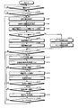
- FIG. 10 is a flowchart showing the flow of processing.
- FIG. 11 is a diagram illustrating a communication path according to the second embodiment.
- FIG. 12 is a diagram for explaining a correction example of the trajectory.
- FIG. 13 is an explanatory diagram illustrating an example of a computer that executes an input support program.
- FIG. 1 is a diagram illustrating an example of the overall configuration of a system according to the first embodiment.
- the input system shown in FIG. 1 includes a wearable device 10, a head mounted display 30, and an input device 50.
- the wearable device 10, the head mounted display 30, and the input device 50 are communicably connected via a network and can exchange various types of information.
- any type of communication network such as mobile communication such as a cellular phone, the Internet (Internet), a LAN (Local Area Network), a VPN (Virtual Private Network), or the like, regardless of wired or wireless. Can be adopted.
- a case where the wearable device 10, the head mounted display 30, and the input device 50 communicate by wireless communication will be described as an example.
- the input system is a system that supports user input.
- the input system is used for user work support in a factory or the like, and is used when the user takes notes or issues commands to other devices.
- a user may work while moving in various places. For this reason, by enabling various inputs using the wearable device 10 instead of a fixed terminal such as a personal computer, the user can input while moving in various places.
- Wearable device 10 is a device that a user wears and uses to detect a user's finger operation and gesture.
- the wearable device 10 is a device worn on a finger.
- the wearable device 10 functions as a pointer (pointing) device such as a mouse or an aerial handwriting input device.
- the wearable device 10 detects a change in the posture of the finger and transmits information related to the change in the posture of the finger to the input device 50.
- the case of functioning as a pointer device (pointing device) may be referred to as a pointer mode
- the case of functioning as an aerial handwriting input device may be referred to as a handwriting mode.
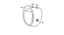
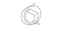
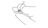
- FIGS. 2A to 2C are diagrams illustrating an example of a wearable device.
- the wearable device 10 has a ring shape like a ring, and can be attached to the finger by passing the finger through the ring as shown in FIG. 2C.
- a part of the ring is formed thicker and wider than the other part, and is a component built-in part that incorporates main electronic components.
- the wearable device 10 has a flat inner surface of a ring-containing component part. That is, the wearable device 10 has a shape that easily fits with a finger when the component built-in part is placed above the finger.
- the wearable device 10 is attached to the finger in a substantially similar orientation with the component built-in part on the upper side of the finger.
- the wearable device 10 is provided with a switch 14 on the side surface side of the ring.
- the wearable device 10 includes LED light emitting units 10a and 10b.
- the LED light emitting unit 10a emits red light
- the LED light emitting unit 10b emits green light.
- the switch 14 is disposed at a position corresponding to the thumb when the wearable device 10 is worn on the index finger of the right hand.
- the wearable device 10 is formed in a shape in which the peripheral portion of the switch 14 is raised to the same height as the upper surface of the switch 14. As a result, the wearable device 10 does not turn on the switch 14 simply by placing a finger on the switch 14 portion.
- FIG. 2D is a diagram illustrating an example of an operation on a wearable device switch.
- the example of FIG. 2D shows a case where the wearable device 10 is attached to the index finger and the switch 14 is operated with the thumb.
- the switch 14 is not turned on only by placing the thumb on the switch 14, and the switch 14 is turned on by pushing the thumb as shown on the right side of FIG. 2D.
- the user places the finger on the input position, and starts input by pushing the finger with the finger when performing input.
- the switch 14 is energized so that it is turned on when it is contracted, turned off when it is extended, and stretched by an elastic body such as a built-in spring. As a result, the switch 14 is turned on when it is pressed with a finger, and is turned off when the finger force is released. With this configuration, the wearable device 10 cannot start input unless it is worn in a normal state, and when it is worn on the finger, the wearing position is naturally corrected to a normal position. Further, the user can control the input / non-input section without releasing the finger from the switch 14.
- the head mounted display 30 is a device that is worn by the user on the head and displays various types of information so as to be visible to the user.
- the head mounted display 30 may be compatible with both eyes or may be compatible with only one eye.
- FIG. 3 is a diagram showing an example of a head mounted display.
- the head mounted display 30 has a glasses shape corresponding to both eyes.
- the head-mounted display 30 has transparency in the lens portion so that an external real environment can be visually recognized even when the user is wearing the head-mounted display 30.
- the head mounted display 30 includes a display unit having transparency in a part of the lens portion, and various types of information such as images can be displayed on the display unit.
- the head mounted display 30 realizes augmented reality in which the actual environment is expanded by visually recognizing various information in a part of the field of view while allowing the wearing user to visually recognize the actual environment.
- FIG. 3 schematically shows a display unit 30B provided in a part of the field of view 30A of the user who wears it.
- the head mounted display 30 has a built-in camera between two lens portions, and the camera can shoot an image in the line of sight of the user wearing the head mounted display 30.
- the input device 50 is a device that supports various inputs by user's finger operation.
- the input device 50 is a portable information processing device such as a smartphone or a tablet terminal.
- the input device 50 may be implemented as one or a plurality of computers provided in a data center or the like. That is, the input device 50 may be a cloud computer as long as it can communicate with the wearable device 10 and the head mounted display 30.
- Such an input system acquires motion information output from a motion sensor included in the wearable device 10.
- the input system uses the exercise information acquired during the period in which the switch 14 is input among the acquired exercise information, and obtains information corresponding to one of the operation modes of the first mode or the second mode. Output.
- the input system switches the operation mode to the other operation mode when the exercise information acquired during the period when the switch 14 is not input among the acquired exercise information satisfies a preset condition.
- the input system switches the currently selected operation mode to the other operation mode when the wearable device 10 moves a predetermined number of times with an acceleration equal to or greater than a predetermined value within a predetermined time. That is, the input system can switch the operation mode by moving the wearable device 10 without performing a switching operation of an application or the like on the display device side such as the head mounted display 30. Therefore, operability can be improved.
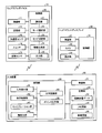
- FIG. 4 is a functional block diagram of the functional configuration of the system according to the first embodiment.
- functional configurations of the wearable device 10, the head mounted display 30, and the input device 50 will be described.
- the wearable device 10 includes a wireless unit 11, a storage unit 12, an acceleration sensor 13, a switch 14, a posture sensor 15, and a control unit 20.
- the wearable device 10 may have other devices other than the above devices.
- the wireless unit 11 is an interface that performs wireless communication control with other devices.
- a network interface card such as a wireless chip can be adopted.
- the wireless unit 11 is a device that communicates wirelessly, and transmits and receives various information to and from other devices wirelessly. For example, the wireless unit 11 transmits various information such as finger operation information and posture change information to the input device 50.
- the wireless unit 11 establishes two communication paths with the input device 50. Specifically, the wireless unit 11 transmits a pointer information transmission path using HID (Human Interface Device Profile), which is one of the standard profiles of Bluetooth (registered trademark), and a UserProfile (user) set in advance for handwriting input. Connect the route by profile.
- HID Human Interface Device Profile
- UserProfile User
- the storage unit 12 is a storage device that stores programs executed by the control unit 20 and various types of information, such as a hard disk or a memory.
- the storage unit 12 stores various information generated by the control unit 20, intermediate data of processing executed by the control unit 20, and the like.
- the acceleration sensor 13 is a sensor that detects the acceleration of the wearable device 10, and is, for example, a three-axis acceleration sensor. For example, the acceleration sensor 13 outputs the measured acceleration to the control unit 20.
- the switch 14 is a device that accepts input from the user.
- the switch 14 is provided on the side of the ring of the wearable device 10 as shown in FIG. 2C.
- the switch 14 is turned on when pressed, and turned off when released.
- the switch 14 receives an operation input from the user. For example, when the wearable device 10 is worn on the user's index finger, the switch 14 receives an operation input by the user's thumb.
- the switch 14 outputs operation information indicating the received operation content to the control unit 20.
- the user performs various inputs by operating the switch 14. For example, the user turns on the switch 14 when starting input by finger operation.
- the posture sensor 15 is a device that detects a user's finger operation, and is an example of a motion sensor.
- the attitude sensor 15 can employ a triaxial gyro sensor or the like.
- the posture sensor 15 is built in the wearable device 10 so that the three axes correspond to the rotation axis of the finger when the wearable device 10 is correctly attached to the finger.
- FIG. 5 is a diagram illustrating an example of a rotation axis of a finger. In the example of FIG. 5, three axes of X, Y, and Z that are orthogonal to each other are shown. In the example of FIG.
- the rotation axis in the movement direction for bending the finger is the Y axis
- the rotation axis in the movement direction for swinging the finger left and right is the Z axis
- the rotation axis in the movement direction for turning the finger is the X axis.
- the control unit 20 is a device that controls the wearable device 10.
- an integrated circuit such as a microcomputer, an ASIC (Application Specific Integrated Circuit), or an FPGA (Field Programmable Gate Array) can be employed.
- the control unit 20 transmits operation information of the switch 14 to the input device 50 via the wireless unit 11. Further, when the switch 14 is turned on, the control unit 20 controls the posture sensor 15 to detect a posture change. The control unit 20 transmits posture change information detected by the posture sensor 15 to the input device 50 via the wireless unit 11.
- Such a control unit 20 includes a detection unit 21, a mode selection unit 22, a mode switching unit 23, an information generation unit 24, and an output unit 25.
- the detection unit 21 is a processing unit that detects a sensor value output from the attitude sensor 15, that is, motion information. Specifically, the detection unit 21 sets the position at the time when the switch 14 is turned on as a reference, and continues to detect the movement history from the reference until the switch 14 turns from on to off, and the detected movement. The history is detected as exercise information. In addition, as a movement history, a coordinate and a triaxial gyroscope can also be used, and the information which combined a coordinate and a triaxial gyroscope can also be used. Moreover, the detection part 21 can also output the stop time etc. which a motion stopped, matched with the applicable location of exercise
- the mode selection unit 22 is a processing unit that selects either the pointer mode or the handwriting mode. For example, the mode selection unit 22 selects the pointer mode as the initial mode, and notifies the output unit 25 of information on the selected operation mode. Further, when switching is instructed by an instruction from a mode switching unit 23 described later, the mode selection unit 22 switches the selected operation mode to the other. For example, when the mode selection unit 22 receives a switching instruction while the pointer mode is selected, the mode selection unit 22 switches to the handwriting mode and notifies the output unit 25 of the switched operation mode.
- the initial mode can be arbitrarily changed.
- the mode switching unit 23 is a processing unit that switches the operation mode to the other operation mode when the motion information acquired in a period when the switch 14 is not input detects a preset operation. For example, the mode switching unit 23 notifies the mode selection unit 22 of a mode switching instruction when the acceleration of the wearable device 10 exceeds a predetermined value twice within one second, for example, in a state where the switch 14 is off. .
- the mode switching unit 23 when the mode switching unit 23 detects that the switch 14 is turned off, the mode switching unit 23 causes the wearable device 10 to transition to an idle state. That is, the mode switching unit 23 suppresses detection by the attitude sensor 15 when the switch 14 is off.
- the mode switching unit 23 from the idle state, after detecting an acceleration above a threshold value ( ⁇ (m / s 2) ) through an acceleration sensor 13, within one second, the threshold value ( ⁇ (m / s 2 )) A mode switching operation is detected when the above acceleration is detected again. Thereafter, the mode switching unit 23 outputs a mode switching instruction to the mode selection unit 22.
- the mode switching unit 23 can also notify the user of the mode being selected during the mode switching operation. For example, when the mode switching unit 23 detects an acceleration equal to or higher than the threshold value in the idle state, the mode switching unit 23 lights the LED light emitting unit 10a corresponding to the selected mode. Thereafter, when the mode switching unit 23 detects a mode switching operation, the other LED light emitting unit 10b emits light.
- the information generation unit 24 is a processing unit that extracts a series of exercise information from the exercise information received from the detection unit 21 until the switch 14 is turned on to off, and generates a movement locus of the finger. That is, the information generation unit 24 generates a movement locus by extracting a series of movement information about the movement of the finger in one segment until the switch 14 is turned on.
- the information generation unit 24 extracts a period from the start to the end of finger movement from the movement information received from the detection unit 21, extracts movement information within each period, and generates a movement locus of the finger. That is, the information generation unit 24 extracts a plurality of segments, extracts movement information for specifying a finger operation in each segment, and then generates a finger movement locus from a series of movement information.
- the information generation unit 24 sets the position where the switch 14 is turned on as a reference, and sets the position where the switch 14 is turned off as the end position. Then, the information generation unit 24 sets the reference to the start of the trajectory, and generates a trajectory connecting the start to the end position. Thereafter, the information generation unit 24 stores the generated trajectory information in the storage unit 12 in association with the generation time. Further, the information generation unit 24 outputs the generated trajectory information to the output unit 25.
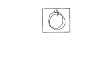
- FIG. 6 is a diagram illustrating an output example from the wearable device.
- the information generation unit 24 detects that the user's finger movement starts from “a”, pauses at “b”, and then further moves to “c”, and this a ⁇ b ⁇ c action Are extracted as exercise information. Subsequently, the information generation unit 24 extracts trajectory information by extracting a series of operations of a ⁇ b ⁇ c with reference to a. Furthermore, the information generation unit 24 extracts the trajectory of a ⁇ b and the trajectory of b ⁇ c to generate trajectory information.
- the output unit 25 is a processing unit that transmits the trajectory information generated by the information generation unit 24 to the input device 50 using the communication path corresponding to the selected operation mode. For example, when the operation mode is the pointer mode, the output unit 25 transmits the trajectory information generated by the information generation unit 24 to the input device 50 as pointer information. When the operation mode is the handwriting mode, the information generation unit 24 Is transmitted to the input device 50 as character information.
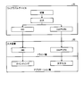
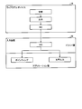
- FIG. 7 is a diagram for explaining a communication path.
- communication between the wearable device 10 and the input device 50 on the driver layer is established by both the route defined by the HID and the route defined by the UserProfile.
- the output unit 25 is switched to the pointer mode
- the trajectory information generated by the information generating unit 24 is transmitted via the HID, thereby transmitting the trajectory information to the input device 50 as pointer information. be able to.
- the information acquired by the input device 50 is handled as pointing processing in the application layer. That is, in the pointer mode, the locus of the user's finger is transmitted to the input device 50 in real time and then displayed on the head mounted display 30 in real time.
- the trajectory information can be transmitted as character information to the input device 50 by transmitting the trajectory information generated by the information generating unit 24 via the UserProfile. That is, in the handwriting mode, the locus of the user's handwriting operation is transmitted to the input device 50 in real time and then displayed on the head mounted display 30.
- the UserProfile is a communication protocol defined in advance between the wearable device 10 and the input device 50.
- the head mounted display 30 includes a wireless unit 31, a camera 32, a display unit 33, and a control unit 34.
- the head mounted display 30 may have other devices other than the above devices.
- the wireless unit 31 is a device that performs wireless communication.
- the wireless unit 31 transmits and receives various types of information to and from other devices wirelessly.
- the wireless unit 31 receives image information of an image to be displayed on the display unit 33 and an operation command instructing shooting from the input device 50.
- the wireless unit 31 transmits image information of an image captured by the camera 32 to the input device 50.
- the camera 32 is a device that captures an image. As shown in FIG. 3, the camera 32 is provided between two lens portions. The camera 32 captures an image under the control of the control unit 34.
- the display unit 33 is a device that displays various types of information. As shown in FIG. 3, the display unit 33 is provided in the lens portion of the head mounted display 30. The display unit 33 displays various information. For example, the display unit 33 displays a menu screen, a virtual laser pointer, an input locus, and the like.
- the control unit 34 is a device that controls the head mounted display 30.
- an electronic circuit such as a CPU (Central Processing Unit) or MPU (Micro Processing Unit), or an integrated circuit such as a microcomputer, ASIC, or FPGA can be employed.
- the control unit 34 performs control to display the image information received from the input device 50 on the display unit 33.
- the control unit 34 controls the camera 32 to photograph an image.
- the control unit 34 controls the wireless unit 31 to transmit the image information of the captured image to the input device 50.
- the input device 50 includes a wireless unit 51, a storage unit 52, and a control unit 60. Note that the input device 50 may include devices other than the above-described devices.
- the wireless unit 51 is a device that performs wireless communication.
- the wireless unit 51 transmits / receives various information to / from other devices wirelessly.
- the wireless unit 51 establishes two paths with the wearable device 10 and receives trajectory information (pointer information and character information), posture change information, and the like from the wearable device 10.
- the wireless unit 51 transmits image information, a pointer, and the like of an image to be displayed on the head mounted display 30 to the head mounted display 30.
- the wireless unit 51 receives image information of an image captured by the camera 32 of the head mounted display 30.
- the storage unit 52 is a storage device such as a hard disk, an SSD (Solid State Drive), or an optical disk.
- the storage unit 52 may be a semiconductor memory capable of rewriting data such as RAM (Random Access Memory), flash memory, NVSRAM (Non Volatile Static Random Access Memory).
- the storage unit 52 stores an OS (Operating System) and various programs executed by the control unit 60.
- the storage unit 52 stores various programs used for input support.
- the storage unit 52 stores various data used in programs executed by the control unit 60.
- the storage unit 52 stores recognition dictionary data 53, memo information 54, and image information 55.
- the recognition dictionary data 53 is dictionary data for recognizing handwritten characters.
- the recognition dictionary data 53 stores standard trajectory information of various characters.
- the memo information 54 is data storing information input by handwriting.
- an image of a character input by handwriting and character information obtained as a result of recognizing the character input by handwriting are stored in association with each other.
- the image information 55 is image information of an image taken by the camera 32 of the head mounted display 30.
- the control unit 60 is a device that controls the input device 50.
- an electronic circuit such as a CPU or MPU, or an integrated circuit such as a microcomputer, ASIC, or FPGA can be employed.
- the control unit 60 has an internal memory for storing programs defining various processing procedures and control data, and executes various processes using these.
- the control unit 60 functions as various processing units by operating various programs.
- the control unit 60 includes an input detection unit 61, a display control unit 62, a calibration unit 63, an axis detection unit 64, a character recognition unit 65, and a pointer output unit 66.
- the input detection unit 61 detects various inputs based on operation information and posture change information received from the wearable device 10. For example, the input detection unit 61 detects an operation on the switch 14 based on the operation information. For example, the input detection unit 61 detects single click, double click, triple click, and long press operation of the switch 14 from the number of times the switch 14 is pressed within a predetermined time. Further, the input detection unit 61 identifies the rotation of the three axes and the movement to each axis from the posture change information received from the wearable device 10, and detects the posture change of the finger.
- the display control unit 62 performs various display controls. For example, the display control unit 62 generates image information of various screens according to the detection result by the input detection unit 61, and transmits the generated image information to the head mounted display 30 via the wireless unit 51. As a result, an image of image information is displayed on the display unit 33 of the head mounted display 30. For example, when a double click is detected by the input detection unit 61, the display control unit 62 displays a menu screen on the display unit 33 of the head mounted display 30. The menu screen displays a menu for selecting an operation mode, a menu for calibration, and the like.
- the calibration unit 63 calibrates the detected posture information of the finger. For example, when the calibration mode is selected on the menu screen, the calibration unit 63 calibrates the detected finger posture information.
- the wearable device 10 may be worn in a misaligned state rotated in the circumferential direction with respect to the finger.
- the wearable device 10 When the wearable device 10 is worn in a shifted state with respect to a finger, there is a case where the posture change detected by the wearable device 10 is shifted by a rotation amount, and the detected motion may be different from the user's intention.
- the user selects the calibration mode on the menu screen.
- the user selects the calibration mode on the menu screen, the user opens and closes the hand on which the wearable device 10 is worn.
- the wearable device 10 transmits posture change information of the posture change of the finger when the hand is opened and closed to the input device 50.
- the calibration unit 63 detects the movement of the finger when the finger wearing the wearable device 10 is bent and stretched by opening and closing the hand based on the posture change information.
- the calibration unit 63 calibrates the reference direction of the finger movement based on the detected finger movement.
- the axis detection unit 64 detects the axis indicating the posture based on the posture change of the finger detected by the input detection unit 61. For example, the axis detection unit 64 detects an axis that moves in the direction according to a change in the posture of the finger. For example, the axis detector 64 passes through the origin in a three-dimensional space, and moves in the X, Y, and Z directions according to the respective rotation directions and rotation speeds of the X, Y, and Z rotation axes. The direction vector of is calculated. In addition, when detecting a motion only by a posture, it is difficult to move the wrist as far as it goes away from the facing direction. Further, when the palm is horizontal, the degree of freedom in the vertical direction is high, but the degree of freedom in the horizontal direction may be low.
- the axis detection unit 64 may change the vertical and left pointing sensitivity from the center point of the axis direction corrected by the calibration unit 63. For example, the axis detection unit 64 calculates the axis direction vector by correcting the rotation in the left-right direction of the hand to be larger than the rotation in the up-down direction of the hand. That is, when the rotation amount is the same, the axis detection unit 64 corrects the movement amount due to the rotation in the left-right direction larger than the movement amount due to the rotation in the vertical direction. Further, the axis detection unit 64 may increase the sensitivity as the distance from the center point in the corrected axis direction increases.
- the axis detection unit 64 calculates the axis direction vector by correcting the rotation to be greater as the distance from the center point in the axis direction increases. That is, when the rotation amount is the same, the axis detection unit 64 corrects the movement amount due to the rotation in the peripheral portion away from the center point in the axis direction larger than the movement amount due to the rotation near the center point. Thereby, since the sensitivity of rotation is set corresponding to the ease of movement of the wrist, accurate pointing can be facilitated.
- the character recognition unit 65 is a processing unit that executes character recognition in accordance with the trajectory information acquired from the wearable device 10. For example, the character recognition unit 65 recognizes the trajectory information acquired through the UserProfile as character information and compares it with standard trajectories of various characters stored in the recognition dictionary data 53. And the character recognition part 65 specifies the character with the highest similarity, and outputs the character code of the specified character. Further, the character recognition unit 65 displays the recognized character on the display unit 33 of the head mounted display 30 via the wireless unit 51.
- the character recognition unit 65 can perform character recognition again after correcting the locus specified from the locus information or the result of character recognition. For example, if there is “upper left splash” that is less frequently used in general Chinese characters, the character recognition unit 65 can also perform character recognition by deleting the locus corresponding to the hit.
- the user when the user performs handwritten input of characters, the user can also perform input by long pressing the switch 14 for each character. That is, the switch 14 is released once for each character. As a result, the trajectory information for each character is sent from the wearable device 10, so that the character recognition unit 65 can record the trajectory of handwriting input character by character and recognize the character from the trajectory character by character.
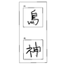
- FIG. 8 is a diagram illustrating an example of a display result of a locus of characters input by handwriting.
- FIG. 8A shows an example in which “bird” is input by handwriting.
- FIG. 8B is an example in which “God” is input by handwriting.
- the controller 60 makes it easy to recognize the character indicated by the trajectory by displaying the trajectory moving to the upper left in a lightly distinct manner.
- a thin line portion is indicated by a broken line.
- the character recognition unit 65 performs character recognition on the trajectory indicated by the dark line in FIGS. 8A to 8B.
- the character recognition unit 65 stores the locus, recognition result, character code, recognition execution time, and the like in the storage unit 52 in association with each other.
- the character recognition unit 65 stores the locus of handwritten characters and the recognized characters in the memo information 54.
- the character recognition unit 65 associates the trajectory information with the recognized character, and stores it in the memo information 54 together with the date / time information.
- Information stored in the memo information 54 can be referred to.
- the character recognition unit 65 displays information stored in the memo information 54 of the storage unit 52.
- the character recognizing unit 65 displays the input date and time of memo input, the text of the text recognizing the handwritten character, and the text of the handwritten character image in association with each other.
- the user can confirm whether the handwritten character is correctly recognized by displaying the sentence of the text and the sentence of the handwritten character image in association with each other.
- the user can refer to the corresponding character image even when the character is erroneously converted by the recognition of the trajectory. You can grasp the handwritten characters.
- the handwriting characteristics of the user are recorded in the handwritten character image. For this reason, the image of the handwritten character can also be stored and used for proof that the user has input, for example, like a signature.
- the pointer output unit 66 is a processing unit that displays pointer information according to the trajectory information acquired from the wearable device 10. For example, the pointer output unit 66 recognizes trajectory information acquired via the HID as pointer information. The pointer output unit 66 displays the recognized pointer information on the display unit 33 of the head mounted display 30 via the wireless unit 51. That is, the pointer output unit 66 displays the movement of the finger wearing the wearable device 10 as a pointer operation (gesture) of a mouse or the like on the display unit 33 of the head mounted display 30.
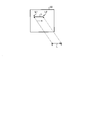
- FIG. 9 is a diagram illustrating an example of the operation of the pointer.
- the wearable device 10 moves to a point Y in the space after the switch 14 of the wearable device 10 attached to the finger is turned on at a point X in the space (trajectory L).
- the information generation unit 24 of the wearable device 10 generates trajectory information starting from the point X and ending at the point Y.
- the output unit 25 of the wearable device 10 transmits the trajectory information to the input device 50 via the HID.
- the pointer output unit 66 of the input device 50 recognizes this trajectory information as pointer information by receiving it through the HID.
- the pointer output unit 66 outputs a point L1 corresponding to the point X on the display unit 33 of the head mounted display 30, moves the locus L from the point L1, and outputs a point L2 corresponding to the point Y.
- the pointer displayed on the head mounted display 30 is displayed in synchronization with the trajectory information acquired from the wearable device 10 via the HID.
- a radar pointer may be output from the wearable device 10, and processing similar to that of a general computer mouse can be employed.
- the input device 50 may display coordinates or the like on the head mounted display 30, and the head mounted display 30 may display a pointer or the like at the corresponding coordinates.
- FIG. 10 is a flowchart showing the flow of processing.
- the detection unit 21 of the wearable device 10 detects the movement of the fingertip via the posture sensor 15 when the power is turned on (S101: Yes) and the switch 14 is also turned on (S102: Yes). (S103).
- the information generation unit 24 extracts a motion component (motion information) of finger operation (S104), and extracts a motion pattern (trajectory information) after the motion is started (S105). Then, when the operation mode is the handwriting mode (S106: Yes), the information generation unit 24 generates trajectory information (S107), and transmits the trajectory information to the input device 50 by communication using UserProfile (S108). ). On the other hand, when the operation mode is the pointer mode (S106: No), the information generation unit 24 generates pointer information from the trajectory information (S109), and transmits the pointer information to the input device 50 through communication using HID. (S110).
- the operation mode is the handwriting mode (S106: Yes
- the information generation unit 24 generates trajectory information (S107), and transmits the trajectory information to the input device 50 by communication using UserProfile (S108).
- the operation mode is the pointer mode (S106: No)
- the information generation unit 24 generates pointer information from the trajectory information (S109), and transmits the pointer information to
- the mode switching unit 23 repeats S112 and subsequent steps.
- the mode switching unit 23 notifies the user of the current operation mode (S115). Thereafter, when the mode switching unit 23 detects the acceleration again (S116), the mode switching unit 23 determines whether the detected acceleration is equal to or greater than a threshold value (S117).
- the mode switching unit 23 repeats S112 and subsequent steps.
- the mode switching unit 23 determines whether the elapsed time T is less than the threshold (S118). That is, it is determined whether the acceleration detected in S116 is detected within a predetermined time after the acceleration is detected in S113.
- the mode switching unit 23 repeats S112 and subsequent steps.
- the mode switching unit 23 changes the operation mode (S119).
- the communication path corresponding to each operation mode is isolated and various information can be output only by the path corresponding to the selected operation mode, the time for switching the path can be suppressed. In addition, it is possible to suppress mistransmissions of various information as compared with the case where only one route is used.
- the present invention is not limited to this.
- the same processing can be performed even when the wearable device 10 and the input device 50 are connected by one path.
- FIG. 11 is a diagram illustrating a communication path according to the second embodiment.
- the information generation unit 24 performs character recognition of the trajectory information using the generated trajectory information, recognition dictionary data, and the like. Then, the information generation unit 24 transmits a character code corresponding to the recognized character to the input device 50 through a route defined by the HID. That is, in the handwriting mode, the same processing as the character recognition unit 65 of the input device 50 is performed, and the recognition result is transmitted to the input device 50 in real time.
- the Bluetooth (registered trademark) standard profile described in the first and second embodiments is merely an example, and other standard profiles and communication formats may be employed.
- the information transmitted by the HID is not limited to the pointer information, and for example, information read by NFC (Near Field Communication) included in the wearable device 10 can be transmitted.
- a switch button for switching modes and an optical sensor are provided in the wearable device 10 and mode switching is performed when the switch button is pressed or when contact with another finger such as a thumb is detected by the optical sensor. You can also.
- the present invention is not limited to this, and exercise acquired during a period when the switch 14 is not input in the exercise information detected by the posture sensor 15.
- the operation mode can be switched when the information satisfies a preset condition.
- the wearable device 10 switches the operation mode when the exercise information acquired during a period when the switch 14 is not input matches the trajectory information specified in advance.
- FIG. 12 is a diagram for explaining an example of correction of a trajectory.
- the posture at which the switch 14 is turned on is set as the posture 0 point, and the estimated value of the finger posture change from the posture 0 point calculated based on the data after extracting the motion component of the finger operation is traced.
- the trajectory generation gain change profile is changed according to the posture change direction from the posture 0 point
- the trajectory generation gain change rate is changed according to the posture change amount from the posture 0 point
- the gain C of the posture 0 point is matched.
- a continuous function satisfying the above is assumed.
- the gain is increased with respect to the + Y-axis posture change with respect to the trajectory in the vertical axis direction, and the gain is increased with respect to the ⁇ Z-axis posture change with respect to the trajectory in the horizontal axis direction.
- a trajectory in a direction that is difficult to move can be processed in the same way as a trajectory in a direction that is easy to move, so that the trajectory can be accurately recognized.
- each component of each part illustrated does not necessarily need to be physically configured as illustrated.
- the specific form of distribution / integration of each unit is not limited to that shown in the figure, and all or a part thereof may be functionally or physically distributed / integrated in arbitrary units according to various loads or usage conditions. Can be configured.
- various processing functions performed by each device may be executed entirely or arbitrarily on a CPU (or a microcomputer such as an MPU or MCU (Micro Controller Unit)).
- various processing functions may be executed in whole or in any part on a program that is analyzed and executed by a CPU (or a microcomputer such as an MPU or MCU) or on hardware based on wired logic. Needless to say, it is good.
- FIG. 13 is an explanatory diagram illustrating an example of a computer that executes an input support program.
- the computer 300 includes a CPU 310, an HDD (Hard Disk Drive) 320, and a RAM (Random Access Memory) 340. These units 310 to 340 are connected via a bus 400.
- the HDD 320 includes an input support program 320a that exhibits the same functions as the detection unit 21, the mode selection unit 22, the mode switching unit 23, the information generation unit 24, and the output unit 25 of the wearable device 10, or the input detection unit of the input device 50. 61, a display control unit 62, a calibration unit 63, an axis detection unit 64, a character recognition unit 65, and an input support program 320a that performs the same functions as the pointer output unit 66 are stored in advance. Note that the input support program 320a may be separated as appropriate.
- the HDD 320 stores various information.
- the CPU 310 reads out and executes the input support program 320a from the HDD 320, thereby executing the same operation as each processing unit of the embodiment. That is, the input support program 320a is similar to the operation of the detection unit 21, the mode selection unit 22, the mode switching unit 23, the information generation unit 24, and the output unit 25, or the input detection unit 61, the display control unit 62, and the calibration. The operation similar to that of the operation unit 63, the axis detection unit 64, the character recognition unit 65, and the pointer output unit 66 is executed.
- the input support program 320a is not necessarily stored in the HDD 320 from the beginning.
- the program is stored in a “portable physical medium” such as a flexible disk (FD), a CD-ROM, a DVD disk, a magneto-optical disk, or an IC card inserted into the computer 300. Then, the computer 300 may read and execute the program from these.
- the program is stored in “another computer (or server)” connected to the computer 300 via a public line, the Internet, a LAN, a WAN, or the like. Then, the computer 300 may read and execute the program from these.
Landscapes
- Engineering & Computer Science (AREA)
- General Engineering & Computer Science (AREA)
- Theoretical Computer Science (AREA)
- Human Computer Interaction (AREA)
- Physics & Mathematics (AREA)
- General Physics & Mathematics (AREA)
- User Interface Of Digital Computer (AREA)
- Position Input By Displaying (AREA)
Abstract
La présente invention concerne un dispositif porté sur le corps qui est équipé d'un commutateur pour la réception d'une entrée, qui est porté sur un corps humain, et qui comporte un capteur d'attitude. Le dispositif porté sur le corps acquiert des informations de mouvement émises par le capteur d'attitude. Le dispositif porté sur le corps émet des informations correspondant à un premier mode ou à un deuxième mode, lesquels sont des modes de fonctionnement, au moyen des informations de mouvement qui sont incluses dans les informations de mouvement susmentionnées acquises du capteur d'attitude, et qui sont acquises lorsque le commutateur est activé. En outre, le dispositif porté sur le corps change de mode de fonctionnement si des informations de mouvement qui sont incluses dans les informations de mouvement susmentionnées acquises du capteur d'attitude, et qui sont acquises lorsque le commutateur est désactivé, satisfont à une condition prédéfinie.
Priority Applications (2)
| Application Number | Priority Date | Filing Date | Title |
|---|---|---|---|
| PCT/JP2016/052938 WO2017134732A1 (fr) | 2016-02-01 | 2016-02-01 | Dispositif d'entrée, procédé d'assistance à l'entrée, et programme d'assistance à l'entrée |
| JP2017564988A JPWO2017134732A1 (ja) | 2016-02-01 | 2016-02-01 | 入力装置、入力支援方法および入力支援プログラム |
Applications Claiming Priority (1)
| Application Number | Priority Date | Filing Date | Title |
|---|---|---|---|
| PCT/JP2016/052938 WO2017134732A1 (fr) | 2016-02-01 | 2016-02-01 | Dispositif d'entrée, procédé d'assistance à l'entrée, et programme d'assistance à l'entrée |
Publications (1)
| Publication Number | Publication Date |
|---|---|
| WO2017134732A1 true WO2017134732A1 (fr) | 2017-08-10 |
Family
ID=59500645
Family Applications (1)
| Application Number | Title | Priority Date | Filing Date |
|---|---|---|---|
| PCT/JP2016/052938 Ceased WO2017134732A1 (fr) | 2016-02-01 | 2016-02-01 | Dispositif d'entrée, procédé d'assistance à l'entrée, et programme d'assistance à l'entrée |
Country Status (2)
| Country | Link |
|---|---|
| JP (1) | JPWO2017134732A1 (fr) |
| WO (1) | WO2017134732A1 (fr) |
Cited By (6)
| Publication number | Priority date | Publication date | Assignee | Title |
|---|---|---|---|---|
| JP2020066110A (ja) * | 2018-10-25 | 2020-04-30 | 国立大学法人千葉大学 | 作業補助器具の制御方法 |
| JP2020173755A (ja) * | 2019-04-12 | 2020-10-22 | 未來市股▲ふん▼有限公司 | ユーザの手のジェスチャ又は手の動きを追跡すべきか否かを追跡ユニットに指示可能なヘッドマウントディスプレイシステム、関連する方法、関連するプログラム及び関連する非一時的なコンピュータ可読記憶媒体 |
| WO2021220867A1 (fr) * | 2020-04-28 | 2021-11-04 | 株式会社Nttドコモ | Dispositif de traitement d'informations |
| JP2022542845A (ja) * | 2019-07-31 | 2022-10-07 | サンブレイ テクノロジーズ ソシエダー リミターダ | 手装着データ入力装置 |
| CN115210659A (zh) * | 2021-02-04 | 2022-10-18 | 东芝三菱电机产业系统株式会社 | 工业工厂用操作辅助系统 |
| WO2023058325A1 (fr) * | 2021-10-05 | 2023-04-13 | ソニーグループ株式会社 | Dispositif de traitement d'informations, procédé de traitement d'informations et programme |
Citations (3)
| Publication number | Priority date | Publication date | Assignee | Title |
|---|---|---|---|---|
| JP2001236174A (ja) * | 2000-02-25 | 2001-08-31 | Fujitsu Ltd | 手書き文字入力装置及び手書き文字認識方法 |
| JP2008027082A (ja) * | 2006-07-19 | 2008-02-07 | Fujitsu Ltd | 手書き入力装置、手書き入力方法、及びコンピュータプログラム |
| JP2015090530A (ja) * | 2013-11-05 | 2015-05-11 | セイコーエプソン株式会社 | 画像表示システム、画像表示システムを制御する方法、および、頭部装着型表示装置 |
Family Cites Families (4)
| Publication number | Priority date | Publication date | Assignee | Title |
|---|---|---|---|---|
| JP2009301531A (ja) * | 2007-10-22 | 2009-12-24 | Sony Corp | 空間操作型入力装置、制御装置、制御システム、制御方法、空間操作型入力装置の製造方法及びハンドヘルド装置 |
| JP2010231736A (ja) * | 2009-03-30 | 2010-10-14 | Sony Corp | 入力装置および方法、情報処理装置および方法、情報処理システム、並びにプログラム |
| KR101943419B1 (ko) * | 2012-01-06 | 2019-01-30 | 삼성전자 주식회사 | 입력장치, 디스플레이장치, 그 제어방법 및 디스플레이 시스템 |
| JP2016009994A (ja) * | 2014-06-24 | 2016-01-18 | キヤノン株式会社 | 情報処理装置、情報処理装置の通信方法及びプログラム |
-
2016
- 2016-02-01 WO PCT/JP2016/052938 patent/WO2017134732A1/fr not_active Ceased
- 2016-02-01 JP JP2017564988A patent/JPWO2017134732A1/ja active Pending
Patent Citations (3)
| Publication number | Priority date | Publication date | Assignee | Title |
|---|---|---|---|---|
| JP2001236174A (ja) * | 2000-02-25 | 2001-08-31 | Fujitsu Ltd | 手書き文字入力装置及び手書き文字認識方法 |
| JP2008027082A (ja) * | 2006-07-19 | 2008-02-07 | Fujitsu Ltd | 手書き入力装置、手書き入力方法、及びコンピュータプログラム |
| JP2015090530A (ja) * | 2013-11-05 | 2015-05-11 | セイコーエプソン株式会社 | 画像表示システム、画像表示システムを制御する方法、および、頭部装着型表示装置 |
Cited By (9)
| Publication number | Priority date | Publication date | Assignee | Title |
|---|---|---|---|---|
| JP2020066110A (ja) * | 2018-10-25 | 2020-04-30 | 国立大学法人千葉大学 | 作業補助器具の制御方法 |
| JP2020173755A (ja) * | 2019-04-12 | 2020-10-22 | 未來市股▲ふん▼有限公司 | ユーザの手のジェスチャ又は手の動きを追跡すべきか否かを追跡ユニットに指示可能なヘッドマウントディスプレイシステム、関連する方法、関連するプログラム及び関連する非一時的なコンピュータ可読記憶媒体 |
| JP2022542845A (ja) * | 2019-07-31 | 2022-10-07 | サンブレイ テクノロジーズ ソシエダー リミターダ | 手装着データ入力装置 |
| JP7737649B2 (ja) | 2019-07-31 | 2025-09-11 | サンブレイ テクノロジーズ ソシエダー リミターダ | 手装着データ入力装置 |
| WO2021220867A1 (fr) * | 2020-04-28 | 2021-11-04 | 株式会社Nttドコモ | Dispositif de traitement d'informations |
| JPWO2021220867A1 (fr) * | 2020-04-28 | 2021-11-04 | ||
| JP7365501B2 (ja) | 2020-04-28 | 2023-10-19 | 株式会社Nttドコモ | 情報処理装置 |
| CN115210659A (zh) * | 2021-02-04 | 2022-10-18 | 东芝三菱电机产业系统株式会社 | 工业工厂用操作辅助系统 |
| WO2023058325A1 (fr) * | 2021-10-05 | 2023-04-13 | ソニーグループ株式会社 | Dispositif de traitement d'informations, procédé de traitement d'informations et programme |
Also Published As
| Publication number | Publication date |
|---|---|
| JPWO2017134732A1 (ja) | 2018-09-27 |
Similar Documents
| Publication | Publication Date | Title |
|---|---|---|
| US11157080B2 (en) | Detection device, detection method, control device, and control method | |
| US9983687B1 (en) | Gesture-controlled augmented reality experience using a mobile communications device | |
| JP6524661B2 (ja) | 入力支援方法、入力支援プログラムおよび入力支援装置 | |
| EP3090331B1 (fr) | Systèmes avec techniques pour une commande d'interface utilisateur | |
| KR102441328B1 (ko) | 이동 로봇이 전송한 화면을 표시하는 방법 및 그 전자장치 | |
| US20250093955A1 (en) | Input device, system, and control method | |
| WO2017134732A1 (fr) | Dispositif d'entrée, procédé d'assistance à l'entrée, et programme d'assistance à l'entrée | |
| US12158992B1 (en) | Systems for interpreting thumb movements of in-air hand gestures for controlling user interfaces based on spatial orientations of a user's hand, and method of use thereof | |
| WO2021035646A1 (fr) | Dispositif portable et son procédé de commande, procédé de reconnaissance de geste et système de commande | |
| KR100630806B1 (ko) | 동작 인식 장치를 이용한 명령 입력 방법 | |
| CN107896508A (zh) | 可以作为多个目标/端点(设备)和的整合点的以人为中心的“设备的超ui”体系结构的方法和设备,以及面向“模块化”通用控制器平台以及输入设备虚拟化的具有动态上下文意识的手势输入的相关方法/系统 | |
| US10372223B2 (en) | Method for providing user commands to an electronic processor and related processor program and electronic circuit | |
| JP2015142317A (ja) | 電子機器 | |
| CN108463789A (zh) | 信息处理设备、信息处理方法和程序 | |
| US20150253939A1 (en) | Information processing apparatus and information processing method | |
| JPWO2015104884A1 (ja) | 情報処理システム、情報処理方法およびプログラム | |
| US20250117091A1 (en) | Systems for interpreting a digit-to-digit gesture by a user differently based on roll values of a wrist-wearable device worn by the user, and methods of use thereof | |
| CN108369451B (zh) | 信息处理装置、信息处理方法及计算机可读存储介质 | |
| KR20240165372A (ko) | 사용자 인터페이스들의 개인화된 교정 | |
| US12197652B2 (en) | Control device and control method with set priorities for input operations in competitive relationship | |
| US20200348749A1 (en) | Information processing apparatus, information processing method, and program | |
| CN108369477B (zh) | 信息处理装置、信息处理方法和程序 | |
| JP6481360B2 (ja) | 入力方法、入力プログラムおよび入力装置 | |
| WO2017013805A1 (fr) | Dispositif d'entrée, procédé de support d'entrée et programme de support d'entrée | |
| US20240220097A1 (en) | Virtual mouse with tactile feedback provided via keyboard keys |
Legal Events
| Date | Code | Title | Description |
|---|---|---|---|
| 121 | Ep: the epo has been informed by wipo that ep was designated in this application |
Ref document number: 16889222 Country of ref document: EP Kind code of ref document: A1 |
|
| ENP | Entry into the national phase |
Ref document number: 2017564988 Country of ref document: JP Kind code of ref document: A |
|
| NENP | Non-entry into the national phase |
Ref country code: DE |
|
| 122 | Ep: pct application non-entry in european phase |
Ref document number: 16889222 Country of ref document: EP Kind code of ref document: A1 |