WO2017134737A1 - Appareil d'alimentation en fluide - Google Patents
Appareil d'alimentation en fluide Download PDFInfo
- Publication number
- WO2017134737A1 WO2017134737A1 PCT/JP2016/052992 JP2016052992W WO2017134737A1 WO 2017134737 A1 WO2017134737 A1 WO 2017134737A1 JP 2016052992 W JP2016052992 W JP 2016052992W WO 2017134737 A1 WO2017134737 A1 WO 2017134737A1
- Authority
- WO
- WIPO (PCT)
- Prior art keywords
- intake
- chamber
- liquid supply
- plunger
- supply device
- Prior art date
- Legal status (The legal status is an assumption and is not a legal conclusion. Google has not performed a legal analysis and makes no representation as to the accuracy of the status listed.)
- Ceased
Links
Images


Classifications
-
- A—HUMAN NECESSITIES
- A61—MEDICAL OR VETERINARY SCIENCE; HYGIENE
- A61M—DEVICES FOR INTRODUCING MEDIA INTO, OR ONTO, THE BODY; DEVICES FOR TRANSDUCING BODY MEDIA OR FOR TAKING MEDIA FROM THE BODY; DEVICES FOR PRODUCING OR ENDING SLEEP OR STUPOR
- A61M5/00—Devices for bringing media into the body in a subcutaneous, intra-vascular or intramuscular way; Accessories therefor, e.g. filling or cleaning devices, arm rests
- A61M5/14—Infusion devices, e.g. infusing by gravity; Blood infusion; Accessories therefor
- A61M5/142—Pressure infusion, e.g. using pumps
- A61M5/145—Pressure infusion, e.g. using pumps using pressurised reservoirs, e.g. by means of pistons
-
- F—MECHANICAL ENGINEERING; LIGHTING; HEATING; WEAPONS; BLASTING
- F04—POSITIVE - DISPLACEMENT MACHINES FOR LIQUIDS; PUMPS FOR LIQUIDS OR ELASTIC FLUIDS
- F04B—POSITIVE-DISPLACEMENT MACHINES FOR LIQUIDS; PUMPS
- F04B9/00—Piston machines or pumps characterised by the driving or driven means to or from their working members
Definitions
- the present invention relates to a liquid supply device that can be used as a chemical pump for supplying a chemical solution.
- the liquid injection device comprises a casing having a filling chamber filled with liquid, a moving body reciprocating with respect to the casing to increase or decrease the volume of the filling chamber, a cylinder connected to the casing or the moving body, a cylinder It is configured with a slidably mounted piston.
- An inlet and an outlet communicating with the filling chamber are formed in the casing, and a sealed cylinder chamber formed by movement of the piston with respect to the cylinder is in a vacuum state.
- the moving body and the piston are linked by the connecting rod and interlocked, and the volume of the filling chamber is reduced in proportion to the reduction of the volume of the cylinder chamber, whereby the liquid is discharged from the discharge port. .
- the flow rate adjustment per unit time of the liquid discharged from the discharge port is performed by operating the on-off valve device provided in the discharge port. That is, in the conventional liquid injection apparatus, the flow rate is adjusted by squeezing the discharge port depending on the degree of opening and closing of the on-off valve device.
- the viscosity of the liquid to be discharged changes, there is also a problem that the discharge flow rate of the liquid per unit time changes.
- the present invention has been made to solve such a problem, and an object of the present invention is to be able to supply a liquid at a stable discharge rate and to be able to finely adjust the discharge flow rate of the liquid. To provide a liquid supply device.
- an intake chamber and a contraction chamber are partitioned via a plunger that reciprocates in the axial direction inside a cylinder, and the liquid is drawn into the intake chamber.
- An apparatus for supplying a liquid by advancing the plunger by the pressure of air and reducing the volume of the contraction chamber, wherein an intake amount adjusting mechanism by fluid resistance is provided at an intake port communicating with the intake chamber It is characterized by
- the intake amount adjustment mechanism may be a flow control valve that changes a length of an intake passage from an intake hole to the intake port.
- the liquid storage pipe constituting the contraction chamber may be detachable from the cylinder.
- an open / close plate whose gap is increased or decreased by an open / close operation may be provided, and the open / close plate may be closed in accordance with the movement of the plunger.
- a shutoff valve that shuts off the intake port or the intake passage may be provided.
- a contraction chamber side piston provided at a tip end of the plunger and facing the contraction chamber is provided, and the intake amount adjustment mechanism is provided in an intake chamber facing the contraction chamber side piston. It may be done.
- a contraction chamber side piston provided at a tip end of the plunger and facing the contraction chamber, and an intake chamber side provided at a rear end of the plunger and facing the suction chamber
- the piston may be provided, and the plunger may be provided with a communication passage communicating from the first intake chamber facing the intake chamber side piston to the second intake chamber facing the contraction chamber side piston.
- the cylinder may be provided with an exhaust port communicating with the first intake chamber and a check valve for preventing backflow of air to the first intake chamber.
- the cylinder may be provided with an exhaust port communicating with the intake chamber and a check valve configured to prevent backflow of air to the intake chamber.
- the plunger may be supported by a spring.
- the intake amount adjusting mechanism using fluid resistance is provided at the intake port communicating with the intake chamber, the volume change of the contraction chamber can be absorbed without the influence of the viscosity of the liquid. Since it is possible to perform the flow control on the side, it is possible to supply the liquid at a stable discharge speed, and to finely adjust the discharge flow rate of the liquid in proportion to the operation amount of the intake amount adjustment mechanism. It has the effect of being able to
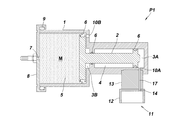
- FIG. 2 is a cross-sectional view showing the structure of the liquid supply device of Example 1;
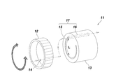
- FIG. 6 is a perspective view showing an example of an intake amount adjustment mechanism in the liquid supply device of the first embodiment.
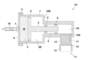
- FIG. 7 is a cross-sectional view showing the state of the liquid supply device of the first embodiment in operation.
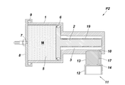
- FIG. 7 is a cross-sectional view showing the structure of the liquid supply device of Example 2;
- FIG. 13 is a cross-sectional view showing the structure of the liquid supply device of Example 3;
- FIG. 18 is a perspective view showing the mounting and demounting structure of the liquid storage pipe in the liquid supply device of the third embodiment.
- FIG. 14 is a cross-sectional view showing the structure of the liquid supply device of Example 4;
- FIG. 18 is a cross-sectional view showing the structure of the liquid supply device of Example 5; FIG. 18 is a cross-sectional view showing the structure of the liquid supply device of Example 6.
- FIG. 18 is a cross-sectional view showing the structure of the liquid supply device of Example 7;
- FIG. 21 is a cross-sectional view showing a structure of a liquid supply device of Example 8.
- FIG. 20 is a cross-sectional view showing the structure of the liquid supply device of Example 9.
- FIG. 21 is a cross-sectional view showing the structure of the liquid supply device of Example 10;
- FIG. 21 is a cross-sectional view showing the structure of the liquid supply device of Example 11.
- FIG. 21 is a cross-sectional view showing another application of the liquid supply device of Example 11.
- FIG. 1 shows a liquid supply apparatus P1 of the first embodiment.
- the apparatus P1 is a vacuum drive type chemical liquid pump and includes a cylinder 1 made of a transparent resin material and a plunger 2 made of a resin material, and the plunger 2 reciprocates in the axial direction (front and back) inside the cylinder 1 It is movably supported. Further, the space in the cylinder 1 is partitioned into two air intake chambers (first air intake chamber 3A, second air intake chamber 3B), a vacuum chamber 4 and a contraction chamber 5 via a plunger 2, The chamber is airtightly sealed by bringing rubber packings 6, 6, 6 into close contact with the inner peripheral surface of the cylinder 1.
- the raw material of the cylinder 1, the plunger 2, and the packing 6 is an example, and may be a thing other than the above.
- the contraction chamber 5 is a liquid accommodation space for accommodating the chemical solution M
- the lid 8 having the discharge port 7 is detachably attached to the opening of the contraction chamber 5 through the O-ring 9.
- the first air intake chamber 3A and the second air intake chamber 3B are gas suction spaces for sucking air from the outside of the apparatus, and two air intake ports (first air intake ports communicating with the first air intake chamber 3A)
- a second air intake port 10B communicating with the second air intake chamber 3B is formed.
- the first air intake port 10A is provided with an intake amount adjustment mechanism 11 utilizing fluid resistance.
- the second intake port 10B is a hole opened to bring the second intake chamber 3B to the atmospheric pressure.
- FIG. 2 shows an example of the intake amount adjustment mechanism 11.
- the intake amount adjustment mechanism 11 is a flow control valve capable of changing the length of a passage through which the air passes, and is configured to include a dial 12 and a grooved block 13.
- the dial 12 is a bottomed cylindrical body having an intake hole 14, and is disposed rotatably relative to the grooved block 13.
- an arc-shaped groove 15 is formed on the surface of a cylindrical block, and a through hole 16 is formed from the surface to the back surface of the block, and the groove 15 and the through hole 16 communicate with each other.
- One intake passage 17 is configured.
- the liquid supply device P1 of the first embodiment is configured as described above, and when the chemical solution M is first injected into the contraction chamber 5 at the time of use, the plunger 2 retracts and the volume of the contraction chamber 5 increases. Along with this, the volume of the vacuum chamber 4 also increases, but the volumes of the first intake chamber 3A and the second intake chamber 3B decrease.
- the opening of the contraction chamber 5 is closed with a lid 8 and sealed, and the tube 18 connected to the discharge port 7 is attached to the patient.
- the dial 12 of the flow control valve is turned to open the intake hole 14, the air taken in from the intake hole 14 passes through the intake passage 17 at a constant speed, and from the first intake port 10A to the first intake chamber 3A. Flow into. Then, as shown in FIG.
- the pressure in the first intake chamber 3A which was a negative pressure, is increased, so the pressure in the first intake chamber 3A is pushed and the volume of the vacuum chamber 4 is reduced.
- the advance reduces the volume of the contraction chamber 5.
- the discharge speed of the chemical solution M can be changed by the intake amount adjustment mechanism 11 provided in the first intake port 10A. That is, as shown in FIG. 2, the pipe resistance is changed by rotating the dial 12 of the flow control valve to extend and contract the length L of the groove 15, and the first intake port from the intake hole 14 through the intake passage 17 changes.
- the fluid resistance of the air flowing to 10 A changes. Therefore, the moving speed of the plunger 2 is controlled by adjusting the amount of air drawn from the first air inlet 10A to the first air intake chamber 3A.
- the discharge speed can be adjusted.
- the dial 12 is rotated to adjust the length of the intake passage 17 in comparison with the orifice resistance where the flow adjustment is difficult. Since the path resistance changes, there is an advantage that a linear flow rate characteristic proportional to the rotation angle of the dial 12 can be obtained.
- FIG. 4 shows a liquid supply device P2 of the second embodiment.
- the device P 2 is a spring-driven chemical pump, and a plunger 2 accommodated inside the cylinder 1 is supported by a spring 19.
- the space in the cylinder 1 is partitioned between the intake chamber 3 and the contraction chamber 5 via the plunger 2, and the space between the intake chamber 3 and the contraction chamber 5 is obtained by applying a negative pressure to the intake chamber 3.
- a pressure differential is provided.
- the other parts of the configuration are the same as those of the first embodiment, so the same reference numerals are given to the same members and the description will be omitted.
- the liquid supply device P2 of the second embodiment is configured as described above, and when the chemical solution M is injected into the contraction chamber 5, the plunger 2 is retracted against the spring force of the spring 19 and the volume of the intake chamber 3 is increased. Decrease.
- the spring 19 reduces the volume of the contraction chamber 5 and acts to increase the volume of the intake chamber 3.
- the intake chamber 3 has a negative pressure lower than the atmospheric pressure, and the pressure difference between the contraction chamber 5 and the atmospheric pressure acts on the contraction chamber side piston backward. The balance with the spring force of the spring 19 is maintained.
- the air taken in from the intake hole 14 passes through the intake passage 17 and flows into the intake chamber 3 and the intake chamber 3 has a negative pressure. Pressure increases. Therefore, the pressure of the intake chamber 3 is pushed by the spring force of the spring 19 to move the plunger 2 forward, and the volume of the contraction chamber 5 is reduced, whereby the chemical solution M having a constant flow rate is discharged from the discharge port 7 Ru.
- the moving speed of the plunger 2 can be controlled. Therefore, also in the liquid supply device P2 of the second embodiment, the discharge speed of the chemical solution M discharged from the discharge port 7 can be adjusted as in the first embodiment.
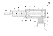
- FIG. 5 shows a liquid supply device P3 of the third embodiment.
- This apparatus P3 is a vacuum drive type chemical liquid pump, the space in the cylinder 1 is constituted by the intake chamber 3 and the vacuum chamber 4 via the plunger 2, the contraction chamber 5 is partitioned, and the contraction chamber 5 is A liquid storage pipe 20 is provided detachably to the cylinder 1.
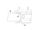
- the liquid medicine M is filled in advance inside the liquid storage pipe 20 and is sealed by closing the opening with a piston 21 having a packing 6. Further, as shown in FIG. 6, a flange 22 is formed on the periphery of the opening of the liquid storage tube 20, and the cylinder 1 is limited to the side (the left side of the vacuum chamber 4 in the drawing).
- the liquid supply device P3 of the third embodiment is configured as described above, and in use, the liquid storage pipe 20 in which the chemical solution M is sealed is attached to the cylinder 1 in advance.
- the flange 22 of the liquid storage tube 20 is fitted into the recess 23 of the cylinder 1 and then fixed by sliding.
- the intake hole 14 is opened by turning the dial 12 of the flow control valve, the air taken in from the intake hole 14 passes through the intake passage 17 and flows into the intake chamber 3.
- the chemical solution M having a constant flow rate is pushed out from the discharge port 7 by the piston 21.
- the moving speed of the plunger 2 can be controlled. Therefore, also in the liquid supply device P3 of the third embodiment, the discharge speed of the chemical solution M discharged from the discharge port 7 can be adjusted as in the first embodiment.
- the liquid storage pipe 20 is attachable to and detachable from the cylinder 1, the liquid medicine M can be exchanged easily and quickly, and the liquid medicine M can be used for the cylinder 1 and the plunger 2.
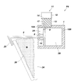
- FIG. 7 shows a liquid supply device P4 of the fourth embodiment.
- the device P4 is a spring-driven chemical pump, one end of which is accommodated inside the cylinder 1, and the other end of which is supported by a spring 19 with a plunger 2 projecting to the outside of the cylinder 1.
- the space in the cylinder 1 is partitioned between the first intake chamber 3A and the second intake chamber 3B via the plunger 2, and the first intake chamber 3A and the A pressure difference is provided between the two intake chambers 3B (atmospheric pressure).
- an open / close plate 24 is provided outside the cylinder 1 so as to integrally connect two resin plates so that the gap is increased or decreased by the open / close operation. Further, the connection portion of the opening and closing plate 24 may be connected via a hinge.
- the open / close plate 24 is closed by hook 25 of the plunger 2 so as to be closed when the plunger 2 is advanced and opened when the plunger 2 is retracted.
- the other parts of the configuration are the same as those of the first embodiment, so the same reference numerals are given to the same members and the description will be omitted.
- the liquid supply device P4 of the fourth embodiment is configured as described above, and at the time of use, the infusion bag 26 filled with the drug solution M is set in the gap of the open / close plate 24 as it is.
- the intake hole 14 is opened by turning the dial 12 of the flow rate adjustment valve, the air taken in from the intake hole 14 passes through the intake passage 17 and flows into the first intake chamber 3A, which is a negative pressure. Air flows into the single intake chamber 3A and the pressure rises. For this reason, the plunger 2 is advanced by being pushed by the pressure increase of the first intake chamber 3A and the spring force of the spring 19, and the volume of the second intake chamber 3B decreases.
- the open / close plate 24 is gradually closed, and the chemical solution M having a constant flow rate is supplied so as to be squeezed out from the infusion bag 26.
- the moving speed of the plunger 2 can be controlled. Therefore, according to the liquid supply apparatus P4 of the fourth embodiment, not only it is possible to adjust the supply speed of the drug solution M, but there is no need to transfer the drug solution M from the infusion bag 26 into the drug solution pump. Has the advantage of improving
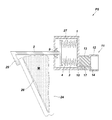
- FIG. 8 shows a liquid supply device P5 of the fifth embodiment.
- This apparatus P5 is in common with the fourth embodiment in that it comprises an open / close plate 24 which opens and closes interlockingly with the plunger 2, but it is a vacuum drive type chemical pump and comprises a bellows 27 in the cylinder 1.
- the fourth embodiment differs from the fourth embodiment in that That is, an expandable bellows 27 is attached to the tip of the plunger 2, and the open end of the bellows 27 is closely fixed to the inner wall surface of the cylinder 1. Further, the space in the cylinder 1 is partitioned between the suction chamber 3 outside the bellows 27 and the vacuum chamber 4 inside the bellows 27, and the suction chamber 3 has a negative pressure to make the suction chamber 3 and the vacuum chamber 4. There is a pressure difference between them.
- the other parts of the configuration are the same as those of the fourth embodiment, so the same reference numerals are given to the same members and the description will be omitted.
- the liquid supply device P5 of the fifth embodiment is configured as described above, and the infusion bag 26 filled with the drug solution M is set in the gap of the open / close plate 24, and the dial 12 of the flow control valve is turned to draw the intake hole 14
- the air taken in from the intake hole 14 passes through the intake passage 17 and flows into the intake chamber 3, and the pressure in the intake chamber 3 which is a negative pressure rises. Therefore, the pressure increase of the intake chamber 3 causes the bellows 27 to contract and the plunger 2 to move forward.
- the open / close plate 24 is gradually closed, and the chemical solution M having a constant flow rate is supplied so as to be squeezed out from the infusion bag 26.
- the moving speed of the plunger 2 can be controlled. Therefore, according to the liquid supply device P5 of the fifth embodiment, the same effect as that of the fourth embodiment can be obtained, and since the intake chamber 3 and the vacuum chamber 4 are completely separated by using the bellows 27, continuous use However, there is an advantage that malfunction due to air inflow can be prevented.
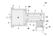
- FIG. 9 shows a liquid supply device P6 of the sixth embodiment.
- This device P6 is a vacuum drive type chemical liquid pump, and is characterized in that a shutoff valve 28 for shutting off the first air inlet 10A is provided. That is, in the intake amount adjustment mechanism 11 of the present embodiment, as shown in FIG. 9, a slide open / close shutoff valve 28 is embedded in the pipe of the intake passage 17 connected from the intake hole 14 to the first intake port 10A. It is done.
- the other parts of the configuration are the same as those of the first embodiment, so the same reference numerals are given to the same members and the description will be omitted.
- the liquid supply device P6 of the sixth embodiment is configured as described above, and the discharge amount is adjusted by adjusting the amount of air taken into the first intake chamber 3A by the intake amount adjustment mechanism 11 as in the first embodiment.
- the discharge speed of the drug solution M discharged from the outlet 7 can be adjusted.
- the shutoff valve 28 is closed during the discharge of the chemical solution M to shut off the first intake port 10A, air is not drawn into the first intake chamber 3A and the driving of the plunger 2 is stopped.
- the infusion operation can be interrupted at any timing.
- the shutoff valve 28 is opened to open the first intake port 10A, it is possible to resume the infusion operation at the same delivery speed as before the interruption.
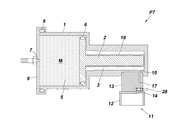
- FIG. 10 shows a liquid supply device P7 of the seventh embodiment.
- This apparatus P7 is similar to that of the sixth embodiment in that the shutoff valve 28 for shutting off the intake port 10 is provided, but it is a spring-driven chemical pump, and the plunger 2 housed inside the cylinder 1 Is different from the sixth embodiment in that it is supported by a spring 19.
- the other parts of the configuration are the same as those of the sixth embodiment, so the same reference numerals are given to the same members and the description will be omitted.
- the liquid supply device P7 of the seventh embodiment is configured as described above, and the discharge rate of the chemical solution M discharged from the discharge port 7 can be adjusted by the intake amount adjustment mechanism 11 as in the first embodiment. .
- the shutoff valve 28 for shutting off the intake port 10 has an advantage that the infusion operation can be interrupted or resumed at any timing.
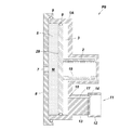
- FIG. 11 shows a liquid supply device P8 of the eighth embodiment.
- This apparatus P8 is a vacuum drive type chemical liquid pump, and the space in the cylinder 1A is divided into two intake chambers 3 (first intake chamber 3A, second intake chamber 3B), vacuum chamber 4 and contraction chamber via the plunger 2 Divided into five.
- a contraction chamber side piston 29 facing the contraction chamber 5 and the second intake chamber 3B is integrally provided at the tip end of the plunger 2, and a vacuum chamber 4 and a first intake chamber are provided at the rear end of the plunger 2
- An intake chamber side piston 30 facing the 3A is integrally provided.
- an intake amount adjustment mechanism 11 by the flow rate adjustment valve shown in FIG. 2 is provided in the intake port 10B communicating with the second intake chamber 3B.
- the other parts of the configuration are the same as those of the first embodiment, so the same reference numerals are given to the same members and the description will be omitted.
- the liquid supply device P8 of the eighth embodiment is configured as described above, and when the chemical solution M is injected into the contraction chamber 5 and the dial 12 of the flow control valve is turned to open the intake hole 14, it is drawn from the intake hole 14.
- the air passes through the intake passage 17 and flows into the second intake chamber 3B, and the pressure in the second intake chamber 3B increases.
- a force acts on the plunger 2 in the discharge direction due to the differential pressure between the vacuum pressure of the vacuum chamber 4 and the atmospheric pressure of the first intake chamber 3A.
- the second intake chamber 3B receives a force in the direction of volume increase in response to the force in the discharge direction of the plunger 2.
- the flow control valve when the flow control valve is closed, the negative pressure is lower than atmospheric pressure, and the plunger 2 It has stopped balance keeping. For this reason, the contraction chamber side piston 29 is pushed by receiving the pressure of the second intake chamber 3B, the plunger 2 advances, the volume of the contraction chamber 5 decreases, and the chemical solution M having a constant flow rate from the discharge port 7 It is discharged.
- the moving speed of the plunger 2 since the amount of air sucked from the intake port 10B to the second intake chamber 3B is adjusted by the intake amount adjustment mechanism 11, the moving speed of the plunger 2 can be controlled. Therefore, also in the liquid supply device P8 of the eighth embodiment, as in the first embodiment, the discharge speed of the chemical solution M discharged from the discharge port 7 can be adjusted.
- the entire size of the chemical solution pump becomes compact and there is an advantage that portability is improved.
- FIG. 12 shows a liquid supply device P9 of the ninth embodiment.
- This device P9 is common to the eighth embodiment in that it has a flat and thin cylinder 1A, but is a spring-driven chemical pump, and a plunger 2 accommodated inside the cylinder 1A is supported by a spring 19
- the eighth embodiment differs from the eighth embodiment in that Further, the space in the cylinder 1A is partitioned between the intake chamber 3 and the contraction chamber 5 via the plunger 2, and the pressure between the intake chamber 3 and the contraction chamber 5 is obtained by making the intake chamber 3 negative pressure. There is a difference.
- the other parts of the configuration are the same as those of the first embodiment, so the same reference numerals are given to the same members and the description will be omitted.
- the liquid supply device P9 according to the ninth embodiment is configured as described above, and the intake amount adjustment mechanism 11 is provided in the intake chamber 3 facing the contraction chamber side piston 29, as in the eighth embodiment.
- the discharge speed of the chemical solution M discharged from the discharge port 7 can be adjusted. Further, in the ninth embodiment, as in the eighth embodiment, by deforming into a flat and thin cylinder 1A which is wide in the radial direction, the whole size of the chemical solution pump becomes compact, and there is an advantage that portability is improved.
- FIG. 13 shows a liquid supply device P10 of the tenth embodiment.
- This apparatus P10 is a vacuum drive type chemical pump, and the space in the cylinder 1 is divided into two intake chambers 3 (first intake chamber 3A, second intake chamber 3B), vacuum chamber 4 and contraction chamber via a plunger 2 Divided into five.
- a contraction chamber side piston 29 facing the contraction chamber 5 and the second intake chamber 3B is integrally provided at the tip end of the plunger 2, and a vacuum chamber 4 and a first intake chamber are provided at the rear end of the plunger 2
- An intake chamber side piston 30 facing the 3A is integrally provided.
- a communication passage 31 communicating with the first intake chamber 3A to the second intake chamber 3B is provided at the center of the plunger 2, and the cylinder 1 is provided with an exhaust port 32 communicating with the first intake chamber 3A and A check valve 33 is provided to prevent backflow of air into the single intake chamber 3A.
- a check valve 33 an umbrella type or duckbill type check valve can be used.
- the other parts of the configuration are the same as those of the first embodiment, so the same reference numerals are given to the same members and the description will be omitted.
- the liquid supply device P10 is configured as described above, and the discharge rate of the chemical solution M discharged from the discharge port 7 can be adjusted by the intake amount adjustment mechanism 11 as in the first embodiment. .
- the air in the first intake chamber 3A can be rapidly exhausted through the check valve 33, and the chemical solution insertion operation can be easily performed.
- the vacuum pump 34 is attached to the exhaust port 32 via the check valve 33 and this vacuum pump 34 is driven to suck the air in the first intake chamber 3A.
- the air in the second intake chamber 3B is sucked through the communication passage 31.
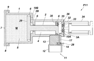
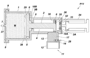
- FIG. 14 shows a liquid supply device P11 of the eleventh embodiment.
- This device P11 is a vacuum drive type chemical liquid pump, and not only the check valve 33 is provided in the cylinder 1, but also the exhaust port 35 communicating with the vacuum chamber 4 to the suction chamber side piston 30 and the vacuum chamber 4 A check valve 36 is provided to prevent backflow of air. Similar to the check valve 33, the check valve 36 can use an umbrella-type or duckbill-type check valve.
- the other parts of the configuration are the same as those of the tenth embodiment, so the same reference numerals are given to the same members and the description will be omitted.
- the liquid supply device P11 according to the eleventh embodiment is configured as described above, and as with the tenth embodiment, the discharge amount of the chemical solution M discharged from the discharge port 7 can be adjusted by the intake amount adjustment mechanism 11. . Further, particularly in the eleventh embodiment, when the vacuum pump 34 is attached to the exhaust port 32 via the check valve 33 and the vacuum pump 34 is driven to suck the air in the first intake chamber 3A, Since the air of the vacuum chamber 4 is also sucked, the degree of vacuum of the vacuum chamber 4 can be regenerated.
- the infusion bag 38 filled with the drug solution with the discharge joint 37 may be accommodated in the contraction chamber 5.
- the liquid medicine M can be easily replenished or replaced with a different kind of liquid medicine M simply by replacing the infusion bag 38, and the liquid medicine M does not touch the cylinder 1 or the plunger 2. Because there is no need for cleaning and disinfection, there is an advantage that it can be used always in a clean state.
- the application which accommodates the infusion solution bag 38 like FIG. 15 is similarly employable also in other Examples, for example, Example 1, 2, 6, 7, 8, 9, 10.
- medical solution pump was mentioned in the Example described above, the kind, viscosity, etc. of the liquid to supply such as an anesthetic solution, drip, a nutrient of stomach wax other than a chemical liquid It is not particularly limited. In addition to medical use, it can be used for an apparatus for supplying a liquid used in, for example, the fields of food, chemistry, and construction.
- P1 to P11 Liquid supply device (chemical solution pump) 1: Cylinder 2: Plunger 3: Intake chamber 3A: First intake chamber 3B: Second intake chamber 4: Vacuum chamber 5: Shrink chamber 6: Packing 7: Discharge port 8: Lid 9: O ring 10: Intake port 10A Reference: First intake port 10B: Second intake port 11: Intake volume adjustment mechanism 12: Dial 13: Block with groove 14: Intake hole 15: Groove 16: Through hole 17: Intake passage 18: Tube 19: Spring 20: Liquid accommodation Pipe 21: Piston 22: Flange 23: Recess 24: Opening and closing plate 25: Hook 26: Infusion bag 27: Bellows 28: Shut-off valve 29:shrinking chamber side piston 30: Intake chamber side piston 31: Communication passage 32: Exhaust port 33: Check valve 34: Vacuum pump 35: Exhaust port 36: Check valve 37: Discharge fitting 38: Infusion bag
Landscapes
- Engineering & Computer Science (AREA)
- Health & Medical Sciences (AREA)
- Animal Behavior & Ethology (AREA)
- General Health & Medical Sciences (AREA)
- Biomedical Technology (AREA)
- Heart & Thoracic Surgery (AREA)
- Hematology (AREA)
- Life Sciences & Earth Sciences (AREA)
- Vascular Medicine (AREA)
- Anesthesiology (AREA)
- Public Health (AREA)
- Veterinary Medicine (AREA)
- Mechanical Engineering (AREA)
- General Engineering & Computer Science (AREA)
- Reciprocating Pumps (AREA)
- Details Of Reciprocating Pumps (AREA)
- Infusion, Injection, And Reservoir Apparatuses (AREA)
Abstract
Le problème décrit par la présente invention est de fournir un appareil d'alimentation en fluide pouvant fournir un liquide à une vitesse d'évacuation stable et pouvant régler avec précision un débit d'évacuation du liquide. La solution selon l'invention porte sur un appareil d'alimentation en fluide P1, caractérisé en ce qu'une première chambre d'admission 3A, une seconde chambre d'admission 3B, une chambre à vide 4 et une chambre de contraction 5 sont formées séparément par l'intermédiaire d'un piston 2 qui se déplace en va-et-vient dans la direction axiale à l'intérieur d'un cylindre 1, l'appareil d'alimentation en fluide consistant en un appareil qui distribue un médicament liquide depuis un orifice d'évacuation 7 lorsque le piston 2 se déplace vers l'avant du fait de la pression de l'air aspiré dans la première chambre d'admission 3A, réduisant le volume de la chambre de contraction 5, un mécanisme de réglage 11 de quantité d'air d'admission en fonction d'une résistance de fluide étant agencé dans un premier orifice d'admission 10A relié à la première chambre d'admission 3.
Priority Applications (2)
| Application Number | Priority Date | Filing Date | Title |
|---|---|---|---|
| PCT/JP2016/052992 WO2017134737A1 (fr) | 2016-02-02 | 2016-02-02 | Appareil d'alimentation en fluide |
| JP2017564993A JP6652317B2 (ja) | 2016-02-02 | 2016-02-02 | 液体供給装置 |
Applications Claiming Priority (1)
| Application Number | Priority Date | Filing Date | Title |
|---|---|---|---|
| PCT/JP2016/052992 WO2017134737A1 (fr) | 2016-02-02 | 2016-02-02 | Appareil d'alimentation en fluide |
Publications (1)
| Publication Number | Publication Date |
|---|---|
| WO2017134737A1 true WO2017134737A1 (fr) | 2017-08-10 |
Family
ID=59500642
Family Applications (1)
| Application Number | Title | Priority Date | Filing Date |
|---|---|---|---|
| PCT/JP2016/052992 Ceased WO2017134737A1 (fr) | 2016-02-02 | 2016-02-02 | Appareil d'alimentation en fluide |
Country Status (2)
| Country | Link |
|---|---|
| JP (1) | JP6652317B2 (fr) |
| WO (1) | WO2017134737A1 (fr) |
Cited By (4)
| Publication number | Priority date | Publication date | Assignee | Title |
|---|---|---|---|---|
| JP2019069036A (ja) * | 2017-10-10 | 2019-05-09 | 入江工研株式会社 | 液体供給システム |
| CN111042967A (zh) * | 2018-10-15 | 2020-04-21 | 现代自动车株式会社 | 高压泵和压缩流体的方法 |
| JP2020526239A (ja) * | 2017-05-26 | 2020-08-31 | アンジオドロイド エス.アール.エル. | 血管造影法のためのガス造影剤の用量の調製し供給するための方法及びそのような方法を実現するデバイス |
| CN113404660A (zh) * | 2021-05-24 | 2021-09-17 | 中国十七冶集团有限公司 | 一种多用途增量泵 |
Citations (5)
| Publication number | Priority date | Publication date | Assignee | Title |
|---|---|---|---|---|
| JPH09173448A (ja) * | 1995-12-05 | 1997-07-08 | Smiths Ind Plc | 流体注入器 |
| JP2006283895A (ja) * | 2005-04-01 | 2006-10-19 | Toyota Motor Corp | 蓄圧装置 |
| JP2010536484A (ja) * | 2007-08-20 | 2010-12-02 | マリンクロッド・インコーポレイテッド | 流体駆動医用注射器 |
| JP2013192637A (ja) * | 2012-03-16 | 2013-09-30 | Terumo Corp | 薬液投与装置 |
| US20150335817A1 (en) * | 2014-05-24 | 2015-11-26 | Bio Health Frontiers, Incorporated | Pump apparatus, system and method of use |
-
2016
- 2016-02-02 WO PCT/JP2016/052992 patent/WO2017134737A1/fr not_active Ceased
- 2016-02-02 JP JP2017564993A patent/JP6652317B2/ja active Active
Patent Citations (5)
| Publication number | Priority date | Publication date | Assignee | Title |
|---|---|---|---|---|
| JPH09173448A (ja) * | 1995-12-05 | 1997-07-08 | Smiths Ind Plc | 流体注入器 |
| JP2006283895A (ja) * | 2005-04-01 | 2006-10-19 | Toyota Motor Corp | 蓄圧装置 |
| JP2010536484A (ja) * | 2007-08-20 | 2010-12-02 | マリンクロッド・インコーポレイテッド | 流体駆動医用注射器 |
| JP2013192637A (ja) * | 2012-03-16 | 2013-09-30 | Terumo Corp | 薬液投与装置 |
| US20150335817A1 (en) * | 2014-05-24 | 2015-11-26 | Bio Health Frontiers, Incorporated | Pump apparatus, system and method of use |
Cited By (5)
| Publication number | Priority date | Publication date | Assignee | Title |
|---|---|---|---|---|
| JP2020526239A (ja) * | 2017-05-26 | 2020-08-31 | アンジオドロイド エス.アール.エル. | 血管造影法のためのガス造影剤の用量の調製し供給するための方法及びそのような方法を実現するデバイス |
| JP7140404B2 (ja) | 2017-05-26 | 2022-09-21 | アンジオドロイド エス.アール.エル. | 血管造影法のためのガス造影剤の用量の調製し供給するための方法をコンピュータに実行させるためのコンピュータプログラム及びそのような方法を実現するデバイス |
| JP2019069036A (ja) * | 2017-10-10 | 2019-05-09 | 入江工研株式会社 | 液体供給システム |
| CN111042967A (zh) * | 2018-10-15 | 2020-04-21 | 现代自动车株式会社 | 高压泵和压缩流体的方法 |
| CN113404660A (zh) * | 2021-05-24 | 2021-09-17 | 中国十七冶集团有限公司 | 一种多用途增量泵 |
Also Published As
| Publication number | Publication date |
|---|---|
| JP6652317B2 (ja) | 2020-02-19 |
| JPWO2017134737A1 (ja) | 2018-11-22 |
Similar Documents
| Publication | Publication Date | Title |
|---|---|---|
| JP6802399B2 (ja) | 分離ピストン型定量ポンプ | |
| US10034977B2 (en) | Dosing device for an infusion system and method thereof | |
| CN101611227B (zh) | 容积泵 | |
| US4273121A (en) | Medical infusion system | |
| US8142397B2 (en) | Pump module method for a medical fluid dispensing system | |
| US8876765B2 (en) | Pump module for use in a medical fluid dispensing system | |
| AU2018397071B2 (en) | Micropump | |
| JPS6251764A (ja) | 制量ポンプ | |
| CN105612346A (zh) | 用于流体的体积泵送的旋转振荡子组件和旋转振荡体积泵送设备 | |
| JP6652317B2 (ja) | 液体供給装置 | |
| WO1995028977A1 (fr) | Dispositif d'injection de liquides | |
| US20050132879A1 (en) | Piston pump useful for aerosol generation | |
| US20230075848A1 (en) | Oscillatory-rotary liquid dispensing device with spring, and associated method | |
| CN111097082A (zh) | 输送计量器及输液装置 | |
| CN210003458U (zh) | 一种无阀正排量计量泵 | |
| EP2022982B1 (fr) | Pompe volumétrique | |
| CN119139577A (zh) | 一种药液供给装置及其使用方法 | |
| CN111375095A (zh) | 使用球囊作为用于往复式泵的端口的阻尼器 | |
| WO2015009623A1 (fr) | Pompe à piston à actionnement par came à chambres multiples |
Legal Events
| Date | Code | Title | Description |
|---|---|---|---|
| 121 | Ep: the epo has been informed by wipo that ep was designated in this application |
Ref document number: 16889227 Country of ref document: EP Kind code of ref document: A1 |
|
| ENP | Entry into the national phase |
Ref document number: 2017564993 Country of ref document: JP Kind code of ref document: A |
|
| NENP | Non-entry into the national phase |
Ref country code: DE |
|
| 122 | Ep: pct application non-entry in european phase |
Ref document number: 16889227 Country of ref document: EP Kind code of ref document: A1 |