WO2017134865A1 - Dispositif d'affichage tête haute - Google Patents
Dispositif d'affichage tête haute Download PDFInfo
- Publication number
- WO2017134865A1 WO2017134865A1 PCT/JP2016/081124 JP2016081124W WO2017134865A1 WO 2017134865 A1 WO2017134865 A1 WO 2017134865A1 JP 2016081124 W JP2016081124 W JP 2016081124W WO 2017134865 A1 WO2017134865 A1 WO 2017134865A1
- Authority
- WO
- WIPO (PCT)
- Prior art keywords
- display
- vehicle
- mirror
- display device
- head
- Prior art date
- Legal status (The legal status is an assumption and is not a legal conclusion. Google has not performed a legal analysis and makes no representation as to the accuracy of the status listed.)
- Ceased
Links
Images








Classifications
-
- G—PHYSICS
- G09—EDUCATION; CRYPTOGRAPHY; DISPLAY; ADVERTISING; SEALS
- G09G—ARRANGEMENTS OR CIRCUITS FOR CONTROL OF INDICATING DEVICES USING STATIC MEANS TO PRESENT VARIABLE INFORMATION
- G09G3/00—Control arrangements or circuits, of interest only in connection with visual indicators other than cathode-ray tubes
- G09G3/001—Control arrangements or circuits, of interest only in connection with visual indicators other than cathode-ray tubes using specific devices not provided for in groups G09G3/02 - G09G3/36, e.g. using an intermediate record carrier such as a film slide; Projection systems; Display of non-alphanumerical information, solely or in combination with alphanumerical information, e.g. digital display on projected diapositive as background
-
- G—PHYSICS
- G02—OPTICS
- G02B—OPTICAL ELEMENTS, SYSTEMS OR APPARATUS
- G02B27/00—Optical systems or apparatus not provided for by any of the groups G02B1/00 - G02B26/00, G02B30/00
- G02B27/01—Head-up displays
- G02B27/0101—Head-up displays characterised by optical features
-
- B—PERFORMING OPERATIONS; TRANSPORTING
- B60—VEHICLES IN GENERAL
- B60K—ARRANGEMENT OR MOUNTING OF PROPULSION UNITS OR OF TRANSMISSIONS IN VEHICLES; ARRANGEMENT OR MOUNTING OF PLURAL DIVERSE PRIME-MOVERS IN VEHICLES; AUXILIARY DRIVES FOR VEHICLES; INSTRUMENTATION OR DASHBOARDS FOR VEHICLES; ARRANGEMENTS IN CONNECTION WITH COOLING, AIR INTAKE, GAS EXHAUST OR FUEL SUPPLY OF PROPULSION UNITS IN VEHICLES
- B60K35/00—Instruments specially adapted for vehicles; Arrangement of instruments in or on vehicles
- B60K35/20—Output arrangements, i.e. from vehicle to user, associated with vehicle functions or specially adapted therefor
- B60K35/21—Output arrangements, i.e. from vehicle to user, associated with vehicle functions or specially adapted therefor using visual output, e.g. blinking lights or matrix displays
- B60K35/23—Head-up displays [HUD]
-
- B—PERFORMING OPERATIONS; TRANSPORTING
- B60—VEHICLES IN GENERAL
- B60K—ARRANGEMENT OR MOUNTING OF PROPULSION UNITS OR OF TRANSMISSIONS IN VEHICLES; ARRANGEMENT OR MOUNTING OF PLURAL DIVERSE PRIME-MOVERS IN VEHICLES; AUXILIARY DRIVES FOR VEHICLES; INSTRUMENTATION OR DASHBOARDS FOR VEHICLES; ARRANGEMENTS IN CONNECTION WITH COOLING, AIR INTAKE, GAS EXHAUST OR FUEL SUPPLY OF PROPULSION UNITS IN VEHICLES
- B60K35/00—Instruments specially adapted for vehicles; Arrangement of instruments in or on vehicles
- B60K35/20—Output arrangements, i.e. from vehicle to user, associated with vehicle functions or specially adapted therefor
- B60K35/28—Output arrangements, i.e. from vehicle to user, associated with vehicle functions or specially adapted therefor characterised by the type of the output information, e.g. video entertainment or vehicle dynamics information; characterised by the purpose of the output information, e.g. for attracting the attention of the driver
-
- B—PERFORMING OPERATIONS; TRANSPORTING
- B60—VEHICLES IN GENERAL
- B60K—ARRANGEMENT OR MOUNTING OF PROPULSION UNITS OR OF TRANSMISSIONS IN VEHICLES; ARRANGEMENT OR MOUNTING OF PLURAL DIVERSE PRIME-MOVERS IN VEHICLES; AUXILIARY DRIVES FOR VEHICLES; INSTRUMENTATION OR DASHBOARDS FOR VEHICLES; ARRANGEMENTS IN CONNECTION WITH COOLING, AIR INTAKE, GAS EXHAUST OR FUEL SUPPLY OF PROPULSION UNITS IN VEHICLES
- B60K35/00—Instruments specially adapted for vehicles; Arrangement of instruments in or on vehicles
- B60K35/50—Instruments characterised by their means of attachment to or integration in the vehicle
- B60K35/53—Movable instruments, e.g. slidable
-
- B—PERFORMING OPERATIONS; TRANSPORTING
- B60—VEHICLES IN GENERAL
- B60K—ARRANGEMENT OR MOUNTING OF PROPULSION UNITS OR OF TRANSMISSIONS IN VEHICLES; ARRANGEMENT OR MOUNTING OF PLURAL DIVERSE PRIME-MOVERS IN VEHICLES; AUXILIARY DRIVES FOR VEHICLES; INSTRUMENTATION OR DASHBOARDS FOR VEHICLES; ARRANGEMENTS IN CONNECTION WITH COOLING, AIR INTAKE, GAS EXHAUST OR FUEL SUPPLY OF PROPULSION UNITS IN VEHICLES
- B60K35/00—Instruments specially adapted for vehicles; Arrangement of instruments in or on vehicles
- B60K35/60—Instruments characterised by their location or relative disposition in or on vehicles
-
- B—PERFORMING OPERATIONS; TRANSPORTING
- B60—VEHICLES IN GENERAL
- B60K—ARRANGEMENT OR MOUNTING OF PROPULSION UNITS OR OF TRANSMISSIONS IN VEHICLES; ARRANGEMENT OR MOUNTING OF PLURAL DIVERSE PRIME-MOVERS IN VEHICLES; AUXILIARY DRIVES FOR VEHICLES; INSTRUMENTATION OR DASHBOARDS FOR VEHICLES; ARRANGEMENTS IN CONNECTION WITH COOLING, AIR INTAKE, GAS EXHAUST OR FUEL SUPPLY OF PROPULSION UNITS IN VEHICLES
- B60K35/00—Instruments specially adapted for vehicles; Arrangement of instruments in or on vehicles
- B60K35/80—Arrangements for controlling instruments
- B60K35/81—Arrangements for controlling instruments for controlling displays
-
- G—PHYSICS
- G01—MEASURING; TESTING
- G01C—MEASURING DISTANCES, LEVELS OR BEARINGS; SURVEYING; NAVIGATION; GYROSCOPIC INSTRUMENTS; PHOTOGRAMMETRY OR VIDEOGRAMMETRY
- G01C21/00—Navigation; Navigational instruments not provided for in groups G01C1/00 - G01C19/00
- G01C21/26—Navigation; Navigational instruments not provided for in groups G01C1/00 - G01C19/00 specially adapted for navigation in a road network
- G01C21/34—Route searching; Route guidance
- G01C21/36—Input/output arrangements for on-board computers
- G01C21/3626—Details of the output of route guidance instructions
- G01C21/365—Guidance using head up displays or projectors, e.g. virtual vehicles or arrows projected on the windscreen or on the road itself
-
- G—PHYSICS
- G02—OPTICS
- G02B—OPTICAL ELEMENTS, SYSTEMS OR APPARATUS
- G02B27/00—Optical systems or apparatus not provided for by any of the groups G02B1/00 - G02B26/00, G02B30/00
- G02B27/01—Head-up displays
-
- G—PHYSICS
- G02—OPTICS
- G02B—OPTICAL ELEMENTS, SYSTEMS OR APPARATUS
- G02B27/00—Optical systems or apparatus not provided for by any of the groups G02B1/00 - G02B26/00, G02B30/00
- G02B27/01—Head-up displays
- G02B27/0149—Head-up displays characterised by mechanical features
-
- G—PHYSICS
- G02—OPTICS
- G02B—OPTICAL ELEMENTS, SYSTEMS OR APPARATUS
- G02B30/00—Optical systems or apparatus for producing three-dimensional [3D] effects, e.g. stereoscopic images
- G02B30/50—Optical systems or apparatus for producing three-dimensional [3D] effects, e.g. stereoscopic images the image being built up from image elements distributed over a three-dimensional [3D] volume, e.g. voxels
- G02B30/52—Optical systems or apparatus for producing three-dimensional [3D] effects, e.g. stereoscopic images the image being built up from image elements distributed over a three-dimensional [3D] volume, e.g. voxels the three-dimensional [3D] volume being constructed from a stack or sequence of two-dimensional [2D] planes, e.g. depth sampling systems
-
- G—PHYSICS
- G09—EDUCATION; CRYPTOGRAPHY; DISPLAY; ADVERTISING; SEALS
- G09G—ARRANGEMENTS OR CIRCUITS FOR CONTROL OF INDICATING DEVICES USING STATIC MEANS TO PRESENT VARIABLE INFORMATION
- G09G3/00—Control arrangements or circuits, of interest only in connection with visual indicators other than cathode-ray tubes
- G09G3/001—Control arrangements or circuits, of interest only in connection with visual indicators other than cathode-ray tubes using specific devices not provided for in groups G09G3/02 - G09G3/36, e.g. using an intermediate record carrier such as a film slide; Projection systems; Display of non-alphanumerical information, solely or in combination with alphanumerical information, e.g. digital display on projected diapositive as background
- G09G3/002—Control arrangements or circuits, of interest only in connection with visual indicators other than cathode-ray tubes using specific devices not provided for in groups G09G3/02 - G09G3/36, e.g. using an intermediate record carrier such as a film slide; Projection systems; Display of non-alphanumerical information, solely or in combination with alphanumerical information, e.g. digital display on projected diapositive as background to project the image of a two-dimensional display, such as an array of light emitting or modulating elements or a CRT
-
- H—ELECTRICITY
- H04—ELECTRIC COMMUNICATION TECHNIQUE
- H04N—PICTORIAL COMMUNICATION, e.g. TELEVISION
- H04N9/00—Details of colour television systems
- H04N9/12—Picture reproducers
- H04N9/31—Projection devices for colour picture display, e.g. using electronic spatial light modulators [ESLM]
- H04N9/3179—Video signal processing therefor
- H04N9/3185—Geometric adjustment, e.g. keystone or convergence
-
- H—ELECTRICITY
- H04—ELECTRIC COMMUNICATION TECHNIQUE
- H04N—PICTORIAL COMMUNICATION, e.g. TELEVISION
- H04N9/00—Details of colour television systems
- H04N9/12—Picture reproducers
- H04N9/31—Projection devices for colour picture display, e.g. using electronic spatial light modulators [ESLM]
- H04N9/3191—Testing thereof
- H04N9/3194—Testing thereof including sensor feedback
-
- B—PERFORMING OPERATIONS; TRANSPORTING
- B60—VEHICLES IN GENERAL
- B60K—ARRANGEMENT OR MOUNTING OF PROPULSION UNITS OR OF TRANSMISSIONS IN VEHICLES; ARRANGEMENT OR MOUNTING OF PLURAL DIVERSE PRIME-MOVERS IN VEHICLES; AUXILIARY DRIVES FOR VEHICLES; INSTRUMENTATION OR DASHBOARDS FOR VEHICLES; ARRANGEMENTS IN CONNECTION WITH COOLING, AIR INTAKE, GAS EXHAUST OR FUEL SUPPLY OF PROPULSION UNITS IN VEHICLES
- B60K2360/00—Indexing scheme associated with groups B60K35/00 or B60K37/00 relating to details of instruments or dashboards
- B60K2360/20—Optical features of instruments
- B60K2360/23—Optical features of instruments using reflectors
-
- B—PERFORMING OPERATIONS; TRANSPORTING
- B60—VEHICLES IN GENERAL
- B60K—ARRANGEMENT OR MOUNTING OF PROPULSION UNITS OR OF TRANSMISSIONS IN VEHICLES; ARRANGEMENT OR MOUNTING OF PLURAL DIVERSE PRIME-MOVERS IN VEHICLES; AUXILIARY DRIVES FOR VEHICLES; INSTRUMENTATION OR DASHBOARDS FOR VEHICLES; ARRANGEMENTS IN CONNECTION WITH COOLING, AIR INTAKE, GAS EXHAUST OR FUEL SUPPLY OF PROPULSION UNITS IN VEHICLES
- B60K2360/00—Indexing scheme associated with groups B60K35/00 or B60K37/00 relating to details of instruments or dashboards
- B60K2360/20—Optical features of instruments
- B60K2360/33—Illumination features
- B60K2360/334—Projection means
-
- B—PERFORMING OPERATIONS; TRANSPORTING
- B60—VEHICLES IN GENERAL
- B60R—VEHICLES, VEHICLE FITTINGS, OR VEHICLE PARTS, NOT OTHERWISE PROVIDED FOR
- B60R2300/00—Details of viewing arrangements using cameras and displays, specially adapted for use in a vehicle
- B60R2300/20—Details of viewing arrangements using cameras and displays, specially adapted for use in a vehicle characterised by the type of display used
- B60R2300/205—Details of viewing arrangements using cameras and displays, specially adapted for use in a vehicle characterised by the type of display used using a head-up display
-
- B—PERFORMING OPERATIONS; TRANSPORTING
- B60—VEHICLES IN GENERAL
- B60R—VEHICLES, VEHICLE FITTINGS, OR VEHICLE PARTS, NOT OTHERWISE PROVIDED FOR
- B60R2300/00—Details of viewing arrangements using cameras and displays, specially adapted for use in a vehicle
- B60R2300/30—Details of viewing arrangements using cameras and displays, specially adapted for use in a vehicle characterised by the type of image processing
- B60R2300/307—Details of viewing arrangements using cameras and displays, specially adapted for use in a vehicle characterised by the type of image processing virtually distinguishing relevant parts of a scene from the background of the scene
- B60R2300/308—Details of viewing arrangements using cameras and displays, specially adapted for use in a vehicle characterised by the type of image processing virtually distinguishing relevant parts of a scene from the background of the scene by overlaying the real scene, e.g. through a head-up display on the windscreen
-
- G—PHYSICS
- G02—OPTICS
- G02B—OPTICAL ELEMENTS, SYSTEMS OR APPARATUS
- G02B27/00—Optical systems or apparatus not provided for by any of the groups G02B1/00 - G02B26/00, G02B30/00
- G02B27/01—Head-up displays
- G02B27/0101—Head-up displays characterised by optical features
- G02B2027/0123—Head-up displays characterised by optical features comprising devices increasing the field of view
-
- G—PHYSICS
- G02—OPTICS
- G02B—OPTICAL ELEMENTS, SYSTEMS OR APPARATUS
- G02B27/00—Optical systems or apparatus not provided for by any of the groups G02B1/00 - G02B26/00, G02B30/00
- G02B27/01—Head-up displays
- G02B27/0101—Head-up displays characterised by optical features
- G02B2027/014—Head-up displays characterised by optical features comprising information/image processing systems
-
- G—PHYSICS
- G02—OPTICS
- G02B—OPTICAL ELEMENTS, SYSTEMS OR APPARATUS
- G02B27/00—Optical systems or apparatus not provided for by any of the groups G02B1/00 - G02B26/00, G02B30/00
- G02B27/01—Head-up displays
- G02B27/0149—Head-up displays characterised by mechanical features
- G02B2027/0154—Head-up displays characterised by mechanical features with movable elements
-
- G—PHYSICS
- G02—OPTICS
- G02B—OPTICAL ELEMENTS, SYSTEMS OR APPARATUS
- G02B27/00—Optical systems or apparatus not provided for by any of the groups G02B1/00 - G02B26/00, G02B30/00
- G02B27/01—Head-up displays
- G02B27/0179—Display position adjusting means not related to the information to be displayed
- G02B2027/0187—Display position adjusting means not related to the information to be displayed slaved to motion of at least a part of the body of the user, e.g. head, eye
-
- G—PHYSICS
- G02—OPTICS
- G02B—OPTICAL ELEMENTS, SYSTEMS OR APPARATUS
- G02B27/00—Optical systems or apparatus not provided for by any of the groups G02B1/00 - G02B26/00, G02B30/00
- G02B27/64—Imaging systems using optical elements for stabilisation of the lateral and angular position of the image
-
- G—PHYSICS
- G09—EDUCATION; CRYPTOGRAPHY; DISPLAY; ADVERTISING; SEALS
- G09G—ARRANGEMENTS OR CIRCUITS FOR CONTROL OF INDICATING DEVICES USING STATIC MEANS TO PRESENT VARIABLE INFORMATION
- G09G2320/00—Control of display operating conditions
- G09G2320/06—Adjustment of display parameters
- G09G2320/0626—Adjustment of display parameters for control of overall brightness
-
- G—PHYSICS
- G09—EDUCATION; CRYPTOGRAPHY; DISPLAY; ADVERTISING; SEALS
- G09G—ARRANGEMENTS OR CIRCUITS FOR CONTROL OF INDICATING DEVICES USING STATIC MEANS TO PRESENT VARIABLE INFORMATION
- G09G2340/00—Aspects of display data processing
- G09G2340/04—Changes in size, position or resolution of an image
- G09G2340/0464—Positioning
-
- G—PHYSICS
- G09—EDUCATION; CRYPTOGRAPHY; DISPLAY; ADVERTISING; SEALS
- G09G—ARRANGEMENTS OR CIRCUITS FOR CONTROL OF INDICATING DEVICES USING STATIC MEANS TO PRESENT VARIABLE INFORMATION
- G09G2340/00—Aspects of display data processing
- G09G2340/04—Changes in size, position or resolution of an image
- G09G2340/0464—Positioning
- G09G2340/0471—Vertical positioning
-
- G—PHYSICS
- G09—EDUCATION; CRYPTOGRAPHY; DISPLAY; ADVERTISING; SEALS
- G09G—ARRANGEMENTS OR CIRCUITS FOR CONTROL OF INDICATING DEVICES USING STATIC MEANS TO PRESENT VARIABLE INFORMATION
- G09G2380/00—Specific applications
- G09G2380/10—Automotive applications
Definitions
- the present invention relates to a technology for a head-up display device, and more particularly, to a technology effective when applied to a head-up display device using AR (Augmented Reality).
- AR Augmented Reality
- HUD head-up display
- In-vehicle display devices including HUDs may cause the vehicle to vibrate or tilt depending on the driving situation, which may cause problems with the visibility of the displayed video or display appropriate content. .
- Patent Document 1 acquires a rotation component generated in a vehicle body as an inclination of the vehicle body, Based on this, it is described that the image is three-dimensionally corrected for rotation, and the position and inclination for displaying the rotation-corrected image are determined and projected.
- Patent Document 2 describes, when displaying the distance scale on the HUD, from the map data of the navigation device, the travel point information where the host vehicle is currently traveling, and the host vehicle Information on the planned travel point where the vehicle will travel, and based on this information, obtain the inclination angle of the road on which the vehicle travels, and use the correction coefficient according to the inclination angle to display the distance scale from the ground. It is described that the image is corrected and displayed.
- Patent Document 3 describes the display position of the generated image according to the detected driving situation such as right / left turn, acceleration / deceleration, and the like when left turn is detected. It is described that control is performed such as shifting to the right direction when a right turn is detected and shifting to the right direction.
- Patent Document 4 describes that the display position of video information is moved in a direction in which the driver's field of view is secured according to the vehicle state.
- JP 2013-237320 A JP 2007-55365 A JP 2006-7867 A JP2015-202842A
- HUD is to project a video on a windshield and to make the driver recognize the video as a virtual image outside the vehicle.
- a HUD that realizes a so-called AR function that makes it possible to show the driver information about the object or the like.
- AR-HUD Even in such an AR-HUD, it is necessary to make adjustments for maintaining the visibility and appropriateness of the display image in accordance with the traveling state of the vehicle.
- Patent Document 4 it is possible to move the display area itself in the HUD according to the vehicle state.
- the technique described in Patent Document 4 is intended to ensure the driver's field of view even when a change occurs in the vehicle state, so that the display area in the HUD does not become an obstacle to the driver. It is moved to a position.
- a virtual image may not be superimposed on an actual landscape included in the driver's field of view, and the AR function is not effective.
- an object of the present invention is to provide a head-up display device that can display a virtual image so as to be appropriately superimposed on an actual landscape in accordance with the traveling state of the vehicle.
- a head-up display device projects a video on a windshield of a vehicle, and displays a virtual image superimposed on a landscape in front of the vehicle for a driver.
- a vehicle information acquisition unit that acquires various types of vehicle information that can be detected by the vehicle, and a control unit that controls display of the video based on the vehicle information acquired by the vehicle information acquisition unit.
- An image display device that forms the image based on an instruction from the control unit, a mirror that reflects the image formed by the image display device and projects the image onto the windshield, and an instruction from the control unit
- a mirror driving unit that changes the angle of the mirror based on the display distance adjustment mechanism that adjusts a display distance of the virtual image to the driver. It is.
- the controller controls the angle of the mirror via the mirror driving unit so that the driver can display the virtual image superimposed on the landscape based on the vehicle information. adjust.
- the representative embodiment of the present invention it is possible to display the AR-HUD so as to appropriately superimpose the virtual image on the actual landscape according to the traveling state of the vehicle.
- (A), (b) is the figure which showed the outline
- (A), (b) is the figure which showed an example of the form of the navigation display in other one Embodiment of this invention.
- (A), (b) is the figure which showed an example of the form of the navigation display in other one Embodiment of this invention.
- (A), (b) is the figure which showed an example of the form of the navigation display in other one Embodiment of this invention. It is the figure which showed an example of the form of the navigation display in other one Embodiment of this invention.
- (A), (b) is the figure which showed an example of the form of the navigation display in other one Embodiment of this invention.
- (A), (b) is the figure which showed an example of the form of the navigation display in other one Embodiment of this invention.
- (A), (b) is the figure which showed an example of the form of the navigation display in other one Embodiment of this invention.
- (A), (b) is the figure which showed an example of the form of the navigation display in other one Embodiment of this invention.
- (A), (b), (c), (d) is the figure which showed an example of the form of the navigation display in other one Embodiment of this invention.
- (A), (b), (c), (d) is the figure which showed an example of the form of the navigation display in other one Embodiment of this invention.
- (A), (b), (c), (d) is the figure which showed an example of the form of the navigation display in other one Embodiment of this invention.
- (A), (b), (c) is a figure explaining operation
- FIG. 2 is a diagram showing an outline of an example of an operation concept of the head-up display device according to the embodiment of the present invention.
- an image displayed on the image display device 30 such as a projector or an LCD (Liquid Crystal Display) is converted into a mirror 51 or a mirror 52 (for example, a free-form surface mirror or an optical axis asymmetric shape). And is projected onto the windshield 3 of the vehicle 2.
- the driver 5 views the image projected as a virtual image in front of the transparent windshield 3 by viewing the image projected on the windshield 3.
- the display position of the virtual image seen by the driver 5 is adjusted in the vertical direction by adjusting the position of the image projected onto the windshield 3 by adjusting the angle of the mirror 52.
- the display distance can be adjusted, such as displaying a virtual image near (for example, 2 to 3 m away) or distant (for example, 30 to 40 m away). It is.
- the AR function is realized by adjusting the display position and the display distance so that the virtual image is superimposed on the scenery outside the vehicle (roads, buildings, people, etc.).
- FIG. 1 is a functional block diagram showing an outline of an overall configuration example of a head-up display device according to an embodiment of the present invention.
- the AR-HUD 1 mounted on the vehicle 2 includes, for example, a vehicle information acquisition unit 10, a control unit 20, a video display device 30, a display distance adjustment mechanism 40, a mirror driving unit 50, a mirror 52, and a speaker 60.
- the shape of the vehicle 2 is displayed like a passenger car.
- the shape of the vehicle 2 is not particularly limited, and can be applied as appropriate to general vehicles.
- the vehicle information acquisition unit 10 includes information acquisition devices such as various sensors, which will be described later, installed in each part of the vehicle 2, detects various events occurring in the vehicle 2, and relates to the driving situation at predetermined intervals.
- the vehicle information 4 is acquired and output by detecting and acquiring values of various parameters.
- the vehicle information 4 includes, for example, speed information, gear information, steering wheel steering angle information, lamp lighting information, external light information, distance information, infrared information, engine ON / OFF information, and camera video information of the vehicle 2 as illustrated. (Inside / outside the vehicle), acceleration gyro information, GPS (Global Positioning System) information, navigation information, vehicle-to-vehicle communication information, road-to-vehicle communication information, and the like may be included.
- the control unit 20 has a function of controlling the operation of the AR-HUD 1, and is implemented by, for example, a CPU (Central Processing Unit) and software executed thereby. It may be implemented by hardware such as a microcomputer or FPGA (Field Programmable Gate Array). As shown in FIG. 2, the control unit 20 drives the video display device 30 to form an image to be displayed as a virtual image based on the vehicle information 4 acquired from the vehicle information acquisition unit 10, and this is mirrored. The light is projected onto the windshield 3 by being appropriately reflected by 52 or the like. Then, control such as adjusting the display position of the virtual image display area or adjusting the display distance of the virtual image is performed by a method described later.
- a CPU Central Processing Unit
- FPGA Field Programmable Gate Array
- the video display device 30 is a device configured by, for example, a projector or an LCD, and forms a video for displaying a virtual image based on an instruction from the control unit 20 and projects or displays the video.
- the display distance adjustment mechanism 40 is a mechanism for adjusting the distance from the driver 5 of the virtual image to be displayed based on an instruction from the control unit 20. For example, various display distance adjustment methods as described later are used. One or more of them are mounted.
- the mirror driving unit 50 adjusts the angle of the mirror 52 based on an instruction from the control unit 20 and adjusts the position of the virtual image display area in the vertical direction. The adjustment of the position of the virtual image display area will be described later.
- the speaker 60 performs audio output related to the AR-HUD1. For example, voice guidance of the navigation system, voice output when notifying the driver 5 by the AR function, etc. can be performed.
- FIG. 3 is a diagram showing an outline of an example of a hardware configuration related to acquisition of the vehicle information 4 in the head-up display device of the present embodiment.
- the vehicle information 4 is acquired by an information acquisition device such as various sensors connected to the ECU 21 under the control of an ECU (Electronic Control Unit) 21, for example.
- ECU Electronic Control Unit
- a vehicle speed sensor 101 for example, a vehicle speed sensor 101, a shift position sensor 102, a steering wheel steering angle sensor 103, a headlight sensor 104, an illuminance sensor 105, a chromaticity sensor 106, a distance measuring sensor 107, an infrared sensor 108, an engine start sensor 109, acceleration sensor 110, gyro sensor 111, temperature sensor 112, road-to-vehicle communication wireless receiver 113, vehicle-to-vehicle communication wireless receiver 114, camera (inside the vehicle) 115, camera (outside the vehicle) 116, GPS receiver 117, and
- Each device includes a VICS (Vehicle Information and Communication System: a road traffic information communication system, registered trademark (hereinafter the same)) receiver 118 and the like. It is not always necessary to include all these devices, and other types of devices may be included.
- the vehicle information 4 that can be acquired by the provided device can be used as appropriate.
- the vehicle speed sensor 101 acquires speed information of the vehicle 2.
- the shift position sensor 102 acquires current gear information of the vehicle 2.
- the steering wheel angle sensor 103 acquires steering wheel angle information.
- the headlight sensor 104 acquires lamp lighting information related to ON / OFF of the headlight.
- the illuminance sensor 105 and the chromaticity sensor 106 acquire external light information.
- the distance measuring sensor 107 acquires distance information between the vehicle 2 and an external object.
- the infrared sensor 108 acquires infrared information related to the presence / absence and distance of an object at a short distance of the vehicle 2.
- the engine start sensor 109 detects engine ON / OFF information.
- the acceleration sensor 110 and the gyro sensor 111 acquire acceleration gyro information including acceleration and angular velocity as information on the posture and behavior of the vehicle 2.
- the temperature sensor 112 acquires temperature information inside and outside the vehicle.
- the road-to-vehicle communication wireless receiver 113 and the vehicle-to-vehicle communication wireless receiver 114 are respectively road-to-vehicle communication information received by road-to-vehicle communication between the vehicle 2 and roads, signs, signals, etc.
- the vehicle-to-vehicle communication information received by the vehicle-to-vehicle communication with another vehicle is acquired.
- the camera (inside the vehicle) 115 and the camera (outside the vehicle) 116 respectively capture the moving image of the situation inside and outside the vehicle and acquire camera video information (inside / outside the vehicle).
- the camera (inside the vehicle) 115 captures, for example, the posture of the driver 5, the position of the eyes, the movement, and the like. By analyzing the obtained moving image, for example, it is possible to grasp the fatigue status of the driver 5, the position of the line of sight, and the like.
- the camera (outside the vehicle) 116 captures a situation around the vehicle 2 such as the front or rear. By analyzing the obtained video, for example, it is possible to grasp the presence or absence of moving objects such as other vehicles and people around the building, topography, road surface conditions (rain, snow, freezing, unevenness, etc.) It is.
- the GPS receiver 117 and the VICS receiver 118 obtain GPS information obtained by receiving the GPS signal and VICS information obtained by receiving the VICS signal, respectively. It may be implemented as a part of a car navigation system that acquires and uses these pieces of information.
- FIG. 4 is a functional block diagram showing details of a configuration example of the head-up display device of the present embodiment.
- the example of FIG. 4 shows a case where the video display device 30 is a projector, and the video display device 30 includes, for example, each unit such as a light source 31, an illumination optical system 32, and a display element 33.
- the light source 31 is a member that generates illumination light for projection.
- a high-pressure mercury lamp, a xenon lamp, an LED (Light-Emitting-Diode) light source, a laser light source, or the like can be used.
- the illumination optical system 32 is an optical system that collects the illumination light generated by the light source 31 and irradiates the display element 33 with more uniform illumination light.
- the display element 33 is an element that generates an image to be projected.
- a transmissive liquid crystal panel, a reflective liquid crystal panel, a DMD (Digital Micromirror Device) (registered trademark) panel, or the like can be used.
- control unit 20 includes an ECU 21, an audio output unit 22, a nonvolatile memory 23, a memory 24, a light source adjustment unit 25, a distortion correction unit 26, a display element drive unit 27, a display distance adjustment unit 28, and a mirror adjustment. Each part such as the part 29 is included.
- the ECU 21 acquires the vehicle information 4 via the vehicle information acquisition unit 10, and records, stores, and reads the acquired information in the nonvolatile memory 23 and the memory 24 as necessary. To do.
- the nonvolatile memory 23 may store setting information such as setting values and parameters for various controls. Further, the ECU 21 generates video data relating to a virtual image to be displayed as the AR-HUD 1 by executing a dedicated program.
- the audio output unit 22 outputs audio information via the speaker 60 as necessary.
- the light source adjustment unit 25 adjusts the light emission amount of the light source 31 of the video display device 30. When there are a plurality of light sources 31, they may be controlled individually.
- the distortion correction unit 26 corrects the video distortion caused by the curvature of the windshield 3 by image processing.
- the display element drive unit 27 sends a drive signal corresponding to the video data corrected by the distortion correction unit 26 to the display element 33 to generate an image to be projected.
- the display distance adjustment unit 28 drives the display distance adjustment mechanism 40 to adjust the display distance of the image projected from the image display device 30.
- the mirror adjustment unit 29 changes the angle of the mirror 52 via the mirror driving unit 50 to move the virtual image display area up and down. The position adjustment of the virtual image display area will also be described later.
- FIG. 5 is a diagram showing details of an example of a configuration related to display distance adjustment in the head-up display device of the present embodiment.
- the display distance adjustment unit 28 of the control unit 20 further includes, as individual units controlled by the ECU 21, for example, a functional liquid crystal film ON / OFF control unit 281, a lens movable unit 282, and a dimming mirror ON / OFF control unit 283. , A diffusion plate movable portion 284, an optical filter movable portion 285, and the like.
- the display distance adjustment mechanism 40 further includes a functional liquid crystal film 401, a lens movable mechanism 402, a light control mirror 403, a diffusion plate movable mechanism 404, and an optical.
- a filter movable mechanism 405 and the like are included. A method for adjusting the display distance of the virtual image by these units will be described later.
- the AR-HUD 1 does not need to include all of these units and devices, but may include various units necessary for implementing the virtual image display distance adjustment method described later. Good.
- FIG. 6 is a flowchart showing an outline of an example of an initial operation of the head-up display device of the present embodiment.
- the AR-HUD 1 starts with the vehicle information acquisition unit 10 based on an instruction from the control unit 20.
- vehicle information is acquired (S02).
- the control unit 20 calculates a suitable brightness level based on external light information acquired by the illuminance sensor 105, the chromaticity sensor 106, and the like in the vehicle information 4 (S03), and the light source adjustment unit 25 calculates the light source 31. Is set so that the calculated brightness level is obtained (S04). For example, when the outside light is bright, the brightness level is set high, and when the outside light is dark, the brightness level is set low.
- the ECU 21 determines and generates a video (for example, an initial image) to be displayed as a virtual image (S05), and performs a process of correcting the distortion by the distortion correction unit 26 for the generated video (S06).
- the display element 33 is driven and controlled by the element driving unit 27 to form a projected image (S07).
- video is projected on the windshield 3, and the driver
- the ECU 21 or the display distance adjustment unit 28 calculates and determines the display distance of the virtual image (S08), and the display distance adjustment unit 28 drives the display distance adjustment mechanism 40 to display the image projected from the video display device 30.
- the distance is controlled (S09).
- the HUD-ON signal is output.
- the control unit 20 determines whether or not this signal has been received (S11). . If not received, the HUD-ON signal is further waited for a predetermined time (S12), and the HUD-ON signal waiting process (S12) is repeated until it is determined in step S11 that the HUD-ON signal has been received. If it is determined in step S11 that the HUD-ON signal has been received, normal operation of AR-HUD1 described later is started (S13), and a series of initial operations are terminated.
- FIG. 7 is a flowchart showing an outline of an example of normal operation of the head-up display device of the present embodiment. Also in the normal operation, the basic processing flow is substantially the same as the initial operation shown in FIG. First, the AR-HUD 1 acquires vehicle information by the vehicle information acquisition unit 10 based on an instruction from the control unit 20 (S21). And the control part 20 performs a brightness level adjustment process based on the external light information acquired by the illumination intensity sensor 105, the chromaticity sensor 106, etc. among the vehicle information 4 (S22).
- FIG. 8 is a flowchart showing an outline of an example of brightness level adjustment processing of the head-up display device of the present embodiment.
- a suitable brightness level is calculated based on the acquired outside light information (S221). Then, by comparing with the currently set brightness level, it is determined whether or not the brightness level needs to be changed (S222). If no change is necessary, the brightness level adjustment process is terminated. On the other hand, when the change is necessary, the light source adjustment unit 25 controls the light emission amount of the light source 31 to set the brightness level after the change (S223), and the brightness level adjustment process is ended. .
- step S222 even when there is a difference between the preferred brightness level calculated in step S221 and the currently set brightness level, the brightness level is only when the difference is equal to or greater than a predetermined threshold. It may be determined that the change is necessary.
- the video displayed as a virtual image is changed as necessary from the current one based on the latest vehicle information 4 acquired in step S ⁇ b> 21, and the changed video is determined and generated.
- the pattern which changes a display content based on the vehicle information 4 can have many things according to the content of the acquired vehicle information 4, those combinations, etc. For example, when the speed information changes, the value of the speed display that is displayed at all times is changed, the guidance arrow graphic is displayed / erased based on the navigation information, and the arrow shape and display position are changed. There may be various patterns, such as when performing.
- adjustment / correction processing is performed to maintain visibility, appropriateness of display contents, and the like according to the traveling state of the vehicle 2.
- the mirror adjustment process is performed to change the angle of the mirror 52 via the mirror driving unit 50 and move the virtual image display area up and down (S24).
- a vibration correction process for correcting the display position of the image in the display area with respect to the vibration of the vehicle 2 is performed (S25). Detailed contents of the adjustment / correction processing in steps S24 and S25 will be described later.
- the distortion correction unit 26 performs distortion correction processing on the adjusted / corrected image (S26), and then the display element driving unit 27 drives and controls the display element 33 to form a projected image ( S27). Then, the display distance adjustment unit 28 calculates and determines the display distance of the virtual image (S28), and the display distance adjustment unit 28 drives the display distance adjustment mechanism 40 to display the image projected from the image display device 30. The distance is controlled (S29).
- a HUD-OFF signal is output to the AR-HUD 1. It is determined whether or not this signal has been received (S30). If the HUD-OFF signal has not been received, the process returns to step S21, and a series of normal operations are repeated until the HUD-OFF signal is received. If it is determined that the HUD-OFF signal has been received, a series of normal operations is terminated.
- FIG. 9 is a diagram showing an outline of an example in which the position of the virtual image display area is adjusted up and down in the head-up display device of the present embodiment.
- the upper stage schematically shows the state of the slope of the road on which the vehicle 2 is traveling and the state of the visual field of the driver 5 as viewed from the side.
- the situation in front of the vehicle viewed by the driver 5 and the situation of the position of the virtual image display area 6 (rectangular line in a broken line) displayed superimposed thereon are schematically shown. Show.
- the center figure shows a case where the road gradient (upward direction) of the current location of the vehicle 2 is greater than the road gradient (upward direction) of the front road, that is, when the vehicle is traveling on a downhill road ahead.
- the field of view is for viewing the road ahead in relation to the height of the field of view of the driver 5 (solid line frame in the figure) based on the gradient at the position of the vehicle 2.
- Must be moved downward (dotted line frame in the figure).
- the display position of the virtual image display area 6 remains the basic display position (rectangular rectangle), the virtual image is superimposed on the scenery in front of the vehicle by the AR function. Therefore, the display area 6 itself needs to be moved downward in order to superimpose and display.
- the right side diagram shows a case where the road gradient (upward direction) of the current location of the vehicle 2 is smaller than the road gradient (upward direction) of the front road, that is, the road ahead is traveling on an uphill road. ing.
- the field of view is for viewing the road ahead in relation to the height of the field of view of the driver 5 (solid line frame in the figure) based on the gradient at the position of the vehicle 2.
- Must be moved upward (dotted line frame in the figure).
- the display position of the virtual image display area 6 remains the basic display position (rectangular rectangle)
- the virtual image is superimposed on the scenery in front of the vehicle by the AR function. Therefore, in order to display the images in a superimposed manner, the display area 6 itself needs to be moved upward.
- the situation where it is necessary to move the vertical position of the virtual image display area 6 according to the traveling situation is as follows: the gradient of the current position and the gradient of the road ahead as shown in the example of FIG. It is not limited to the case where there is a certain amount of difference between the two.
- the driver 5's line of sight generally looks farther than usual, and the height of the field of view moves upward. Therefore, for example, in order to superimpose a virtual image on the scenery outside the vehicle including other vehicles and the like existing further forward than in the normal time, it may be necessary to move the display area 6 upward.
- the driver's 5 eye height position itself changes due to changes in the posture or posture of the driver 5 while the vehicle 2 is traveling, and thus the height of the visual field moves in the vertical direction. is there.
- the mirror driving unit 50 controls the angle of the mirror 52 in accordance with the traveling state of the vehicle 2, and the vertical position of the virtual image display area Are adjusted as shown in the example of FIG.
- FIG. 10 is a flowchart showing an outline of an example of the mirror adjustment process in step S24 of FIG.
- the mirror adjustment process is started, first, the current angle of the mirror 52 is acquired (S241), and further, based on the vehicle information 4, the angle of the mirror 52 is adjusted (that is, the display position of the virtual image display area is adjusted).
- the current value of the related parameter is acquired (S242).
- the types of parameters required may vary depending on the conditions under which the display position of the display area is adjusted. For example, in the example illustrated in FIG. 9, a value indicating a difference (relative gradient) between the gradient of the current position of the vehicle 2 and the gradient of the road ahead is acquired as the related parameter value.
- the gradient of the current position can be grasped from the tilt information of the vehicle 2 obtained from the acceleration gyro information. It is also possible to grasp the slope of the road ahead by analyzing camera video information outside the vehicle. It is also possible to obtain the current position and the gradient of the road ahead based on three-dimensional road / terrain information obtained from the navigation information.
- the target angle of the mirror 52 is calculated on the basis of predetermined criteria / conditions (S243). Which logic is used to calculate the target angle based on which parameter may differ depending on the conditions under which the display position of the display area is adjusted. For example, in the example shown in FIG. 9, when the absolute value of the relative gradient between the current location and the road ahead is greater than or equal to a predetermined threshold, the target angle of the mirror 52 is determined according to the sign of the relative gradient. To do.
- the predetermined threshold may be, for example, 1 / x (x is a predetermined value) of the vertical FOV (Field Of View: viewing angle) of the virtual image display area.
- the target angle of the mirror 52 is calculated based on the current parameter value acquired in step S242, but in the near future based on information on the current parameter value and history of past values.
- the target angle may be calculated based on the prediction result.
- the tendency of the value transition may be analyzed based on the past history of the parameter value, and the near future parameter value may be predicted based on the tendency. It is also possible to predict the surrounding situation of the vehicle 2 in the near future by analyzing the camera image information ahead of the vehicle, or to grasp the road situation ahead of the vehicle 2 based on the navigation information.
- step S241 it is determined whether or not there is a difference between the angle of the current mirror 52 acquired in step S241 and the angle of the target mirror 52 acquired in step S243 (S244).
- the determination for example, it may be determined that there is a difference when the difference is equal to or greater than a predetermined threshold, and it is determined that there is no difference when the difference is equal to or less than the threshold. Further, it may be determined that there is a difference only when the state with the difference continues for a certain time or more. Thereby, for example, an event that the inclination of the vehicle 2 changes temporarily or instantaneously, such as when the vehicle 2 rides on a step such as a curb, can be excluded from the adjustment target of the mirror 52.
- step S244 If it is determined in step S244 that there is no angle difference, the mirror adjustment process is terminated as it is. That is, the angle of the mirror 52 is not adjusted, and the current angle is maintained.
- the mirror 52 is rotated in the designated direction so as to be the target angle (S245). Specifically, a mirror adjustment signal for rotating the mirror 52 is output to the mirror driving unit 50. Then, it is determined whether or not the mirror 52 has reached the target angle (S246). If not, the process returns to step S245 to continue the rotation of the mirror 52. That is, the output of the mirror adjustment signal to the mirror driving unit 50 is continued.
- the rotation of the mirror 52 is stopped (S247). That is, the output of the mirror adjustment signal to the mirror driving unit 50 is stopped. Then, a series of mirror adjustment processing ends.
- FIG. 11 is a flowchart showing an outline of an example of the vibration correction process in step S25 of FIG.
- the vibration correction process is started, first, information on the vibration amount of the vehicle 2 is acquired based on the vehicle information 4 (S251). For example, it is possible to grasp the vibration amount (the amount of short-term vertical movement in the vehicle 2) based on acceleration gyro information, camera image information outside the vehicle, and the like.
- the vibration information is acquired based on the current vehicle information 4. For example, the road surface condition around the vehicle 2 in the near future by analyzing the camera image information on the front outside the vehicle. And the amount of vibration of the vehicle 2 in the near future may be predicted based on this.
- the vibration correction process is terminated as it is because the vibration is minute. That is, the display image associated with the vibration is not corrected.
- the display shift amount of the video in the display area is calculated (S253). For example, based on the ratio between the actual height of the vehicle 2 and the height of the virtual image display area, the display shift amount of the video in the display area is calculated from the vibration amount of the vehicle 2. Then, based on the calculated display shift amount, the display position of the video in the display area is offset up and down (S254), and the series of vibration correction processing is ended.
- the display distance adjustment unit 28 of the control unit 20 drives the display distance adjustment mechanism 40 to adjust the display distance of the video projected from the video display device 30.
- the adjustment method of the display distance of a virtual image by each part of the display distance adjustment part 28 and the display distance adjustment mechanism 40 shown in FIG. 5 is demonstrated.
- FIG. 12 is a diagram showing an outline of an example of display distance adjustment using the functional liquid crystal film 401 in the head-up display device of the present embodiment.
- a plurality of functional liquid crystal films 401 are used as a diffusion plate (diffuser) 41a.
- a diffusion plate (diffuser) 41a As shown to Fig.12 (a) and (b), by changing the location made into a white state for every area of each functional liquid crystal film 401, a focal distance is changed for every area, and the display distance of a virtual image (Distance between driver's 5 eye position and virtual image display position) is changed.
- a virtual image Distance between driver's 5 eye position and virtual image display position
- FIG. 13 is a diagram showing an outline of a configuration example of the diffusion plate 41a made of the functional liquid crystal film 401.
- the functional liquid crystal film 401 is a film that can control a transmission state and a white state by electricity.
- the white state portion of the functional liquid crystal film 401 functions as a diffusion plate, and the image projected by the projector 30a forms an image in this white state portion.
- control is performed so that the plurality of functional liquid crystal films 401 are individually in a white state for each of a plurality of areas.
- the display position of the virtual image based on the image projected from the projector 30a is determined in accordance with the distance between the white portion of each functional liquid crystal film 401 and the lens 42a.
- a plurality of functional liquid crystal films 401 are arranged so that the distance from the lens 42a is different, and the image projected from the projector 30a is displayed for each area by the functional liquid crystal film ON / OFF control unit 281 shown in FIG.
- the display distance of a virtual image can be changed for every area by making any one of the functional liquid crystal films 401 into a white state.
- the display distance of the corresponding virtual image can be made the shortest.
- the target area for example, the uppermost part
- only the functional liquid crystal film 401 disposed at the position closest to the lens 42a is set in a white state, and the others are By setting the transmission state, the display distance of the corresponding virtual image can be made the shortest.
- the target area for example, the uppermost part
- only the functional liquid crystal film 401 disposed at the farthest position from the lens 42a is set in the white state, and the other is set in the transmissive state.
- the display distance of the corresponding virtual image can be made the longest.
- FIG. 14 is a diagram showing an outline of an example of display distance adjustment using a plurality of mirrors in the head-up display device of the present embodiment.
- a plurality of mirrors 51a are arranged between the LCD 30b and the lens 42a as shown in the figure, and the image from the LCD 30b is reflected by the mirror 51a different for each area and is incident on the lens 42a.
- the distance from the LCD 30b to the lens 42a is different for each area, and the display distance of the virtual image can be changed accordingly.
- the image is displayed on the LCD 30b in an area reflected by the mirror 51a (the farthest from the lens 42a) arranged at the farthest position from the LCD 30b.
- the display distance of the virtual image can be the longest.
- the display distance of the corresponding virtual image can be made the shortest.
- the number of mirrors 51a is not limited to three as illustrated, and can be appropriately configured according to the number of areas.
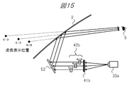
- FIG. 15 is a diagram showing an outline of an example of display distance adjustment using a movable lens in the head-up display device of the present embodiment.
- the image projected from the projector 30a is imaged by a diffusion plate (diffuser) 41b and then incident on the mirror 52 via a movable lens 42b provided in a plurality of areas.
- each movable lens 42b can be individually moved along the optical axis direction by the lens movable portion 282 and the lens movable mechanism 402 shown in FIG.
- the display position of the virtual image based on the image projected from the projector 30a is determined according to the distance between the diffusion plate 41b and each movable lens 42b. Therefore, by moving the movable lens 42b, the focal distance can be changed for each area, and the display distance of the virtual image can be changed.
- the display distance of the corresponding virtual image can be reduced by moving the movable lens 42b to a position close to the diffusion plate 41b as in the uppermost area.
- the display distance of the corresponding virtual image can be increased by moving the movable lens 42b to a position far from the diffusion plate 41b as in the lowermost area.
- the number of movable lenses 42b is not limited to three as illustrated, and can be appropriately configured according to the number of areas.
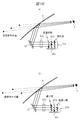
- FIG. 16 is a diagram schematically showing an example of display distance adjustment using the light control mirror 51b in the head-up display device of the present embodiment.
- the dimming mirror 51b is configured by arranging a plurality of dimming mirrors 403 between the LCD 30b and the lens 42a so as to form a matrix when viewed from the cross-sectional direction as illustrated. Then, as shown in FIGS. 16A and 16B, the distance from the LCD 30b to the lens 42a varies from area to area by changing the location of the light control mirror 403 in the mirror state. The display distance of the virtual image can be changed.
- FIG. 17 is a diagram showing an outline of a configuration example of the light control mirror 403.
- the light control mirror 403 is a member such as a film, a sheet, or glass that can control a transmission state and a mirror state by electricity.
- the dimming mirror 403 in the transmissive state transmits the image from the LCD 30b, and only the dimming mirror 403 in the mirror state reflects the image in the direction of the lens 42a.
- dimming is performed so that only one dimming mirror 403 is in a mirror state for each row and each column (each area) for a plurality of dimming mirrors 403 arranged in a matrix when viewed from the cross-sectional direction. It is controlled by the mirror ON / OFF control unit 283.
- only the light control mirror 403 in the lowermost row is set in the mirror state for the area corresponding to the column of the light control mirror 403 closest to the lens 42a. Is set to the transmissive state, the optical path length from the LCD 30b to the lens 42a can be made the shortest, and the display distance of the corresponding virtual image can be made the shortest. Conversely, in the area corresponding to the column of the light control mirror 403 farthest from the lens 42a, only the light control mirror 403 in the uppermost row is set to the mirror state, and the other is set to the transmission state. The optical path length can be made the longest, and the display distance of the corresponding virtual image can be made the longest.
- the length can be made relatively longer than other areas, and the display distance of the corresponding virtual image can be increased.
- the number of the light control mirrors 403 is not limited to 3 rows and 3 columns as shown, and can be appropriately configured according to the number of areas.
- FIG. 18 is a diagram showing an outline of an example of display distance adjustment using a movable diffusion plate in the head-up display device of the present embodiment.
- the image projected from the projector 30a is imaged by a movable diffuser plate (movable diffuser) 41c and then incident on the mirror 52 through the lens 42a.
- the movable diffusion plate 41c can be moved and / or rotated along the optical axis direction by the diffusion plate movable portion 284 and the diffusion plate movable mechanism 404 shown in FIG.
- the display position of the virtual image based on the image projected from the projector 30a is determined according to the distance and / or inclination between the movable diffusion plate 41c and the lens 42a. Therefore, the display distance of the virtual image can be changed by changing the focal length by moving and / or rotating the movable diffusion plate 41c.
- the display distance of the virtual image can be reduced by moving and / or rotating the movable diffusion plate 41c to a position close to the lens 42a. Conversely, the display distance of the virtual image can be increased by moving and / or rotating the movable diffusion plate 41c to a position far from the lens 42a.
- FIG. 19 is a diagram showing an outline of an example of display distance adjustment using the movable optical filter in the head-up display device of the present embodiment.
- a movable optical filter 43a is installed between a lens 42a and a diffuser plate (diffuser) 41b, and as shown in FIGS. 19A and 19B, the movable optical filter 43a is used as an optical path.
- the focal distance for each area the display distance of the virtual image is changed.
- the optical filter is a member having a characteristic of changing a focal length by a single optical component such as a lens or a combination thereof.
- a plurality of optical filters having different refractive indexes are combined to form one optical filter having a different refractive index for each region, and a movable optical filter 43a that can be inserted into and removed from the optical path.
- the movable image filter 43a is inserted into and extracted from the optical path by the optical filter movable unit 285 and the optical filter movable mechanism 405 shown in FIG. The display distance can be changed.
- the focal length of the optical filter corresponding to the lowermost area is minimized,
- the display distance of the virtual image can be shortened, and the focal distance of the optical filter corresponding to the uppermost area can be maximized to shorten the display distance of the virtual image.
- the diffusion plate 41b and the lens 42a are provided for this area.
- the display distance of the virtual image is determined by the distance between and the virtual image display distance can be made farther than the other areas passing through the optical filter.
- the number of regions having different focal lengths in the movable optical filter 43a is not limited to three as shown in the figure, and can be appropriately configured according to the number of areas.
- FIG. 20 is a diagram schematically showing an example of display distance adjustment using a comb-like optical filter in the head-up display device of the present embodiment.
- the image projected from the projector 30a is imaged by a diffusion plate (diffuser) 41b and then incident on the mirror 52 via the comb-like optical filter 43b and the lens 42a.
- the comb-like optical filter 43b is a member provided with a comb-like optical filter portion that has the same function as a lens and can change the display distance of a virtual image according to the focal length.
- the optical filter portion and the portion without the optical filter are associated with each other (not limited to each line but can be set to any line) of the image projected from the projector 30a. By doing so, the display distance of the virtual image can be changed in units of lines.
- the display distance of the virtual image based on the image of the line corresponding to the optical filter portion can be reduced, and the display distance of the virtual image based on the image of the line corresponding to the portion without the optical filter can be increased.
- the head-up display device According to the embodiment of the present invention, even when the virtual image cannot be superimposed on the scenery in front of the vehicle 2 depending on the traveling state of the vehicle 2.
- the AR function can be realized by appropriately superimposing the virtual image on the front landscape. Furthermore, it is possible to appropriately adjust the display distance of the virtual image according to the traveling state or the like.
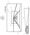
- FIGS. 21A and 21B show a normal display state when the vehicle 2 is traveling on a flat road (see FIG. 21B).
- a navigation display 351 comprising a plurality of guide arrows indicating the traveling direction of the vehicle inside the HUD display area 35 at the substantially central portion thereof. Is superimposed on the road as if looking down from the driver.
- the arrow which is a display object, is displayed with its size changed according to the distance from the vehicle 2, and in this example, the traveling direction is turned left in front of the vehicle.
- symbol 34 in a figure has shown the dashboard.
- FIGS. 22A and 22B show a display state when the vehicle 2 is traveling on the uphill or near the top of the uphill (see, for example, FIG. 22B).
- the navigation display 351 displayed in the HUD display area 35 in the windshield 3 is crushed, which makes it difficult for the driver to see. End up.
- the road in front of the windshield 3 moves out of the HUD display area 35 in the horizontal direction (right side in this example), and the same as above.
- the portion indicating the left turn of the navigation display 351 cannot be displayed.
- FIG. 26 (a) and 26 (b) show measures for solving the problem shown in FIG. 22 in particular.
- a plurality of guide arrows indicating the traveling direction of the vehicle are shown.
- the navigation display 351 is superimposed and displayed on the road as if looking up from the driver.
- FIG. 26A shows a navigation display for a left turn
- FIG. 26B shows a navigation display for a right turn.
- the arrow constituting the navigation display 351 is displayed so that the closer to the vehicle, the closer to the top of the HUD display area 35, and the farther the arrow, the closer to the top of the hill.
- the Rukoto The left turn or right turn corner is displayed so as to be located near the top of the slope.
- FIGS. 27 (a) and (b) show other countermeasures for solving the above-mentioned problems on the uphill and the top of the uphill, and as is clear from these figures, In particular, this is an effective measure when the HUD display area 35 in the windshield 3 is located above the top of the slope, and therefore, navigation display 351 on the road including a corner is impossible. Also in this case, similarly to the above, the navigation display 351 composed of a plurality of guide arrows indicating the traveling direction of the vehicle is superimposed and displayed on the road as if looking up from the driver. Note that FIG. 27A shows a navigation display for a left turn, and FIG. 27B shows a navigation display for a right turn. In this case, the left turn or right turn corner is displayed at the lower end of the HUD display area 35.
- FIGS. 28A and 28B particularly show measures for solving the problem shown in FIG. 23, particularly for left or right turn off the HUD display area 35.
- the corner is displayed using the upper end of the HUD display area 35.
- FIG. 28A shows the navigation display in the case of a left turn
- FIG. 28B shows the navigation display in the case of a right turn.
- the left turn or the right turn is displayed by an arrow having a size corresponding to the distance from the vehicle.
- these corners can be displayed with an arrow 352 having a different form from the arrow 351 indicating straight travel along the road, so that the driver can be emphasized and displayed as supplementary information. It becomes.
- different display forms of the arrow 352 include, for example, different colors or blinking display.
- FIGS. 29A to 29D show measures for solving the problems shown in FIG. 24 in particular. That is, in a situation where the vehicle approaches a curve and the road deviates from the HUD display area 35 in the lateral direction, the arrow 352 having a form different from the arrow 351 indicating the straight traveling along the road is used as described above. By doing this, the left or right turn corner is displayed. In addition, the display of the arrow 352 of a different form is performed in the position of the left or right side edge part of the HUD display area 35.
- FIG. 29A shows a navigation display for a left turn on a right curve
- FIG. 29B shows a navigation display for a right turn on a right curve
- FIG. 29A shows a navigation display for a left turn on a right curve
- FIG. 29B shows a navigation display for a right turn on a right curve
- FIG. 29C shows a left turn on a left curve.
- FIG. 29D shows a navigation display in the case of a right turn on the left curve.
- the color of the arrow 352 can be different from that of the arrow 351 or can be blinked. Will.
- This countermeasure plan is a combination of the plan shown in FIG. 27 (or FIG. 26) and the plan shown in FIG. 29.
- the navigation display 351 composed of the plurality of guide arrows described above is superimposed on the road as seen from the driver, and the arrow 352 having a different form is displayed on the left, right, top, bottom of the HUD display area 35. It is displayed close to the four corners.
- FIG. 30A shows a navigation display for a left turn on a right curve
- FIG. 30B shows a navigation display for a right turn on a right curve
- FIG. 30C shows a left curve.
- FIG. 30D shows the navigation display in the case of a right turn on the left curve.
- FIG. 31 (a) to 31 (d) show proposed measures for the curve near the end of the downhill.
- a navigation display 351 composed of a plurality of guide arrows is displayed superimposed on the road, and a turn or right turn corner that is outside the HUD display area 35 is displayed. Is displayed in close proximity to the left, right, top and bottom corners of the HUD display area 35 using arrows 352 having a different form.
- FIG. 31 (a) shows the navigation display in the case of a left turn in the right curve
- FIG. 31 (b) shows the navigation display in the case of a right turn in the right curve
- FIG. 31 (c) shows the left curve.
- FIG. 31D shows the navigation display in the case of a right turn in the left curve.
- FIG. 32 shows a flowchart as software for that.
- this software is stored in advance in a memory in the control unit 20, for example, and is displayed by the ECU 21 (for example, see FIGS. 3 to 5) in the display image change / determination (S23) process in FIG. Is to be executed.
- a normal HUD operation from the ECU 21 is received (S311), and whether the distance to the corner at which the vehicle turns left or right (referred to as “left and right turn point”) is less than a predetermined threshold value. It is determined whether or not (S312). As a result, in the case of “no”, the process returns to the HUD normal operation of S311 (S313).
- the predetermined threshold is, for example, the distance from the vehicle to the left and right turn points, and is a distance for performing navigation display superimposed on the road, and is set to 100 m as an example. In other words, when the distance to the left and right turn location is 80 m, navigation display of the left and right turn location is performed, and when 120 m, the navigation display is not performed.
- the vertical position of the left and right folding points is within the HUD display area described above. (S314).
- the vertical position of the left and right folding points is the left and right folding points in the HUD display area 35 disposed substantially at the center of the windshield 3 of the vehicle 2 as shown in FIGS. This means the so-called vertical position.
- the countermeasure shown in FIG. 30 (however, the height of the corner is the HUD display area). (S317 is different).
- the countermeasure of FIG. 26 is implemented (S318).
- the result of the determination in S315 is “no”, that is, if the left and right turn points are visible regardless of the convex shape of the road, the left and right turn points are to the left of the HUD display area, as in S316.
- the countermeasure of FIG. 29 is implemented (S320).
- the normal display shown in FIG. 21 is performed (S321).
- the left and right folding points are further at the lower end of the HUD display area. It is determined whether it is below (S322). As a result, when it is determined that “yes”, that is, the left / right folding place is below the HUD display area, it is further determined whether the left / right folding place is to the left or right of the HUD display area. Determination is made (S323). If the result is “yes”, the countermeasure display shown in FIG. 30 is performed (S324). On the other hand, if it is determined as “no”, the normal display shown in FIG. 27 is performed (S325).
- a virtual image corresponding to the traveling state of the vehicle is obtained by changing the form of navigation display (including the horizontal and vertical positions in the HUD display area) according to the road shape.
- a head-up display device capable of displaying an image so as to be appropriately superimposed on an actual landscape.
- the road shape that changes variously in the windshield 3 is obtained from the navigation information shown in FIG.
- Image information from the front of the vehicle is captured from outside the vehicle 116, and further, although not shown, image information from a camera provided toward the front of the vehicle in the vicinity of the driver's eyes (ie, eye point) is captured and image analysis is performed. It is natural for those skilled in the art that it can be realized by such a method.
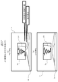
- the eyebox represents the range of viewpoints where the HUD video display can be visually recognized.
- the eyebox is divided into left and right areas individually by the functional liquid crystal film 401 disposed on the upper surface of the dashboard. Control is possible.
- the monocular vision is suitable and the monocular vision is set to the right eye according to the preferred determination
- the right half of the functional liquid crystal film is set in a white state as shown in FIG.
- this eye box is indicated by a broken line 73 at a position immediately before the driver's eyes 5.
- the driver reflects the image light projected from the projector 30a to the mirror 52 through various optical components 41c and 42a, and further to the functional liquid crystal described above.
- the image light of the navigation display reflected through the film 401 and then reflected on the windshield 3 is projected onto the driver's eyes.
- the driver can recognize the navigation display as a virtual image in front of the windshield 3.
- an example in which half of the functional liquid crystal film is in a white state in order to block the image light is shown.
- the liquid crystal film is opaque, and other colors such as gray may be used. Good.
- the size / shape of the eye box 73 is switched by the control of the functional liquid crystal film 401, that is, the right and left Switching between monocular viewing with either eye (see FIG. 34 (a) or (b)) and binocular viewing with both eyes (see FIG. 34 (c)) is controlled (hereinafter referred to as “monocular viewing / both viewing”).
- monocular viewing / both viewing We examined measures to reduce the burden on the driver who would continue to see virtual images displayed in 3D in the HUD display area 35 in front of the windshield 3. .
- FIG. 35 is a flowchart showing the contents of the eyebox control process. First, when the eyebox control process is started, the determination result of the monocular / binocular vision favorableness determination process shown in detail below is captured ( S260).
- the monocular / binocular vision determination process When the monocular / binocular vision determination process is started, first, is the difference between the distance between the real scene (that is, the landscape that can be seen through the windshield) and the virtual image (that is, the navigation display that can be seen through the windshield) greater than or equal to the specified value? It is determined whether or not (S270). As a result, when it is determined as “Yes”, a monocular is suitably set (S271), and the series of processes is terminated. As is clear from the above description, this setting is captured as a determination result of the monocular / binocular vision suitable determination process in the process indicated by S260 in FIG.
- the distance of the actual scene, the inclination of the driver's head, and the brightness of the passenger compartment are the vehicle information acquisition devices shown in FIG. It will be apparent to those skilled in the art that the use of the vehicle interior 115 and the camera 116 (outside the vehicle) can be easily obtained.
- navigation information display that can reduce the burden on the driver even during long-time driving is performed. It is possible to realize a head-up display device capable of
- the software for executing the monocular / binocular control of the navigation information display described above is also stored in advance in, for example, the memory in the control unit 20 constituting the head-up display device according to the present invention, as described above. It is stored and executed by the ECU 21 (see, for example, FIGS. 3 to 5).
- the present invention made by the present inventor has been specifically described based on the embodiments.
- the present invention is not limited to the above-described embodiments, and various modifications can be made without departing from the scope of the invention. Needless to say.
- the above-described embodiment has been described in detail for easy understanding of the present invention, and is not necessarily limited to the one having all the configurations described.
- the present invention can be used for a head-up display device using AR.
- HUD display area 351 ... Navigation display (arrow), 352 ... Arrow of different form, 40 ... Display distance adjustment mechanism, 41a ... Diffusion plate, 41b ... Diffusion plate, 41c ... Movable diffusion plate, 42a ... Lens, 42b ... Movable lens, 43a ... Movable optical filter, 43b ... Comb-like optical filter, 50 ... Mirror drive unit, 51 ... Mirror, 51a ... Mirror, 51b ... Dimming mirror, 52 ... Mirror, 60 ... Speaker, DESCRIPTION OF SYMBOLS 101 ... Vehicle speed sensor, 102 ... Shift position sensor, 103 ... Steering wheel angle sensor, 104 ... Headlight sensor, 105 ... Illuminance sensor, 106 ...
- SYMBOLS 101 ... Vehicle speed sensor, 102 ... Shift position sensor, 103 ... Steering wheel angle sensor, 104 ... Headlight sensor, 105 ... Illuminance sensor, 106 ...
- Chromaticity sensor 107 ... Ranging sensor, 108 ... Infrared sensor, 109 ... Engine start 110, acceleration sensor, 111 ... gyro sensor, 112 ... temperature sensor, 113 ... wireless receiver for road-to-vehicle communication, 114 ... wireless receiver for vehicle-to-vehicle communication, 115 ... camera (inside the vehicle), 116 ... camera (outside the vehicle) 117 ... GPS receiver, 118 ... VICS receiver, 281 ... functional liquid crystal film ON / OFF control unit, 282 ... lens movable unit, 283 ... dimming mirror ON / OFF control unit, 284 ... diffuser plate movable unit, 285 ... optical filter movable unit, 401: Functional liquid crystal film, 402: Lens movable mechanism, 403: Light control mirror, 404: Diffuser movable mechanism, 405: Optical filter movable mechanism.
Landscapes
- Engineering & Computer Science (AREA)
- Physics & Mathematics (AREA)
- General Physics & Mathematics (AREA)
- Mechanical Engineering (AREA)
- Combustion & Propulsion (AREA)
- Transportation (AREA)
- Chemical & Material Sciences (AREA)
- Remote Sensing (AREA)
- Radar, Positioning & Navigation (AREA)
- Optics & Photonics (AREA)
- Automation & Control Theory (AREA)
- Multimedia (AREA)
- Signal Processing (AREA)
- Theoretical Computer Science (AREA)
- Computer Hardware Design (AREA)
- Geometry (AREA)
- Instrument Panels (AREA)
- Testing, Inspecting, Measuring Of Stereoscopic Televisions And Televisions (AREA)
- Controls And Circuits For Display Device (AREA)
Abstract
L'invention concerne un dispositif d'affichage tête haute en mesure de superposer et d'afficher de manière appropriée une image virtuelle sur un paysage réel, en fonction de l'état de déplacement d'un véhicule. Le dispositif d'affichage tête haute de la présente invention comporte : une unité d'acquisition d'informations se rapportant à un véhicule 10 servant à acquérir différents types d'informations se rapportant à un véhicule 4 qu'un véhicule 2 est en mesure de détecter ; une unité de commande 20 servant à commander un affichage d'image en fonction des informations se rapportant au véhicule 4 ; un dispositif d'affichage d'image 30 servant à former une image en fonction d'une instruction en provenance de l'unité de commande 20 ; un miroir 52 servant à faire réfléchir une image formée par le dispositif d'affichage d'image 30 et à la projeter sur un pare-brise 3 ; une unité d'entraînement de miroir 50 servant à changer l'angle du miroir 52 en fonction d'une instruction en provenance de l'unité de commande 20 ; et un mécanisme de réglage de distance d'affichage 40 servant à régler la distance par rapport au conducteur au niveau de laquelle il faut afficher l'image virtuelle. Selon l'invention, en fonction des informations se rapportant au véhicule 4, l'unité de commande 20 ajuste l'angle du miroir 52 en utilisant l'unité d'entraînement de miroir 50, de telle manière qu'il est possible de superposer et d'afficher l'image virtuelle sur le paysage à des fins de visualisation par le conducteur.
Priority Applications (3)
| Application Number | Priority Date | Filing Date | Title |
|---|---|---|---|
| JP2017565393A JP6717856B2 (ja) | 2016-02-05 | 2016-10-20 | ヘッドアップディスプレイ装置 |
| US16/071,518 US10866415B2 (en) | 2016-02-05 | 2016-10-20 | Head-up display apparatus |
| CN201680077971.3A CN108473054B (zh) | 2016-02-05 | 2016-10-20 | 平视显示器装置 |
Applications Claiming Priority (6)
| Application Number | Priority Date | Filing Date | Title |
|---|---|---|---|
| JP2016-020471 | 2016-02-05 | ||
| JP2016020471 | 2016-02-05 | ||
| JP2016-053181 | 2016-03-17 | ||
| JP2016053181 | 2016-03-17 | ||
| JP2016054581 | 2016-03-18 | ||
| JP2016-054581 | 2016-03-18 |
Publications (1)
| Publication Number | Publication Date |
|---|---|
| WO2017134865A1 true WO2017134865A1 (fr) | 2017-08-10 |
Family
ID=59500693
Family Applications (1)
| Application Number | Title | Priority Date | Filing Date |
|---|---|---|---|
| PCT/JP2016/081124 Ceased WO2017134865A1 (fr) | 2016-02-05 | 2016-10-20 | Dispositif d'affichage tête haute |
Country Status (4)
| Country | Link |
|---|---|
| US (1) | US10866415B2 (fr) |
| JP (1) | JP6717856B2 (fr) |
| CN (1) | CN108473054B (fr) |
| WO (1) | WO2017134865A1 (fr) |
Cited By (29)
| Publication number | Priority date | Publication date | Assignee | Title |
|---|---|---|---|---|
| CN108896066A (zh) * | 2018-03-23 | 2018-11-27 | 江苏泽景汽车电子股份有限公司 | 一种增强现实抬头显示器及其导航实现方法 |
| CN108896067A (zh) * | 2018-03-23 | 2018-11-27 | 江苏泽景汽车电子股份有限公司 | 一种用于车载ar导航的动态显示方法及装置 |
| KR20190080749A (ko) * | 2017-12-28 | 2019-07-08 | 도요타지도샤가부시키가이샤 | 차량 탑재 통신 장치 및 차량 |
| EP3264160B1 (fr) * | 2016-03-24 | 2019-08-28 | Panasonic Intellectual Property Management Co., Ltd. | Dispositif d'affichage tête haute, et véhicule |
| JP2019156153A (ja) * | 2018-03-13 | 2019-09-19 | パイオニア株式会社 | 表示制御装置 |
| DE102019107659A1 (de) | 2018-03-30 | 2019-10-02 | Panasonic Intellectual Property Management Co., Ltd. | Anzeigesystem, bewegliches Fahrzeug, Verfahren zur Steuerung des Anzeigesystems und Programm |
| CN110636271A (zh) * | 2018-06-21 | 2019-12-31 | 瑞萨电子株式会社 | 半导体器件和消息图像输出方法 |
| WO2020009217A1 (fr) * | 2018-07-05 | 2020-01-09 | 日本精機株式会社 | Dispositif d'affichage tête haute |
| WO2020009218A1 (fr) * | 2018-07-05 | 2020-01-09 | 日本精機株式会社 | Dispositif d'affichage tête haute |
| WO2020009219A1 (fr) * | 2018-07-05 | 2020-01-09 | 日本精機株式会社 | Dispositif d'affichage tête haute |
| JP2020067460A (ja) * | 2018-10-19 | 2020-04-30 | 本田技研工業株式会社 | 表示装置、表示制御方法、およびプログラム |
| FR3090138A1 (fr) * | 2018-12-17 | 2020-06-19 | Psa Automobiles Sa | Procédé et dispositif de réglage de la luminance d’un afficheur tête haute embarqué dans un véhicule |
| KR20200072641A (ko) * | 2018-12-12 | 2020-06-23 | 삼성전자주식회사 | 3차원 증강 현실을 제공하는 헤드 업 디스플레이 장치 |
| CN111433067A (zh) * | 2017-11-14 | 2020-07-17 | 麦克赛尔株式会社 | 平视显示装置及其显示控制方法 |
| WO2020195625A1 (fr) * | 2019-03-25 | 2020-10-01 | ソニー株式会社 | Dispositif, procédé et programme de traitement d'informations |
| JPWO2020209298A1 (fr) * | 2019-04-11 | 2020-10-15 | ||
| CN111801239A (zh) * | 2018-03-02 | 2020-10-20 | 松下知识产权经营株式会社 | 显示系统 |
| JP2021117220A (ja) * | 2020-01-24 | 2021-08-10 | 株式会社リコー | 表示装置、移動体、表示方法、及びプログラム |
| WO2021175547A1 (fr) * | 2020-03-05 | 2021-09-10 | Daimler Ag | Procédé de présentation de conseils de navigation superposés sur une zone d'image, et système d'assistance d'un véhicule |
| JPWO2021251115A1 (fr) * | 2020-06-08 | 2021-12-16 | ||
| JPWO2021251116A1 (fr) * | 2020-06-08 | 2021-12-16 | ||
| EP3967538A1 (fr) * | 2020-09-09 | 2022-03-16 | Volkswagen Ag | Procédé de représentation d'un élément virtuel |
| JP2022154082A (ja) * | 2021-03-30 | 2022-10-13 | パナソニックIpマネジメント株式会社 | 表示補正システム、表示システム、表示補正方法、及びプログラム |
| JP2022181938A (ja) * | 2021-05-27 | 2022-12-08 | 日本精機株式会社 | ヘッドアップディスプレイ装置 |
| WO2023176897A1 (fr) * | 2022-03-16 | 2023-09-21 | 株式会社小糸製作所 | Dispositif de projection d'images et procédé de projection d'images |
| JP2023136363A (ja) * | 2022-03-16 | 2023-09-29 | 株式会社小糸製作所 | 画像投影装置、および画像投影方法 |
| JP2023137772A (ja) * | 2022-03-18 | 2023-09-29 | 株式会社デンソー | 表示制御装置、及び表示制御プログラム |
| JP2023149942A (ja) * | 2022-03-31 | 2023-10-16 | 株式会社小糸製作所 | 画像投影装置、および画像投影方法 |
| US20240012240A1 (en) * | 2021-01-22 | 2024-01-11 | Bayerische Motoren Werke Aktiengesellschaft | Waveguide-Based Projection Display Device With a Dynamic Scattered Light Absorber for a Vehicle |
Families Citing this family (70)
| Publication number | Priority date | Publication date | Assignee | Title |
|---|---|---|---|---|
| US12112464B2 (en) * | 2014-09-17 | 2024-10-08 | Gary B. Levin | Apparatus and method for onboard stereoscopic inspection of vehicle tires |
| JP6726674B2 (ja) * | 2015-10-15 | 2020-07-22 | マクセル株式会社 | 情報表示装置 |
| US10989929B2 (en) | 2016-02-05 | 2021-04-27 | Maxell, Ltd. | Head-up display apparatus |
| JP6695049B2 (ja) * | 2017-05-10 | 2020-05-20 | パナソニックIpマネジメント株式会社 | 表示装置及び表示制御方法 |
| US11106917B2 (en) * | 2017-07-04 | 2021-08-31 | Turing Video | Surveillance system with human-machine interface |
| US20190012552A1 (en) * | 2017-07-06 | 2019-01-10 | Yves Lambert | Hidden driver monitoring |
| KR20190012068A (ko) * | 2017-07-26 | 2019-02-08 | 삼성전자주식회사 | 전방 표시 장치 및 그 동작 방법 |
| KR102397089B1 (ko) | 2017-07-28 | 2022-05-12 | 삼성전자주식회사 | 이미지 처리 방법 및 이미지 처리 장치 |
| JP6839806B2 (ja) * | 2017-09-21 | 2021-03-10 | パナソニックIpマネジメント株式会社 | ヘッドアップディスプレイ装置、及び車両 |
| KR102547823B1 (ko) * | 2017-12-13 | 2023-06-26 | 삼성전자주식회사 | 컨텐츠 시각화 장치 및 방법 |
| JP6938367B2 (ja) * | 2017-12-28 | 2021-09-22 | アルパイン株式会社 | 車載システム |
| CN108152959B (zh) * | 2018-01-02 | 2020-08-07 | 京东方科技集团股份有限公司 | 车载抬头显示系统 |
| CN108399903B (zh) * | 2018-03-27 | 2020-11-27 | 京东方科技集团股份有限公司 | 一种成像位置的调节方法及装置、平视显示系统 |
| US11719932B2 (en) | 2018-07-13 | 2023-08-08 | Maxell, Ltd. | Head-up display |
| WO2020031915A1 (fr) | 2018-08-06 | 2020-02-13 | 株式会社小糸製作所 | Système d'affichage de véhicule et véhicule |
| EP3835848B1 (fr) * | 2018-08-08 | 2026-03-11 | Panasonic Automotive Systems Co., Ltd. | Affichage " tête haute |
| JP1632766S (fr) * | 2018-09-10 | 2019-06-03 | ||
| US11694369B2 (en) * | 2018-09-21 | 2023-07-04 | Lg Electronics Inc. | Vehicle user interface device and operating method of vehicle user interface device |
| KR102116783B1 (ko) * | 2018-10-10 | 2020-05-29 | 네이버랩스 주식회사 | 영상을 지면에 위치시켜 운전자의 시점에 증강현실을 구현하는 3차원 증강현실 헤드업 디스플레이 |
| KR102673292B1 (ko) * | 2018-10-11 | 2024-06-10 | 현대자동차주식회사 | 차량의 표시 제어 장치 및 방법 |
| KR20200045359A (ko) * | 2018-10-22 | 2020-05-04 | 삼성전자주식회사 | 투시형 디스플레이 장치 |
| CN112956183B (zh) * | 2018-10-31 | 2024-03-12 | 索尼集团公司 | 图像拍摄设备、控制方法和记录程序的介质 |
| CN109584596A (zh) * | 2018-12-20 | 2019-04-05 | 奇瑞汽车股份有限公司 | 车辆驾驶提示方法及装置 |
| US10871693B2 (en) * | 2019-01-02 | 2020-12-22 | Visteon Global Technologies, Inc. | Curved segmented active dimmable lens for a display system |
| KR102648818B1 (ko) * | 2019-01-29 | 2024-03-19 | 현대자동차주식회사 | 차량용 인포테인먼트 장치 및 그의 제어 방법과 그를 포함하는 차량 |
| JP7079747B2 (ja) * | 2019-03-08 | 2022-06-02 | 本田技研工業株式会社 | 表示装置、表示制御方法、およびプログラム |
| CN110161695A (zh) * | 2019-05-17 | 2019-08-23 | 中国科学院光电技术研究所 | 一种成像距离可变的汽车平视显示光学结构 |
| WO2020235160A1 (fr) * | 2019-05-22 | 2020-11-26 | パナソニックIpマネジメント株式会社 | Système d'affichage |
| JP7450230B2 (ja) | 2019-05-29 | 2024-03-15 | パナソニックIpマネジメント株式会社 | 表示システム |
| WO2020241094A1 (fr) * | 2019-05-31 | 2020-12-03 | パナソニックIpマネジメント株式会社 | Système d'affichage |
| DE102019208649B3 (de) * | 2019-06-13 | 2020-01-02 | Volkswagen Aktiengesellschaft | Steuerung einer Anzeige einer Augmented-Reality-Head-up-Display-Vorrichtung für ein Kraftfahrzeug |
| US10908418B1 (en) * | 2019-07-29 | 2021-02-02 | E-Lead Electronic Co., Ltd. | Naked eye 3D head-up display device with reflective diffuser sheet |
| JP7287867B2 (ja) * | 2019-08-30 | 2023-06-06 | トヨタ自動車株式会社 | 車載用制御装置 |
| JP7120982B2 (ja) * | 2019-11-11 | 2022-08-17 | 株式会社Soken | 表示制御装置 |
| KR102862959B1 (ko) * | 2020-01-02 | 2025-09-22 | 삼성전자 주식회사 | 3d 증강 현실 내비게이션 정보 표시 방법 및 장치 |
| CN113109940A (zh) * | 2020-01-10 | 2021-07-13 | 未来(北京)黑科技有限公司 | 一种高亮度的抬头显示系统 |
| CN113103955B (zh) * | 2020-01-10 | 2024-06-18 | 未来(北京)黑科技有限公司 | 一种多层次成像系统 |
| CN113109941B (zh) * | 2020-01-10 | 2023-02-10 | 未来(北京)黑科技有限公司 | 一种分层成像的抬头显示系统 |
| CN113109939B (zh) * | 2020-01-10 | 2023-11-14 | 未来(北京)黑科技有限公司 | 一种多层次成像系统 |
| CN111256704B (zh) * | 2020-01-21 | 2022-06-10 | 华为技术有限公司 | 一种折叠屏的导航方法及相关装置 |
| CN113156643B (zh) * | 2020-01-22 | 2023-08-15 | 未来(北京)黑科技有限公司 | 基于立体视觉显示的车辆显示系统 |
| US12136366B2 (en) * | 2020-02-20 | 2024-11-05 | Sony Group Corporation | Image vibration compensation for vehicle display device |
| JP7130689B2 (ja) * | 2020-03-27 | 2022-09-05 | 矢崎総業株式会社 | 車両用表示装置 |
| JP2021154988A (ja) * | 2020-03-30 | 2021-10-07 | 株式会社豊田中央研究所 | 車載表示装置、車載表示装置を制御する方法、及びコンピュータプログラム |
| GB2593750B (en) | 2020-04-01 | 2024-04-03 | Envisics Ltd | A multi-plane display device |
| CN111442784B (zh) * | 2020-04-03 | 2022-08-02 | 北京四维智联科技有限公司 | 一种基于ar导航的道路引导方法、装置及设备 |
| CN114415370B (zh) * | 2020-05-15 | 2023-06-06 | 华为技术有限公司 | 一种抬头显示装置、显示方法及显示系统 |
| KR102871421B1 (ko) | 2020-08-18 | 2025-10-15 | 삼성전자주식회사 | 컨텐츠를 시각화하는 장치 및 방법 |
| KR20220036455A (ko) * | 2020-09-15 | 2022-03-23 | 현대자동차주식회사 | 증강현실 기반의 주행 정보 표시 장치 |
| CN112255788A (zh) * | 2020-09-29 | 2021-01-22 | 江苏泽景汽车电子股份有限公司 | 一种反射镜不翻转的hud图像调节方法 |
| US11833901B2 (en) * | 2020-10-12 | 2023-12-05 | GM Global Technology Operations LLC | System and method for adjusting a location and distortion of an image projected onto a windshield of a vehicle by a head-up display |
| DE102021101433A1 (de) * | 2021-01-22 | 2022-07-28 | Bayerische Motoren Werke Aktiengesellschaft | Head-Up-Display mit einem Spiegelkabinett zur Bauraumreduktion |
| EP4318077A1 (fr) * | 2021-03-24 | 2024-02-07 | Canon Kabushiki Kaisha | Système optique d'image virtuelle, dispositif d'affichage d'image virtuelle équipé de celui-ci, et système monté sur véhicule |
| KR20220134106A (ko) * | 2021-03-26 | 2022-10-05 | 현대자동차주식회사 | 차량용 헤드업 디스플레이 장치 및 방법 |
| US11922836B2 (en) * | 2021-03-29 | 2024-03-05 | Panasonic Intellectual Property Management Co., Ltd. | Rendering system, display system, display control system, and rendering method |
| JP7767738B2 (ja) * | 2021-06-01 | 2025-11-12 | マツダ株式会社 | ヘッドアップディスプレイ装置 |
| JP7512961B2 (ja) * | 2021-06-23 | 2024-07-09 | トヨタ自動車株式会社 | 表示制御装置、表示方法及び表示プログラム |
| JP7578075B2 (ja) * | 2021-07-07 | 2024-11-06 | トヨタ自動車株式会社 | 車両用表示制御装置、表示方法及びプログラム |
| CN113859122A (zh) * | 2021-09-30 | 2021-12-31 | 重庆长安新能源汽车科技有限公司 | 一种高度自适应调节的ar-hud显示方法、系统和车辆 |
| CN116413908A (zh) * | 2021-12-30 | 2023-07-11 | 未来(北京)黑科技有限公司 | 显示装置、抬头显示器以及交通设备 |
| JPWO2023234076A1 (fr) * | 2022-05-31 | 2023-12-07 | ||
| CN114779477B (zh) * | 2022-06-17 | 2022-11-04 | 江苏泽景汽车电子股份有限公司 | 一种显示画面补偿方法、装置、电子设备及存储介质 |
| JP2024077145A (ja) * | 2022-11-28 | 2024-06-07 | キヤノン株式会社 | 処理装置、処理方法 |
| US20240190245A1 (en) * | 2022-12-07 | 2024-06-13 | Brent Diller | Speed display device |
| TWI879302B (zh) * | 2023-05-11 | 2025-04-01 | 財團法人工業技術研究院 | 抗暈顯示方法、處理裝置與資訊顯示系統 |
| US12555554B2 (en) | 2023-05-11 | 2026-02-17 | Industrial Technology Research Institute | Anti-dizziness display method, processing device, and information display system |
| CN116699852B (zh) * | 2023-06-30 | 2026-03-17 | 沂普光电(福建)有限公司 | 一种hud的参数调整方法、系统和可读存储介质 |
| CN117863873B (zh) * | 2024-01-17 | 2024-11-22 | 江苏泽景汽车电子股份有限公司 | 抬头显示装置、显示控制方法、装置及存储介质 |
| KR20260012307A (ko) * | 2024-07-17 | 2026-01-27 | 삼성디스플레이 주식회사 | 3차원 영상을 표시하는 표시 장치 |
| CN119439511B (zh) * | 2024-11-27 | 2025-09-02 | 江苏泽景汽车电子股份有限公司 | 抬头显示器以及车辆 |
Citations (11)
| Publication number | Priority date | Publication date | Assignee | Title |
|---|---|---|---|---|
| JPH0275330U (fr) * | 1988-11-30 | 1990-06-08 | ||
| JPH04109325U (ja) * | 1991-03-05 | 1992-09-22 | 株式会社カンセイ | 車両用計器 |
| JP2005035384A (ja) * | 2003-07-14 | 2005-02-10 | Nissan Motor Co Ltd | 車両用自動遮光装置 |
| JP2009113710A (ja) * | 2007-11-08 | 2009-05-28 | Denso Corp | ヘッドアップディスプレイ装置 |
| JP2009178404A (ja) * | 2008-01-31 | 2009-08-13 | Carecom Co Ltd | ナースコール子機 |
| JP2011064902A (ja) * | 2009-09-16 | 2011-03-31 | Toshiba Corp | 表示装置及び表示方法 |
| JP2011123126A (ja) * | 2009-12-08 | 2011-06-23 | Denso Corp | ヘッドアップディスプレイ装置及びヘッドアップディスプレイ装置におけるステッピングモータの駆動方法の決定方法 |
| JP2011164631A (ja) * | 2011-03-10 | 2011-08-25 | Toshiba Corp | 表示装置、表示方法及びヘッドアップディスプレイ |
| JP2013237320A (ja) * | 2012-05-14 | 2013-11-28 | Toshiba Alpine Automotive Technology Corp | 違和感軽減表示装置およびその表示制御方法 |
| JP2015080988A (ja) * | 2013-10-22 | 2015-04-27 | 日本精機株式会社 | 車両情報投影システム及び投影装置 |
| JP2015087512A (ja) * | 2013-10-30 | 2015-05-07 | アイシン・エィ・ダブリュ株式会社 | ヘッドアップディスプレイ装置 |
Family Cites Families (35)
| Publication number | Priority date | Publication date | Assignee | Title |
|---|---|---|---|---|
| JPH027533U (fr) | 1988-06-29 | 1990-01-18 | ||
| JPH08197981A (ja) * | 1995-01-23 | 1996-08-06 | Aqueous Res:Kk | 車輌用表示装置 |
| JP2001018682A (ja) * | 1999-07-09 | 2001-01-23 | Calsonic Kansei Corp | 車両用表示装置 |
| JP2004168230A (ja) * | 2002-11-21 | 2004-06-17 | Nissan Motor Co Ltd | 車両用表示装置 |
| DE102004016808A1 (de) * | 2004-04-06 | 2005-10-27 | Robert Bosch Gmbh | Signalisiervorrichtung zur Anzeige von Warn- und/oder Informationshinweisen in Fahrzeugen |
| JP2006007867A (ja) | 2004-06-23 | 2006-01-12 | Matsushita Electric Ind Co Ltd | 車載用映像表示装置 |
| JP2007055365A (ja) | 2005-08-23 | 2007-03-08 | Denso Corp | 車両用表示装置 |
| US8564502B2 (en) * | 2009-04-02 | 2013-10-22 | GM Global Technology Operations LLC | Distortion and perspective correction of vector projection display |
| US8344894B2 (en) * | 2009-04-02 | 2013-01-01 | GM Global Technology Operations LLC | Driver drowsy alert on full-windshield head-up display |
| US8269652B2 (en) * | 2009-04-02 | 2012-09-18 | GM Global Technology Operations LLC | Vehicle-to-vehicle communicator on full-windshield head-up display |
| US8350724B2 (en) * | 2009-04-02 | 2013-01-08 | GM Global Technology Operations LLC | Rear parking assist on full rear-window head-up display |
| US8395529B2 (en) * | 2009-04-02 | 2013-03-12 | GM Global Technology Operations LLC | Traffic infrastructure indicator on head-up display |
| US8912978B2 (en) * | 2009-04-02 | 2014-12-16 | GM Global Technology Operations LLC | Dynamic vehicle system information on full windshield head-up display |
| US8817090B2 (en) * | 2009-04-02 | 2014-08-26 | GM Global Technology Operations LLC | Luminance uniformity compensation of vector projection display |
| US8317329B2 (en) * | 2009-04-02 | 2012-11-27 | GM Global Technology Operations LLC | Infotainment display on full-windshield head-up display |
| US8384531B2 (en) * | 2009-04-02 | 2013-02-26 | GM Global Technology Operations LLC | Recommended following distance on full-windshield head-up display |
| US8830141B2 (en) * | 2009-04-02 | 2014-09-09 | GM Global Technology Operations LLC | Full-windshield head-up display enhancement: anti-reflective glass hard coat |
| US20100253595A1 (en) * | 2009-04-02 | 2010-10-07 | Gm Global Technology Operations, Inc. | Virtual controls and displays by laser projection |
| US8629784B2 (en) * | 2009-04-02 | 2014-01-14 | GM Global Technology Operations LLC | Peripheral salient feature enhancement on full-windshield head-up display |
| US8358224B2 (en) * | 2009-04-02 | 2013-01-22 | GM Global Technology Operations LLC | Point of interest location marking on full windshield head-up display |
| US7924146B2 (en) * | 2009-04-02 | 2011-04-12 | GM Global Technology Operations LLC | Daytime pedestrian detection on full-windscreen head-up display |
| US8072686B2 (en) * | 2009-04-02 | 2011-12-06 | GM Global Technology Operations LLC | UV laser beamlett on full-windshield head-up display |
| US8384532B2 (en) * | 2009-04-02 | 2013-02-26 | GM Global Technology Operations LLC | Lane of travel on windshield head-up display |
| US8704653B2 (en) * | 2009-04-02 | 2014-04-22 | GM Global Technology Operations LLC | Enhanced road vision on full windshield head-up display |
| US8977489B2 (en) * | 2009-05-18 | 2015-03-10 | GM Global Technology Operations LLC | Turn by turn graphical navigation on full windshield head-up display |
| US8164543B2 (en) * | 2009-05-18 | 2012-04-24 | GM Global Technology Operations LLC | Night vision on full windshield head-up display |
| JP2012179935A (ja) * | 2011-02-28 | 2012-09-20 | Jvc Kenwood Corp | 車両用表示装置 |
| WO2014145918A1 (fr) * | 2013-03-15 | 2014-09-18 | Peloton Technology, Inc. | Systèmes et procédés de circulation en peloton de véhicules |
| CN103048786B (zh) * | 2011-10-17 | 2015-07-01 | 财团法人车辆研究测试中心 | 多光路抬头显像装置 |
| JP2014010418A (ja) | 2012-07-03 | 2014-01-20 | Yazaki Corp | 立体表示装置及び立体表示方法 |
| US9445011B2 (en) * | 2012-10-22 | 2016-09-13 | GM Global Technology Operations LLC | Dynamic rearview mirror adaptive dimming overlay through scene brightness estimation |
| WO2015060193A1 (fr) | 2013-10-22 | 2015-04-30 | 日本精機株式会社 | Système de projection d'informations de véhicule, et dispositif de projection |
| JP2015200770A (ja) * | 2014-04-08 | 2015-11-12 | アイシン・エィ・ダブリュ株式会社 | ヘッドアップディスプレイ装置 |
| JP6369106B2 (ja) | 2014-04-16 | 2018-08-08 | 株式会社デンソー | ヘッドアップディスプレイ装置 |
| US10989929B2 (en) * | 2016-02-05 | 2021-04-27 | Maxell, Ltd. | Head-up display apparatus |
-
2016
- 2016-10-20 WO PCT/JP2016/081124 patent/WO2017134865A1/fr not_active Ceased
- 2016-10-20 JP JP2017565393A patent/JP6717856B2/ja active Active
- 2016-10-20 CN CN201680077971.3A patent/CN108473054B/zh active Active
- 2016-10-20 US US16/071,518 patent/US10866415B2/en active Active
Patent Citations (11)
| Publication number | Priority date | Publication date | Assignee | Title |
|---|---|---|---|---|
| JPH0275330U (fr) * | 1988-11-30 | 1990-06-08 | ||
| JPH04109325U (ja) * | 1991-03-05 | 1992-09-22 | 株式会社カンセイ | 車両用計器 |
| JP2005035384A (ja) * | 2003-07-14 | 2005-02-10 | Nissan Motor Co Ltd | 車両用自動遮光装置 |
| JP2009113710A (ja) * | 2007-11-08 | 2009-05-28 | Denso Corp | ヘッドアップディスプレイ装置 |
| JP2009178404A (ja) * | 2008-01-31 | 2009-08-13 | Carecom Co Ltd | ナースコール子機 |
| JP2011064902A (ja) * | 2009-09-16 | 2011-03-31 | Toshiba Corp | 表示装置及び表示方法 |
| JP2011123126A (ja) * | 2009-12-08 | 2011-06-23 | Denso Corp | ヘッドアップディスプレイ装置及びヘッドアップディスプレイ装置におけるステッピングモータの駆動方法の決定方法 |
| JP2011164631A (ja) * | 2011-03-10 | 2011-08-25 | Toshiba Corp | 表示装置、表示方法及びヘッドアップディスプレイ |
| JP2013237320A (ja) * | 2012-05-14 | 2013-11-28 | Toshiba Alpine Automotive Technology Corp | 違和感軽減表示装置およびその表示制御方法 |
| JP2015080988A (ja) * | 2013-10-22 | 2015-04-27 | 日本精機株式会社 | 車両情報投影システム及び投影装置 |
| JP2015087512A (ja) * | 2013-10-30 | 2015-05-07 | アイシン・エィ・ダブリュ株式会社 | ヘッドアップディスプレイ装置 |
Cited By (56)
| Publication number | Priority date | Publication date | Assignee | Title |
|---|---|---|---|---|
| EP3264160B1 (fr) * | 2016-03-24 | 2019-08-28 | Panasonic Intellectual Property Management Co., Ltd. | Dispositif d'affichage tête haute, et véhicule |
| CN111433067A (zh) * | 2017-11-14 | 2020-07-17 | 麦克赛尔株式会社 | 平视显示装置及其显示控制方法 |
| KR102227103B1 (ko) | 2017-12-28 | 2021-03-12 | 도요타지도샤가부시키가이샤 | 차량 탑재 통신 장치 및 차량 |
| KR20190080749A (ko) * | 2017-12-28 | 2019-07-08 | 도요타지도샤가부시키가이샤 | 차량 탑재 통신 장치 및 차량 |
| CN111801239A (zh) * | 2018-03-02 | 2020-10-20 | 松下知识产权经营株式会社 | 显示系统 |
| JP2019156153A (ja) * | 2018-03-13 | 2019-09-19 | パイオニア株式会社 | 表示制御装置 |
| JP2024180496A (ja) * | 2018-03-13 | 2024-12-26 | パイオニア株式会社 | 表示制御装置 |
| CN108896066A (zh) * | 2018-03-23 | 2018-11-27 | 江苏泽景汽车电子股份有限公司 | 一种增强现实抬头显示器及其导航实现方法 |
| CN108896067A (zh) * | 2018-03-23 | 2018-11-27 | 江苏泽景汽车电子股份有限公司 | 一种用于车载ar导航的动态显示方法及装置 |
| CN108896067B (zh) * | 2018-03-23 | 2022-09-30 | 江苏泽景汽车电子股份有限公司 | 一种用于车载ar导航的动态显示方法及装置 |
| DE102019107659A1 (de) | 2018-03-30 | 2019-10-02 | Panasonic Intellectual Property Management Co., Ltd. | Anzeigesystem, bewegliches Fahrzeug, Verfahren zur Steuerung des Anzeigesystems und Programm |
| DE102019107659B4 (de) | 2018-03-30 | 2022-06-15 | Panasonic Intellectual Property Management Co., Ltd. | Anzeigesystem, bewegliches Fahrzeug, Verfahren zur Steuerung des Anzeigesystems und Programm |
| US10983343B2 (en) | 2018-03-30 | 2021-04-20 | Panasonic Intellectual Property Management Co., Ltd. | Display system, moving vehicle, method for controlling the display system, and non-transitory storage medium |
| CN110636271A (zh) * | 2018-06-21 | 2019-12-31 | 瑞萨电子株式会社 | 半导体器件和消息图像输出方法 |
| CN110636271B (zh) * | 2018-06-21 | 2022-09-09 | 瑞萨电子株式会社 | 半导体器件和消息图像输出方法 |
| JP7310817B2 (ja) | 2018-07-05 | 2023-07-19 | 日本精機株式会社 | ヘッドアップディスプレイ装置 |
| US11370304B2 (en) | 2018-07-05 | 2022-06-28 | Nippon Seiki Co., Ltd. | Head-up display device |
| JP7338625B2 (ja) | 2018-07-05 | 2023-09-05 | 日本精機株式会社 | ヘッドアップディスプレイ装置 |
| JP7375753B2 (ja) | 2018-07-05 | 2023-11-08 | 日本精機株式会社 | ヘッドアップディスプレイ装置 |
| WO2020009219A1 (fr) * | 2018-07-05 | 2020-01-09 | 日本精機株式会社 | Dispositif d'affichage tête haute |
| WO2020009218A1 (fr) * | 2018-07-05 | 2020-01-09 | 日本精機株式会社 | Dispositif d'affichage tête haute |
| JPWO2020009217A1 (ja) * | 2018-07-05 | 2021-08-02 | 日本精機株式会社 | ヘッドアップディスプレイ装置 |
| WO2020009217A1 (fr) * | 2018-07-05 | 2020-01-09 | 日本精機株式会社 | Dispositif d'affichage tête haute |
| JPWO2020009218A1 (ja) * | 2018-07-05 | 2021-08-12 | 日本精機株式会社 | ヘッドアップディスプレイ装置 |
| JPWO2020009219A1 (ja) * | 2018-07-05 | 2021-08-12 | 日本精機株式会社 | ヘッドアップディスプレイ装置 |
| US10928632B2 (en) | 2018-10-19 | 2021-02-23 | Honda Motor Co., Ltd. | Display device, display control method, and storage medium |
| JP2020067460A (ja) * | 2018-10-19 | 2020-04-30 | 本田技研工業株式会社 | 表示装置、表示制御方法、およびプログラム |
| KR102766549B1 (ko) * | 2018-12-12 | 2025-02-12 | 삼성전자주식회사 | 3차원 증강 현실을 제공하는 헤드 업 디스플레이 장치 |
| KR20200072641A (ko) * | 2018-12-12 | 2020-06-23 | 삼성전자주식회사 | 3차원 증강 현실을 제공하는 헤드 업 디스플레이 장치 |
| FR3090138A1 (fr) * | 2018-12-17 | 2020-06-19 | Psa Automobiles Sa | Procédé et dispositif de réglage de la luminance d’un afficheur tête haute embarqué dans un véhicule |
| US12552317B2 (en) | 2019-03-25 | 2026-02-17 | Sony Group Corporation | Information processing device and information processing method |
| WO2020195625A1 (fr) * | 2019-03-25 | 2020-10-01 | ソニー株式会社 | Dispositif, procédé et programme de traitement d'informations |
| JPWO2020209298A1 (fr) * | 2019-04-11 | 2020-10-15 | ||
| WO2020209298A1 (fr) * | 2019-04-11 | 2020-10-15 | パナソニックIpマネジメント株式会社 | Système de détection de changement de gradient, système d'affichage l'utilisant, et programme pour le déplacement d'un corps |
| US12223861B2 (en) | 2019-04-11 | 2025-02-11 | Panasonic Intellectual Property Management Co., Ltd. | Gradient change detection system, display system using same, and storage medium that stores program for moving body |
| JP7507439B2 (ja) | 2019-04-11 | 2024-06-28 | パナソニックIpマネジメント株式会社 | 勾配変化検出システム、それを用いた表示システム及び移動体用プログラム |
| JP2021117220A (ja) * | 2020-01-24 | 2021-08-10 | 株式会社リコー | 表示装置、移動体、表示方法、及びプログラム |
| JP7585754B2 (ja) | 2020-01-24 | 2024-11-19 | 株式会社リコー | 表示装置、移動体、表示方法、及びプログラム |
| WO2021175547A1 (fr) * | 2020-03-05 | 2021-09-10 | Daimler Ag | Procédé de présentation de conseils de navigation superposés sur une zone d'image, et système d'assistance d'un véhicule |
| WO2021251116A1 (fr) * | 2020-06-08 | 2021-12-16 | パナソニックIpマネジメント株式会社 | Système d'affichage |
| US12194851B2 (en) | 2020-06-08 | 2025-01-14 | Panasonic Intellectual Property Management Co., Ltd. | Display system |
| JPWO2021251115A1 (fr) * | 2020-06-08 | 2021-12-16 | ||
| JPWO2021251116A1 (fr) * | 2020-06-08 | 2021-12-16 | ||
| JP7617532B2 (ja) | 2020-06-08 | 2025-01-20 | パナソニックIpマネジメント株式会社 | 表示システム |
| EP3967538A1 (fr) * | 2020-09-09 | 2022-03-16 | Volkswagen Ag | Procédé de représentation d'un élément virtuel |
| US20240012240A1 (en) * | 2021-01-22 | 2024-01-11 | Bayerische Motoren Werke Aktiengesellschaft | Waveguide-Based Projection Display Device With a Dynamic Scattered Light Absorber for a Vehicle |
| JP7555662B2 (ja) | 2021-03-30 | 2024-09-25 | パナソニックオートモーティブシステムズ株式会社 | 表示補正システム、表示システム、表示補正方法、及びプログラム |
| JP2022154082A (ja) * | 2021-03-30 | 2022-10-13 | パナソニックIpマネジメント株式会社 | 表示補正システム、表示システム、表示補正方法、及びプログラム |
| JP7661790B2 (ja) | 2021-05-27 | 2025-04-15 | 日本精機株式会社 | ヘッドアップディスプレイ装置 |
| JP2022181938A (ja) * | 2021-05-27 | 2022-12-08 | 日本精機株式会社 | ヘッドアップディスプレイ装置 |
| WO2023176897A1 (fr) * | 2022-03-16 | 2023-09-21 | 株式会社小糸製作所 | Dispositif de projection d'images et procédé de projection d'images |
| JP2023136363A (ja) * | 2022-03-16 | 2023-09-29 | 株式会社小糸製作所 | 画像投影装置、および画像投影方法 |
| JP7769569B2 (ja) | 2022-03-16 | 2025-11-13 | 株式会社小糸製作所 | 画像投影装置、および画像投影方法 |
| JP2023137772A (ja) * | 2022-03-18 | 2023-09-29 | 株式会社デンソー | 表示制御装置、及び表示制御プログラム |
| JP7790226B2 (ja) | 2022-03-18 | 2025-12-23 | 株式会社デンソー | 表示制御装置、及び表示制御プログラム |
| JP2023149942A (ja) * | 2022-03-31 | 2023-10-16 | 株式会社小糸製作所 | 画像投影装置、および画像投影方法 |
Also Published As
| Publication number | Publication date |
|---|---|
| JP6717856B2 (ja) | 2020-07-08 |
| CN108473054B (zh) | 2021-05-28 |
| CN108473054A (zh) | 2018-08-31 |
| JPWO2017134865A1 (ja) | 2018-12-20 |
| US10866415B2 (en) | 2020-12-15 |
| US20190025580A1 (en) | 2019-01-24 |
Similar Documents
| Publication | Publication Date | Title |
|---|---|---|
| JP6717856B2 (ja) | ヘッドアップディスプレイ装置 | |
| CN108473055B (zh) | 平视显示器装置 | |
| JP6588167B2 (ja) | ヘッドアップディスプレイ装置 | |
| JP6707666B2 (ja) | ヘッドアップディスプレイ装置 | |
| JP6138634B2 (ja) | ヘッドアップディスプレイ装置 | |
| US10250860B2 (en) | Electronic apparatus and image display method | |
| CN112292630A (zh) | 用于运行用于机动车的视野显示设备的方法 | |
| US10302953B2 (en) | Adjustable head-up display arrangement for a vehicle | |
| WO2014208165A1 (fr) | Dispositif d'affichage tête haute | |
| JP6213323B2 (ja) | ヘッドアップディスプレイ装置 | |
| JP2016109645A (ja) | 情報提供装置、情報提供方法及び情報提供用制御プログラム | |
| JP6876277B2 (ja) | 制御装置、表示装置、表示方法及びプログラム | |
| WO2018167844A1 (fr) | Dispositif d'affichage tête haute et procédé d'affichage d'image de celui-ci | |
| JP7082745B2 (ja) | 車両用表示装置 | |
| JPWO2019130860A1 (ja) | ヘッドアップディスプレイ装置、および制御プログラム | |
| JP6196840B2 (ja) | ヘッドアップディスプレイ装置 | |
| JP6102628B2 (ja) | ヘッドアップディスプレイ装置 | |
| WO2020049873A1 (fr) | Dispositif d'affichage tête haute |
Legal Events
| Date | Code | Title | Description |
|---|---|---|---|
| 121 | Ep: the epo has been informed by wipo that ep was designated in this application |
Ref document number: 16889348 Country of ref document: EP Kind code of ref document: A1 |
|
| WWE | Wipo information: entry into national phase |
Ref document number: 2017565393 Country of ref document: JP |
|
| NENP | Non-entry into the national phase |
Ref country code: DE |
|
| 122 | Ep: pct application non-entry in european phase |
Ref document number: 16889348 Country of ref document: EP Kind code of ref document: A1 |