WO2017135017A1 - Dispositif de visualisation pour véhicule - Google Patents
Dispositif de visualisation pour véhicule Download PDFInfo
- Publication number
- WO2017135017A1 WO2017135017A1 PCT/JP2017/001137 JP2017001137W WO2017135017A1 WO 2017135017 A1 WO2017135017 A1 WO 2017135017A1 JP 2017001137 W JP2017001137 W JP 2017001137W WO 2017135017 A1 WO2017135017 A1 WO 2017135017A1
- Authority
- WO
- WIPO (PCT)
- Prior art keywords
- coil spring
- gear
- clutch plate
- plate
- rotating member
- Prior art date
- Legal status (The legal status is an assumption and is not a legal conclusion. Google has not performed a legal analysis and makes no representation as to the accuracy of the status listed.)
- Ceased
Links
Images



Classifications
-
- B—PERFORMING OPERATIONS; TRANSPORTING
- B60—VEHICLES IN GENERAL
- B60R—VEHICLES, VEHICLE FITTINGS, OR VEHICLE PARTS, NOT OTHERWISE PROVIDED FOR
- B60R1/00—Optical viewing arrangements; Real-time viewing arrangements for drivers or passengers using optical image capturing systems, e.g. cameras or video systems specially adapted for use in or on vehicles
- B60R1/02—Rear-view mirror arrangements
- B60R1/06—Rear-view mirror arrangements mounted on vehicle exterior
- B60R1/062—Rear-view mirror arrangements mounted on vehicle exterior with remote control for adjusting position
- B60R1/07—Rear-view mirror arrangements mounted on vehicle exterior with remote control for adjusting position by electrically powered actuators
-
- B—PERFORMING OPERATIONS; TRANSPORTING
- B60—VEHICLES IN GENERAL
- B60R—VEHICLES, VEHICLE FITTINGS, OR VEHICLE PARTS, NOT OTHERWISE PROVIDED FOR
- B60R1/00—Optical viewing arrangements; Real-time viewing arrangements for drivers or passengers using optical image capturing systems, e.g. cameras or video systems specially adapted for use in or on vehicles
- B60R1/02—Rear-view mirror arrangements
- B60R1/06—Rear-view mirror arrangements mounted on vehicle exterior
- B60R1/062—Rear-view mirror arrangements mounted on vehicle exterior with remote control for adjusting position
- B60R1/07—Rear-view mirror arrangements mounted on vehicle exterior with remote control for adjusting position by electrically powered actuators
- B60R1/074—Rear-view mirror arrangements mounted on vehicle exterior with remote control for adjusting position by electrically powered actuators for retracting the mirror arrangements to a non-use position alongside the vehicle
Definitions
- the present invention relates to a vehicle visual recognition device in which visual recognition means assists visual recognition of a vehicle occupant.
- the coil spring biases the clutch toward the main gear, and the clutch restricts the rotation of the main gear, so that a driving force is applied from the motor to the main gear. As a result, the mirror is rotated.
- An object of the present invention is to obtain a vehicular visual recognition device that can prevent the biasing means from being deformed in the rotation direction of the rotating member even when a driving force is applied to the rotating member in consideration of the above facts.
- the visual device for a vehicle includes a rotating member that is rotatably provided, a restricting member that restricts rotation of the rotating member, and assists the vehicle occupant in visually recognizing the driving force applied to the rotating member. And a urging means for applying a urging force in the rotating direction of the rotating member to one of the rotating member and the restricting member.
- the vehicular visual recognition device is the vehicle visual recognition device according to the first aspect of the present invention, in which the urging means applies an urging force to the restriction member.
- the vehicular visual recognition device is the vehicle visual recognition device according to the first or second aspect of the present invention, wherein the urging means is attached to one of the rotating member and the limiting member from the longitudinal end surface. Apply power.
- the visual device for a vehicle according to a fourth aspect of the present invention is the visual device for a vehicle according to any one of the first to third aspects of the present invention, and is provided on one of the rotating member and the restricting member.
- a contact surface is provided in which a contact area of the biasing means to one of the rotating member and the restricting member is increased by contacting and tilting the biasing means.
- the restricting member restricts the rotation of the rotating member, and the visual recognition means assists visual recognition of the vehicle occupant. Further, when the driving force is applied to the rotating member, the visual recognition means is rotated.
- the biasing means applies a biasing force in the rotation direction of the rotating member to one of the rotating member and the limiting member. For this reason, even when a driving force is applied to the rotating member, the biasing means can be prevented from being deformed in the rotating direction of the rotating member via the rotating member.
- the urging means applies an urging force to the restricting member. For this reason, it can suppress that a rotation member is moved when the rotation limitation of the rotation member by a limitation member is cancelled
- the urging means applies an urging force to one of the rotating member and the limiting member from the longitudinal end surface. For this reason, the biasing means can effectively exert a biasing force on one of the rotating member and the limiting member.
- the contact surface is provided on one of the rotation member and the limiting member, the urging means is in contact with the contact surface, and the contact surface is inclined to rotate.
- the contact area of the biasing means to one of the member and the limiting member is increased. For this reason, the area
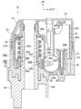
- FIG. 4 is a cross-sectional view (a cross-sectional view taken along line 4-4 in FIG. 2) showing the storage mechanism in the vehicle door mirror device according to the embodiment of the present invention. It is a disassembled perspective view which shows the coil spring and clutch plate of the storage mechanism in the door mirror apparatus for vehicles which concerns on embodiment of this invention.
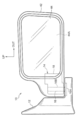
- FIG. 1 is a front view of a vehicle door mirror device 10 as a vehicle visual recognition device according to an embodiment of the present invention as viewed from the rear of the vehicle.
- the front side of the vehicle is indicated by an arrow FR
- the outer side in the vehicle width direction (right side of the vehicle)
- the upper side is indicated by an arrow UP.
- the vehicle door mirror device 10 is provided at the middle in the vertical direction of the side door (particularly the front side door) as the vehicle door and at the front end of the vehicle, and is disposed outside the vehicle.
- the vehicle door mirror device 10 includes a stay 12 as an installation member.
- the vehicle door mirror device 10 is fixed to the side door (vehicle body side) of the stay 12 in the vehicle width direction. 10 is installed in the side door.
- a storage mechanism 14 (electric storage mechanism, retractor) as a rotation mechanism is supported on the upper side of the vehicle width direction outer portion of the stay 12.
- the storage mechanism 14 is provided with a metal stand 16 as a support.
- a substantially disc-shaped fixing portion 16A is provided at the lower end of the stand 16, and the fixing portion 16A is fixed to the stay 12, so that the stand 16 is fixed to the stay 12 and the storage mechanism 14 is fixed to the stay 12. It is supported by.
- a substantially cylindrical support shaft 16B is integrally provided on the upper side of the fixed portion 16A, and the axial direction of the support shaft 16B is arranged vertically.
- a predetermined number (four in the present embodiment) of insertion grooves 16C having a substantially rectangular cross section as a locking portion are formed on the outer peripheral surface of the support shaft 16B.
- the predetermined number of insertion grooves 16C is formed on the support shaft 16B. They are arranged at equal intervals in the circumferential direction.
- the insertion groove 16C extends in the axial direction of the support shaft 16B, and the insertion groove 16C is opened upward.
- Rotating body 18 is rotatably supported on support shaft 16B.
- the lower portion of the rotating body 18 is provided with a resin-made case 20 as a rotating member, and the upper surface of the case 20 is open.
- a support shaft 16B of the stand 16 is penetrated and fitted into the inner portion of the lower wall of the case 20 in the vehicle width direction, and the case 20 is rotatably supported by the support shaft 16B.
- a resin motor base 22 as an assembly member is fixed.
- a substantially cylindrical housing cylinder 22A is provided on the inner side in the vehicle width direction of the motor base 22, and a support shaft 16B of the stand 16 is coaxially housed in the housing cylinder 22A.
- a substantially rectangular plate-like bottom wall 22B is provided on the outer side of the motor base 22 in the vehicle width direction, and the bottom wall 22B is integrated with the lower end of the housing cylinder 22A.
- a substantially oval cylindrical assembly cylinder 22C is integrally provided on the upper surface of the bottom wall 22B, and the assembly cylinder 22C projects upward from the bottom wall 22B.
- the upper side of the case 20 and the motor base 22 is provided with a resin-made cover 24 as a covering member, and the lower surface of the cover 24 is open.
- the lower end of the cover 24 is fixed to the outer periphery of the upper end portion of the case 20, and the cover 24 covers the upper side of the case 20 and the motor base 22.
- a motor 26 as a driving means is provided in the rotating body 18.
- the motor 26 is provided with a substantially elliptical columnar main body portion 26 ⁇ / b> A, and the main body portion 26 ⁇ / b> A is assembled and fixed from above in the assembly cylinder 22 ⁇ / b> C of the motor base 22.
- a metal output shaft 26B (motor shaft) extends coaxially from the main body 26A.
- the axial direction of the output shaft 26 ⁇ / b> B is arranged vertically, and the output shaft 26 ⁇ / b> B extends through the bottom wall 22 ⁇ / b> B of the motor base 22 and extends below the motor base 22.
- the storage mechanism 14 is operated by driving the motor 26 and rotating the output shaft 26B.
- a gear mechanism 28 is provided.
- the gear mechanism 28 is provided with a resin worm gear 30 as a first stage gear on the lower side of the motor 26.
- the worm gear 30 is arranged in the vertical direction in the axial direction, and the lower part is the lower wall of the case 20. Is supported rotatably.
- the output shaft 26B of the motor 26 is coaxially inserted into the worm gear 30 from above, and the worm gear 30 is rotated integrally with the output shaft 26B by rotating the output shaft 26B.
- the gear mechanism 28 is provided with a worm shaft 32 as an intermediate gear on the inner side in the vehicle width direction of the worm gear 30.
- the worm shaft 32 is arranged in the horizontal direction in the axial direction, and is arranged on the lower wall of the case 20. It is supported rotatably.
- a helical gear portion 32A made of resin is coaxially provided at one end portion (vehicle rear portion) of the worm shaft 32, and a worm is provided at the other end portion (vehicle front portion) of the worm shaft 32.
- the metal worm gear portion 32B is provided coaxially.
- the helical gear portion 32A is meshed with the worm gear 30. When the worm gear 30 is rotated, the helical gear portion 32A and the worm gear portion 32B are integrally rotated, and the worm shaft 32 is rotated.
- the gear mechanism 28 is provided with a metal gear plate 34 (worm wheel) as a rotating member (final gear) on the inner side in the vehicle width direction of the worm shaft 32.
- a support shaft 16B of the stand 16 is coaxially penetrated through the gear plate 34, and the gear plate 34 is rotatably supported by the support shaft 16B and supported by the lower wall of the case 20 from below. Yes.
- a concave portion 34A having a circular shape in plan view is formed on the upper surface of the gear plate 34 on the same axis, and the concave portion 34A is open to the upper side.
- a predetermined number (5 in this embodiment) of moderation recesses 34B as engaged portions are formed on the lower surface of the recess 34A, and the predetermined number of moderation recesses 34B are equally spaced in the circumferential direction of the gear plate 34.
- the moderation recess 34B has an inverted trapezoidal cross section, and both side surfaces of the moderation recess 34B are inclined in an upward direction toward the outer side in the circumferential direction of the gear plate 34 of the moderation recess 34B.
- a substantially cylindrical clutch plate 36 (see FIG. 5) made of metal as a limiting member is provided on the upper side of the gear plate 34.
- the support shaft 16B of the stand 16 is coaxially penetrated through the clutch plate 36, and the clutch plate 36 is fitted into the recess 34A of the gear plate 34.
- a predetermined number (four in this embodiment) of substantially rectangular columnar insertion protrusions 36 ⁇ / b> A serving as locked portions are formed on the inner peripheral surface of the clutch plate 36, and the predetermined number of insertion protrusions 36 ⁇ / b> A includes the clutch plate 36.
- the insertion protrusion 36A is inserted into the insertion groove 16C of the support shaft 16B (substantially fitted in the circumferential direction of the support shaft 16B and the clutch plate 36), and the clutch plate 36 is locked from rotating with respect to the support shaft 16B.
- the support shaft 16B is movable in the vertical direction.
- a predetermined number (5 in this embodiment) of moderation convex portions 36B as engaging portions are formed on the lower surface of the clutch plate 36, and the predetermined number of moderation convex portions 36B are equal in the circumferential direction of the clutch plate 36, etc. Arranged at intervals.
- the moderation convex portion 36B has an inverted trapezoidal cross section, and both side surfaces of the moderation convex portion 36B are inclined in a downward direction as it goes inward in the circumferential direction of the clutch plate 36 of the moderation convex portion 36B.
- the cross-sectional shape of the moderation convex portion 36B is slightly smaller than the cross-sectional shape of the moderation concave portion 34B of the gear plate 34, and the moderation convex portion 36B is inserted into the moderation concave portion 34B (the gear plate 34 and the clutch plate 36).
- the lower surface of the clutch plate 36 is brought into contact (locked) with the lower surface of the recess 34A of the gear plate 34.
- a contact surface 36C is formed on the upper surface of the clutch plate 36, and the contact surface 36C is inclined downward in the backward direction (the direction of arrow A in FIG. 5 and the like).
- a planar urging surface 36D is formed between the rearward direction side end of the contact surface 36C and the forward end direction (the direction of arrow B in FIG. 5).
- the biasing surface 36 ⁇ / b> D is disposed perpendicular to the circumferential direction of the clutch plate 36.
- a coil spring 38 (see FIG. 5) made of metal as a biasing means and having a spiral rod shape and a circular cross section is provided.
- the coil spring 38 has a support shaft 16B of the stand 16 inside. Is inserted on the same axis, and is extended downward in the backward direction. The lower end of the coil spring 38 is in contact with the contact surface 36C of the clutch plate 36, and the lower end surface in the longitudinal direction of the coil spring 38 is flattened to contact (lock) the biasing surface 36D of the clutch plate 36.
- a substantially annular plate-like push nut 40 as a locking member is provided on the upper side of the coil spring 38, and the push nut 40 is coaxially fixed to the support shaft 16 ⁇ / b> B of the stand 16.
- the push nut 40 presses the coil spring 38 downward and compresses it in the axial direction.
- the lower end of the coil spring 38 urges the contact surface 36C of the clutch plate 36 downward, and the coil spring 38 is engaged with the clutch.
- the plate 36 is biased downward. Therefore, the coil spring 38 is engaged with the clutch plate 36 by the gear plate 34 by the downward biasing force, and the moderation convex portion 36B of the clutch plate 36 is inserted into the moderation concave portion 34B of the gear plate 34.
- the rotation of the gear plate 34 is restricted by the clutch plate 36.
- the push nut 40 presses the upper end surface in the longitudinal direction of the coil spring 38 in the backward direction, and elastically expands the coil spring 38, and the lower end surface in the longitudinal direction of the coil spring 38 biases the clutch plate 36.
- the surface 36D is biased toward the backward direction, and the coil spring 38 biases the clutch plate 36 toward the backward direction.
- the coil spring 38 abuts the side face of the moderation convex portion 36B of the clutch plate 36 against the side face of the reverse direction of the moderation concave portion 34B of the gear plate 34 by the urging force in the backward direction.
- the rearward direction side surface of the insertion protrusion 36A of the clutch plate 36 is brought into contact with the rearward direction side surface of the insertion groove 16C of the stand 16 (support shaft 16B).
- the gear plate 34 meshes with the worm gear portion 32B of the worm shaft 32, whereby the rotation of the worm gear portion 32B around the gear plate 34 is locked, and the rotation of the rotating body 18 with respect to the gear plate 34 is prevented. It is locked. As described above, when the worm gear portion 32B is rotated, the worm gear portion 32B is rotated around the gear plate 34, whereby the rotating body 18 is rotated with respect to the gear plate 34 integrally with the worm gear portion 32B.
- the rotating body 18 is accommodated in a vehicle width direction inside portion of a substantially rectangular parallelepiped container-like visor 42 as an accommodating member, and the vehicle rear side surface of the visor 42 is open.
- a substantially rectangular plate-like mirror 44 is disposed as a visual recognition means in the vicinity of the vehicle rear side surface (open portion).
- the visor 42 covers the entire circumference of the mirror 44 and the vehicle front side surface. Yes.
- the visor 42 and the mirror 44 are connected to and supported by the rotating body 18, and the visor 42 and the mirror 44 project together with the rotating body 18 outward in the vehicle width direction with respect to the side door, and are raised (deployed). ing.
- the mirror surface 44A of the mirror 44 is directed to the rear side of the vehicle, whereby the mirror 44 enables the vehicle occupant (especially the driver) to visually recognize the vehicle rear side and assists the occupant's visual recognition.
- the visor 42 and the mirror 44 are rotatable around the support shaft 16 ⁇ / b> B of the stand 16 together with the rotating body 18.
- the coil spring 38 engages the clutch plate 36 with the gear plate 34 by the downward biasing force (the moderation convex portion 36B of the clutch plate 36 is The state where the gear plate 34 is inserted into the moderation recess 34B of the gear plate 34 is maintained), the gear plate 34 with respect to the clutch plate 36 in the backward direction (the direction of arrow A in FIG. 4) and the forward direction (the arrow in FIG. 4).
- Rotation in the direction B) is limited, and rotation in the backward direction (rear storage direction) and forward direction (front storage direction) of the rotating body 18, the visor 42, and the mirror 44 is limited.
- the output shaft 26B is rotated by driving the motor 26. Therefore, in the gear mechanism 28, the worm gear 30 is rotated integrally with the output shaft 26B, and the worm shaft 32 (helical gear portion 32A and worm gear portion 32B) is rotated, so that the worm gear portion 32B rotates around the gear plate 34.
- the rotating body 18, the visor 42, and the mirror 44 are rotated with respect to the gear plate 34 integrally with the worm gear portion 32B.
- the worm gear portion 32B is rotated backward around the gear plate 34, so that the rotating body 18, the visor 42 and the mirror 44 are rotated. It is rotated in the backward direction (the vehicle rear side and the vehicle width direction inner side). Thereby, the rotation body 18, the visor 42, and the mirror 44 are released from the side door and stored (rearly stored).
- the coil spring 38 urges the clutch plate 36 in the backward direction, and the side face of the moderation convex portion 36B of the clutch plate 36 abuts the side face of the moderation concave portion 34B of the gear plate 34 in the backward direction.
- the rearward side surface of the insertion protrusion 36A of the clutch plate 36 is brought into contact with the rearward side surface of the insertion groove 16C of the stand 16 (support shaft 16B).
- the coil spring 38 biases the clutch plate 36 in the backward direction.
- the coil spring 38 applies a biasing force in the backward direction to the clutch plate 36. Therefore, the engagement of the clutch plate 36 with the gear plate 34 is released (the insertion of the moderation convex portion 36B into the moderation concave portion 34B is released), and the rotation restriction of the gear plate 34 by the clutch plate 36 is released. At this time, the clutch plate 36 can move upward with respect to the gear plate 34. Thus, unlike the case where the coil spring 38 applies a biasing force in the backward direction to the gear plate 34, the gear plate 34 is moved relative to the clutch plate 36 regardless of the meshing with the worm gear portion 32B. Can be suppressed.
- the lower end surface in the longitudinal direction of the coil spring 38 is brought into contact with the urging surface 36D of the clutch plate 36, so that the coil spring 38 exerts an urging force in the backward direction on the clutch plate 36 from the lower end surface in the longitudinal direction. It is acting. For this reason, the coil spring 38 can effectively exert a biasing force in the backward direction on the clutch plate 36. Moreover, it is not necessary to bend the longitudinal lower end of the coil spring 38 in order to lock the longitudinal lower end of the coil spring 38 in the circumferential direction to the clutch plate 36, thereby reducing the cost. .
- the contact surface 36 ⁇ / b> C of the clutch plate 36 is inclined downward in the backward direction, and the lower end of the coil spring 38 contacts the entire circumference of the clutch plate 36.
- the contact area of the coil spring 38 with the clutch plate 36 is increased). Therefore, the coil spring 38 can urge the entire circumference of the clutch plate 36 downward (the area for urging the clutch plate 36 can be increased), and the coil spring 38 can evenly apply the clutch plate 36 to the entire circumference. For example, it is not necessary to cut the lower surface of the coil spring 38 into a surface perpendicular to the axial direction of the coil spring 38 in order to bias the coil spring 38 downward, and the cost can be reduced.
- the coil spring 38 urges the clutch plate 36 in the backward direction.
- the coil spring 38 may bias the clutch plate 36 forward.
- the coil spring 38 urges the clutch plate 36 in the backward direction.
- the coil spring 38 may bias the gear plate 34 toward the backward direction or the forward direction.
- the coil spring 38 urges the clutch plate 36 in the backward direction.
- an urging means other than the coil spring 38 may urge the clutch plate 36 or the gear plate 34 toward the backward direction or the forward direction.
- the vehicular visual recognition device of the present invention is the vehicular door mirror device 10.
- the vehicular visual recognition device of the present invention is not limited to other vehicular mirror devices (other vehicular outer mirror devices (for example, vehicular fender mirror devices) or vehicular inner mirror devices inside the vehicle) or vehicular camera devices ( It may be configured to assist the passenger's visual recognition by imaging).
- Vehicle door mirror device (vehicle visual device) 34 Gear plate (Rotating member) 36 Clutch plate (restricting member) 36C Contact surface 38 Coil spring (biasing means) 44 Mirror (viewing means)
Landscapes
- Engineering & Computer Science (AREA)
- Multimedia (AREA)
- Mechanical Engineering (AREA)
- Rear-View Mirror Devices That Are Mounted On The Exterior Of The Vehicle (AREA)
Abstract
Dans le cadre de l'invention, dans un mécanisme de stockage (14) d'un dispositif du type rétroviseur de porte de véhicule (10), une plaque d'embrayage (36) limite la rotation d'une plaque d'engrenage (34) et, par l'entraînement d'un moteur (26), une force de rotation agit sur la plaque d'engrenage (34) et un corps rotatif (18) est entraîné en rotation. Un ressort hélicoïdal (38) sollicite la plaque d'embrayage (36) dans la direction de rotation. Pour cette raison, lorsque le moteur (26) est entraîné, la déformation du ressort hélicoïdal (38) peut être évitée même lorsqu'une force de rotation est entrée depuis la plaque d'engrenage (34) sur le ressort hélicoïdal (38) par le biais de la plaque d'embrayage (36).
Priority Applications (2)
| Application Number | Priority Date | Filing Date | Title |
|---|---|---|---|
| EP17747179.4A EP3412510A4 (fr) | 2016-02-03 | 2017-01-13 | Dispositif de visualisation pour véhicule |
| US16/072,562 US20190039521A1 (en) | 2016-02-03 | 2017-01-13 | Viewing device for vehicle |
Applications Claiming Priority (2)
| Application Number | Priority Date | Filing Date | Title |
|---|---|---|---|
| JP2016019090A JP2017136951A (ja) | 2016-02-03 | 2016-02-03 | 車両用視認装置 |
| JP2016-019090 | 2016-02-03 |
Publications (1)
| Publication Number | Publication Date |
|---|---|
| WO2017135017A1 true WO2017135017A1 (fr) | 2017-08-10 |
Family
ID=59500660
Family Applications (1)
| Application Number | Title | Priority Date | Filing Date |
|---|---|---|---|
| PCT/JP2017/001137 Ceased WO2017135017A1 (fr) | 2016-02-03 | 2017-01-13 | Dispositif de visualisation pour véhicule |
Country Status (4)
| Country | Link |
|---|---|
| US (1) | US20190039521A1 (fr) |
| EP (1) | EP3412510A4 (fr) |
| JP (1) | JP2017136951A (fr) |
| WO (1) | WO2017135017A1 (fr) |
Families Citing this family (1)
| Publication number | Priority date | Publication date | Assignee | Title |
|---|---|---|---|---|
| JP6827869B2 (ja) * | 2017-03-31 | 2021-02-10 | 株式会社村上開明堂 | 車両用格納式視認装置のシャフトおよび車両用電動格納式視認装置の電動格納ユニット |
Citations (7)
| Publication number | Priority date | Publication date | Assignee | Title |
|---|---|---|---|---|
| JPS5352192Y2 (fr) * | 1976-12-28 | 1978-12-13 | ||
| JPH04181054A (ja) * | 1990-11-09 | 1992-06-29 | Ishizaki Honten:Kk | 動力伝達装置およびドアーミラー |
| JPH0537583U (ja) * | 1991-10-29 | 1993-05-21 | 株式会社村上開明堂 | 可倒式ドアミラー |
| JP2000085470A (ja) | 1998-09-17 | 2000-03-28 | Molten Corp | 自動車用ドアミラー装置 |
| DE102004052180B3 (de) * | 2004-10-27 | 2006-06-08 | Bühler Motor GmbH | Abklappantrieb für einen Kfz-Außenrückblickspiegel |
| JP2008155804A (ja) * | 2006-12-25 | 2008-07-10 | Tokai Rika Co Ltd | 車両用ミラー装置 |
| JP2015112906A (ja) * | 2013-12-09 | 2015-06-22 | 株式会社東海理化電機製作所 | 車両用ミラー装置 |
Family Cites Families (1)
| Publication number | Priority date | Publication date | Assignee | Title |
|---|---|---|---|---|
| WO2005068257A1 (fr) * | 2004-01-13 | 2005-07-28 | Truck-Lite Co., Inc. | Ensemble embrayage pour retroviseur liberable |
-
2016
- 2016-02-03 JP JP2016019090A patent/JP2017136951A/ja active Pending
-
2017
- 2017-01-13 WO PCT/JP2017/001137 patent/WO2017135017A1/fr not_active Ceased
- 2017-01-13 US US16/072,562 patent/US20190039521A1/en not_active Abandoned
- 2017-01-13 EP EP17747179.4A patent/EP3412510A4/fr not_active Withdrawn
Patent Citations (7)
| Publication number | Priority date | Publication date | Assignee | Title |
|---|---|---|---|---|
| JPS5352192Y2 (fr) * | 1976-12-28 | 1978-12-13 | ||
| JPH04181054A (ja) * | 1990-11-09 | 1992-06-29 | Ishizaki Honten:Kk | 動力伝達装置およびドアーミラー |
| JPH0537583U (ja) * | 1991-10-29 | 1993-05-21 | 株式会社村上開明堂 | 可倒式ドアミラー |
| JP2000085470A (ja) | 1998-09-17 | 2000-03-28 | Molten Corp | 自動車用ドアミラー装置 |
| DE102004052180B3 (de) * | 2004-10-27 | 2006-06-08 | Bühler Motor GmbH | Abklappantrieb für einen Kfz-Außenrückblickspiegel |
| JP2008155804A (ja) * | 2006-12-25 | 2008-07-10 | Tokai Rika Co Ltd | 車両用ミラー装置 |
| JP2015112906A (ja) * | 2013-12-09 | 2015-06-22 | 株式会社東海理化電機製作所 | 車両用ミラー装置 |
Non-Patent Citations (1)
| Title |
|---|
| See also references of EP3412510A4 |
Also Published As
| Publication number | Publication date |
|---|---|
| EP3412510A4 (fr) | 2019-07-03 |
| EP3412510A1 (fr) | 2018-12-12 |
| US20190039521A1 (en) | 2019-02-07 |
| JP2017136951A (ja) | 2017-08-10 |
Similar Documents
| Publication | Publication Date | Title |
|---|---|---|
| JP6618415B2 (ja) | 車両用視認装置 | |
| JP6284856B2 (ja) | 乗物用シートのスライドレール | |
| EP2042375B1 (fr) | Appareil de miroir extérieur pour véhicule | |
| KR20110104874A (ko) | 차량용 아웃사이드 미러 장치 | |
| CN102189960B (zh) | 车辆用外侧镜装置 | |
| US9981606B2 (en) | Vehicle visual recognition device | |
| WO2018143203A1 (fr) | Dispositif de reconnaissance visuelle pour véhicule | |
| US10391941B2 (en) | Vehicular visual recognition device | |
| KR20110115515A (ko) | 차량용 아웃사이드 미러 장치 | |
| JP2017136951A (ja) | 車両用視認装置 | |
| JP5686959B2 (ja) | 車両用ミラー装置 | |
| JP2016037234A (ja) | 車両用視認装置 | |
| JP6113638B2 (ja) | 車両用ミラー装置 | |
| JP5638774B2 (ja) | 車両用ミラー装置 | |
| JP5961461B2 (ja) | 車両用ミラー装置 | |
| JP7180845B2 (ja) | 車両用視認装置 | |
| JP5921341B2 (ja) | 車両用ミラー装置 | |
| JP2014205393A (ja) | 車両用ミラー装置 | |
| WO2017179388A1 (fr) | Structure pour section rotative et coulissante | |
| JP7175176B2 (ja) | 電動ステアリングロック装置 | |
| JP7175175B2 (ja) | 電動ステアリングロック装置 | |
| WO2024166658A1 (fr) | Dispositif de reconnaissance visuelle pour véhicule | |
| JP6122358B2 (ja) | 電動ステアリングロック装置 | |
| JP5179130B2 (ja) | 車両用アウトサイドミラー装置 |
Legal Events
| Date | Code | Title | Description |
|---|---|---|---|
| 121 | Ep: the epo has been informed by wipo that ep was designated in this application |
Ref document number: 17747179 Country of ref document: EP Kind code of ref document: A1 |
|
| NENP | Non-entry into the national phase |
Ref country code: DE |
|
| WWE | Wipo information: entry into national phase |
Ref document number: 2017747179 Country of ref document: EP |
|
| ENP | Entry into the national phase |
Ref document number: 2017747179 Country of ref document: EP Effective date: 20180903 |