WO2017135020A1 - Station de base et terminal sans fil - Google Patents
Station de base et terminal sans fil Download PDFInfo
- Publication number
- WO2017135020A1 WO2017135020A1 PCT/JP2017/001185 JP2017001185W WO2017135020A1 WO 2017135020 A1 WO2017135020 A1 WO 2017135020A1 JP 2017001185 W JP2017001185 W JP 2017001185W WO 2017135020 A1 WO2017135020 A1 WO 2017135020A1
- Authority
- WO
- WIPO (PCT)
- Prior art keywords
- subcarrier interval
- cell
- synchronization signal
- base station
- enb
- Prior art date
- Legal status (The legal status is an assumption and is not a legal conclusion. Google has not performed a legal analysis and makes no representation as to the accuracy of the status listed.)
- Ceased
Links
Images


Classifications
-
- H—ELECTRICITY
- H04—ELECTRIC COMMUNICATION TECHNIQUE
- H04W—WIRELESS COMMUNICATION NETWORKS
- H04W56/00—Synchronisation arrangements
- H04W56/0005—Synchronisation arrangements synchronizing of arrival of multiple uplinks
-
- H—ELECTRICITY
- H04—ELECTRIC COMMUNICATION TECHNIQUE
- H04L—TRANSMISSION OF DIGITAL INFORMATION, e.g. TELEGRAPHIC COMMUNICATION
- H04L27/00—Modulated-carrier systems
- H04L27/26—Systems using multi-frequency codes
-
- H—ELECTRICITY
- H04—ELECTRIC COMMUNICATION TECHNIQUE
- H04L—TRANSMISSION OF DIGITAL INFORMATION, e.g. TELEGRAPHIC COMMUNICATION
- H04L27/00—Modulated-carrier systems
- H04L27/26—Systems using multi-frequency codes
- H04L27/2601—Multicarrier modulation systems
- H04L27/2602—Signal structure
- H04L27/26025—Numerology, i.e. varying one or more of symbol duration, subcarrier spacing, Fourier transform size, sampling rate or down-clocking
-
- H—ELECTRICITY
- H04—ELECTRIC COMMUNICATION TECHNIQUE
- H04L—TRANSMISSION OF DIGITAL INFORMATION, e.g. TELEGRAPHIC COMMUNICATION
- H04L27/00—Modulated-carrier systems
- H04L27/26—Systems using multi-frequency codes
- H04L27/2601—Multicarrier modulation systems
- H04L27/2602—Signal structure
- H04L27/261—Details of reference signals
- H04L27/2613—Structure of the reference signals
- H04L27/26136—Pilot sequence conveying additional information
-
- H—ELECTRICITY
- H04—ELECTRIC COMMUNICATION TECHNIQUE
- H04L—TRANSMISSION OF DIGITAL INFORMATION, e.g. TELEGRAPHIC COMMUNICATION
- H04L27/00—Modulated-carrier systems
- H04L27/26—Systems using multi-frequency codes
- H04L27/2601—Multicarrier modulation systems
- H04L27/2647—Arrangements specific to the receiver only
- H04L27/2655—Synchronisation arrangements
- H04L27/2666—Acquisition of further OFDM parameters, e.g. bandwidth, subcarrier spacing, or guard interval length
-
- H—ELECTRICITY
- H04—ELECTRIC COMMUNICATION TECHNIQUE
- H04L—TRANSMISSION OF DIGITAL INFORMATION, e.g. TELEGRAPHIC COMMUNICATION
- H04L5/00—Arrangements affording multiple use of the transmission path
- H04L5/0001—Arrangements for dividing the transmission path
- H04L5/0003—Two-dimensional division
- H04L5/0005—Time-frequency
- H04L5/0007—Time-frequency the frequencies being orthogonal, e.g. OFDM(A) or DMT
- H04L5/001—Time-frequency the frequencies being orthogonal, e.g. OFDM(A) or DMT the frequencies being arranged in component carriers
-
- H—ELECTRICITY
- H04—ELECTRIC COMMUNICATION TECHNIQUE
- H04L—TRANSMISSION OF DIGITAL INFORMATION, e.g. TELEGRAPHIC COMMUNICATION
- H04L5/00—Arrangements affording multiple use of the transmission path
- H04L5/003—Arrangements for allocating sub-channels of the transmission path
- H04L5/0053—Allocation of signalling, i.e. of overhead other than pilot signals
-
- H—ELECTRICITY
- H04—ELECTRIC COMMUNICATION TECHNIQUE
- H04L—TRANSMISSION OF DIGITAL INFORMATION, e.g. TELEGRAPHIC COMMUNICATION
- H04L5/00—Arrangements affording multiple use of the transmission path
- H04L5/0091—Signalling for the administration of the divided path, e.g. signalling of configuration information
- H04L5/0092—Indication of how the channel is divided
-
- H—ELECTRICITY
- H04—ELECTRIC COMMUNICATION TECHNIQUE
- H04L—TRANSMISSION OF DIGITAL INFORMATION, e.g. TELEGRAPHIC COMMUNICATION
- H04L5/00—Arrangements affording multiple use of the transmission path
- H04L5/0091—Signalling for the administration of the divided path, e.g. signalling of configuration information
- H04L5/0096—Indication of changes in allocation
- H04L5/0098—Signalling of the activation or deactivation of component carriers, subcarriers or frequency bands
-
- H—ELECTRICITY
- H04—ELECTRIC COMMUNICATION TECHNIQUE
- H04W—WIRELESS COMMUNICATION NETWORKS
- H04W56/00—Synchronisation arrangements
-
- H—ELECTRICITY
- H04—ELECTRIC COMMUNICATION TECHNIQUE
- H04W—WIRELESS COMMUNICATION NETWORKS
- H04W72/00—Local resource management
- H04W72/04—Wireless resource allocation
-
- H—ELECTRICITY
- H04—ELECTRIC COMMUNICATION TECHNIQUE
- H04W—WIRELESS COMMUNICATION NETWORKS
- H04W72/00—Local resource management
- H04W72/04—Wireless resource allocation
- H04W72/044—Wireless resource allocation based on the type of the allocated resource
- H04W72/0453—Resources in frequency domain, e.g. a carrier in FDMA
-
- H—ELECTRICITY
- H04—ELECTRIC COMMUNICATION TECHNIQUE
- H04W—WIRELESS COMMUNICATION NETWORKS
- H04W8/00—Network data management
- H04W8/22—Processing or transfer of terminal data, e.g. status or physical capabilities
- H04W8/24—Transfer of terminal data
- H04W8/245—Transfer of terminal data from a network towards a terminal
Definitions
- the present invention relates to a base station and a wireless terminal used in a mobile communication system.
- Non-Patent Document 1 a technique for making a wireless parameter scalable (variable) according to a frequency band and / or an application based on OFDM (Orthogonal Frequency Division Multiple) is known (see Non-Patent Document 1). ).
- the subcarrier spacing (SS) is basically fixed at 15 kHz, but it has been studied to increase the subcarrier spacing in the high frequency band.
- a base station uses a predetermined subcarrier interval, and in a cell managed by the base station, a transmission unit that transmits a synchronization signal, and a plurality of non-continuous in the frequency direction based on the predetermined subcarrier interval
- a control unit that arranges the synchronization signal on discrete subcarriers.
- the base station uses a predetermined subcarrier interval, and transmits a synchronization signal in a cell managed by the base station, and the predetermined subcarrier interval at a time position for transmitting the synchronization signal.
- a control unit that applies different subcarrier intervals.
- a radio terminal includes: a reception unit that receives a synchronization signal of a cell of a base station; and a reception process of the synchronization signal using a preset predetermined subcarrier interval regardless of the subcarrier interval of the cell And a control unit for performing.
- the base station includes a transmission unit that transmits subcarrier interval information to a wireless terminal in the first cell.
- the subcarrier interval information indicates a subcarrier interval of a second cell different from the first cell.
- a radio terminal is a receiving unit that receives subcarrier interval information from a base station in a first cell, and the subcarrier interval information is a subcarrier of a second cell different from the first cell.
- a receiving unit that indicates an interval; and a control unit that recognizes a subcarrier interval of the second cell based on the subcarrier interval information.
- the wireless terminal establishes synchronization with the cell by performing a cell search for searching for a synchronization signal of the cell, and identifies the cell. Therefore, the wireless terminal cannot perform synchronization with the cell and identification of the cell unless the synchronization signal reception process (that is, the synchronization process) is successful.
- the subcarrier interval of the synchronization signal can also be scalable.
- the wireless terminal may need to perform synchronization processing using all possible subcarrier intervals.
- such a method is not preferable from the viewpoint of the processing load of the wireless terminal.
- an object of the embodiment is to provide a base station and a wireless terminal that can suppress an increase in processing load of the wireless terminal even when the subcarrier interval is scalable.
- the base station uses a predetermined subcarrier interval, and in a cell managed by the base station, a transmission unit that transmits a synchronization signal, and a plurality of non-continuous in the frequency direction based on the predetermined subcarrier interval And a control unit that arranges the synchronization signal on discrete subcarriers.
- control unit may arrange the synchronization signal on the plurality of discrete subcarriers when the predetermined subcarrier interval is narrower than a preset specified subcarrier interval.
- the control unit may arrange the synchronization signal on the plurality of discrete subcarriers when the predetermined subcarrier interval is narrower than a preset specified subcarrier interval.
- an interval between two adjacent discrete subcarriers is equal to the prescribed subcarrier interval.
- the prescribed subcarrier interval may be a subcarrier interval used by a wireless terminal for reception processing of the synchronization signal.
- the synchronization signal may include a signal sequence indicating the predetermined subcarrier interval.
- the base station uses a predetermined subcarrier interval in a cell managed by the base station, and transmits the synchronization signal and a predetermined subcarrier interval at a time position where the synchronization signal is transmitted. And a control unit that applies different subcarrier intervals.
- control unit applies the prescribed subcarrier interval to a time position for transmitting the synchronization signal when the predetermined subcarrier interval is different from a preset prescribed subcarrier interval. Also good.
- the prescribed subcarrier interval may be a subcarrier interval used by a wireless terminal for reception processing of the synchronization signal.
- the synchronization signal may include a signal sequence indicating the predetermined subcarrier interval.
- the radio terminal uses the reception unit that receives a cell synchronization signal of a base station and the synchronization using a predetermined subcarrier interval that is set in advance, regardless of the subcarrier interval of the cell. And a control unit that performs signal reception processing.
- the synchronization signal may include a signal sequence indicating a subcarrier interval of the cell.
- the control unit recognizes a subcarrier interval of the cell based on the signal sequence.
- the base station includes a transmission unit that transmits the subcarrier interval information to the radio terminal in the first cell.
- the subcarrier interval information indicates a subcarrier interval of a second cell different from the first cell.
- the first cell may be a primary cell of the wireless terminal, and the second cell may be a secondary cell of the wireless terminal.
- the radio terminal is a reception unit that receives subcarrier interval information from a base station in a first cell, and the subcarrier interval information is a sub cell of a second cell different from the first cell.
- a receiving unit that indicates a carrier interval; and a control unit that recognizes a subcarrier interval of the second cell based on the subcarrier interval information.
- control unit may perform reception processing of the synchronization signal of the second cell using the recognized subcarrier interval.
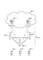
- FIG. 1 is a diagram showing a configuration of the LTE system.
- the LTE system includes a UE (User Equipment) 100, an E-UTRAN (Evolved UMTS Terrestrial Radio Access Network) 10, and an EPC (Evolved Packet Core) 20.
- the E-UTRAN 10 and the EPC 20 constitute an LTE system network.
- the UE 100 corresponds to a wireless terminal.
- the UE 100 is a mobile terminal.
- the UE 100 performs radio communication with a cell (serving cell).
- the configuration of the UE 100 will be described later.
- the E-UTRAN 10 corresponds to a radio access network.
- the E-UTRAN 10 includes an eNB 200 (evolved Node-B).
- the eNB 200 corresponds to a base station.
- the eNB 200 is connected to each other via the X2 interface. The configuration of the eNB 200 will be described later.
- ENB 200 manages one or a plurality of cells.
- eNB200 performs radio
- the eNB 200 has a radio resource management (RRM) function, a routing function of user data (hereinafter simply referred to as “data”), a measurement control function for mobility control / scheduling, and the like.
- RRM radio resource management
- data a routing function of user data
- Cell is used as a term indicating a minimum unit of a wireless communication area.
- Cell is also used as a term indicating a function of performing wireless communication with the UE 100.
- the EPC 20 corresponds to a core network.
- the EPC 20 includes an MME (Mobility Management Entity) / S-GW (Serving-Gateway) 300.
- MME Mobility Management Entity
- S-GW Serving-Gateway
- MME performs various mobility control etc. with respect to UE100.
- the S-GW performs data transfer control.
- the MME / S-GW 300 is connected to the eNB 200 via the S1 interface.
- the E-UTRAN 10 and the EPC 20 constitute a network.
- FIG. 2 is a diagram showing a protocol stack of a radio interface in the LTE system.
- the radio interface protocol is divided into the first to third layers of the OSI reference model, and the first layer is a physical (PHY) layer.
- the second layer includes a MAC (Medium Access Control) layer, an RLC (Radio Link Control) layer, and a PDCP (Packet Data Convergence Protocol) layer.
- the third layer includes an RRC (Radio Resource Control) layer.
- the physical layer, the MAC layer, the RLC layer, the PDCP layer, and the RRC layer constitute an AS (Access Stratum) entity 100a.
- the higher layer entity 100b is positioned in a higher layer than the AS entity 100a.
- the upper layer entity 100b includes a NAS (Non-Access Stratum) layer.
- the upper layer entity 100b may further include an application layer and the like.
- the physical layer performs encoding / decoding, modulation / demodulation, antenna mapping / demapping, and resource mapping / demapping.
- Data and control signals are transmitted between the physical layer of the UE 100 and the physical layer of the eNB 200 via a physical channel.
- the MAC layer performs data priority control, retransmission processing by hybrid ARQ (HARQ), random access procedure, and the like. Data and control signals are transmitted between the MAC layer of the UE 100 and the MAC layer of the eNB 200 via a transport channel.
- the MAC layer of the eNB 200 includes a scheduler. The scheduler determines the uplink / downlink transport format (transport block size, modulation / coding scheme (MCS)) and the resource blocks allocated to the UE 100.
- MCS modulation / coding scheme
- the RLC layer transmits data to the RLC layer on the receiving side using the functions of the MAC layer and the physical layer. Data and control signals are transmitted between the RLC layer of the UE 100 and the RLC layer of the eNB 200 via a logical channel.
- the PDCP layer performs header compression / decompression and encryption / decryption.
- the RRC layer is defined only in the control plane that handles control signals. Signaling for various settings (RRC signaling) is transmitted between the RRC layer of the UE 100 and the RRC layer of the eNB 200.
- the RRC layer controls the logical channel, the transport channel, and the physical channel according to establishment, re-establishment, and release of the radio bearer.
- RRC connection When there is a connection (RRC connection) between the RRC of the UE 100 and the RRC of the eNB 200, the UE 100 is in the RRC connected mode.
- RRC connection connection between the RRC of the UE 100 and the RRC of the eNB 200
- the UE 100 is in the RRC idle mode.
- the NAS layer located above the RRC layer performs session management and mobility management.
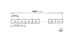
- FIG. 3 is a diagram illustrating a configuration of a radio frame used in the LTE system.
- OFDMA Orthogonal Frequency Division Multiple Access
- SC-FDMA Single Carrier Division Multiple Access
- the radio frame is composed of 10 subframes arranged in the time direction.
- Each subframe is composed of two slots arranged in the time direction.
- the length of each subframe is 1 ms, and the length of each slot is 0.5 ms.
- Each subframe includes a plurality of resource blocks (RB) in the frequency direction and includes a plurality of symbols in the time direction.
- Each resource block includes a plurality of subcarriers in the frequency direction.
- One symbol and one subcarrier constitute one resource element (RE).
- a frequency resource can be specified by a resource block, and a time resource can be specified by a subframe (or slot).
- FIG. 4 is a diagram illustrating a configuration of the UE 100 (radio terminal). As illustrated in FIG. 4, the UE 100 includes a reception unit 110, a transmission unit 120, and a control unit 130.
- the receiving unit 110 performs various types of reception under the control of the control unit 130.
- the receiving unit 110 includes an antenna and a receiver.
- the receiver converts a radio signal received by the antenna into a baseband signal (received signal).
- the receiver outputs a baseband signal to control unit 130.
- the transmission unit 120 performs various transmissions under the control of the control unit 130.
- the transmission unit 120 includes an antenna and a transmitter.
- the transmitter converts a baseband signal (transmission signal) output from the control unit 130 into a radio signal.
- the transmitter transmits a radio signal from the antenna.
- the control unit 130 performs various controls in the UE 100.
- the control unit 130 includes a processor and a memory.
- the memory stores a program executed by the processor and information used for processing by the processor.
- the processor may include a baseband processor and a CPU (Central Processing Unit).
- the baseband processor performs modulation / demodulation and encoding / decoding of the baseband signal.
- the CPU performs various processes by executing programs stored in the memory.
- the processor may include a codec that performs encoding / decoding of an audio / video signal.
- the processor executes various processes described above and various processes described later.
- FIG. 5 is a diagram illustrating a configuration of the eNB 200 (base station). As illustrated in FIG. 5, the eNB 200 includes a transmission unit 210, a reception unit 220, a control unit 230, and a backhaul communication unit 240.
- the transmission unit 210 performs various transmissions under the control of the control unit 230.
- the transmission unit 210 includes an antenna and a transmitter.
- the transmitter converts a baseband signal (transmission signal) output from the control unit 230 into a radio signal.
- the transmitter transmits a radio signal from the antenna.
- the receiving unit 220 performs various types of reception under the control of the control unit 230.
- the receiving unit 220 includes an antenna and a receiver.
- the receiver converts a radio signal received by the antenna into a baseband signal (received signal).
- the receiver outputs the baseband signal to the control unit 230.
- the control unit 230 performs various controls in the eNB 200.
- the control unit 230 includes a processor and a memory.
- the memory stores a program executed by the processor and information used for processing by the processor.
- the processor may include a baseband processor and a CPU (Central Processing Unit).
- the baseband processor performs modulation / demodulation and encoding / decoding of the baseband signal.
- the CPU performs various processes by executing programs stored in the memory.
- the processor executes various processes described above and various processes described later.
- the backhaul communication unit 240 is connected to the neighboring eNB 200 via the X2 interface.
- the backhaul communication unit 240 is connected to the MME / S-GW 300 via the S1 interface.
- the backhaul communication unit 240 is used for communication performed on the X2 interface, communication performed on the S1 interface, and the like.
- SS subcarrier spacing
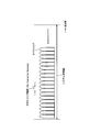
- FIG. 6 is a diagram showing an OFDM signal waveform.
- OFDM transmission is a type of multi-carrier modulation scheme that distributes data to a plurality of orthogonal subcarriers and transmits data in parallel in the frequency direction.
- the subcarrier interval refers to the interval between two adjacent subcarriers.
- the system bandwidth and / or the OFDM symbol length may be scalable. For example, the subcarrier interval may be increased and the OFDM symbol length may be shortened.
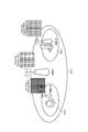
- FIG. 7 is a diagram illustrating an example of an assumed scenario according to the first embodiment.
- the eNB 200-1 manages the cell 1
- the eNB 200-2 manages the cell 2
- the eNB 200-3 manages the cell 3.
- an example in which one eNB 200 manages one cell is shown, but one eNB 200 may manage a plurality of cells.
- the cell 1 is a macro cell, and a subcarrier interval of 15 kHz is applied.
- the cell 2 is a small cell for outdoor, and a subcarrier interval of 30 kHz is applied.
- the cell 3 is a small cell for indoor use, and a subcarrier interval of 60 kHz is applied.
- FIG. 8 is a diagram showing an example of arrangement of synchronization signals.
- one partition in the vertical direction indicates one subcarrier
- one partition in the horizontal direction indicates one OFDM symbol.
- the subcarrier interval (SS) is 15 kHz.
- the synchronization signal is arranged in 6 resource blocks (6RB) in the center of the system bandwidth in the frequency direction. Specifically, the synchronization signal is arranged on a plurality of continuous subcarriers. In the time direction, the synchronization signal is arranged at a preset time position.
- the synchronization signal is the primary synchronization signal arranged in the last OFDM symbol of the first half slot every 5 subframes, and the second from the end of the same slot as the primary synchronization signal (ie, immediately before the primary synchronization signal). Secondary synchronization signals arranged in the OFDM symbols. When applied to a 5G system, the arrangement may not be the same as that of an existing LTE system.
- the UE 100 establishes synchronization with the cell by performing a cell search for searching for a synchronization signal of the cell, and identifies the cell. Therefore, the UE 100 cannot perform synchronization with the cell and identification of the cell unless the synchronization signal reception process (that is, the synchronization process) is successful.
- the subcarrier interval when the subcarrier interval is made scalable, the subcarrier interval (SS) is, for example, 30 kHz. Compared to FIG. 8A, the subcarrier interval is doubled and the OFDM symbol length is halved.
- the subcarrier interval of the synchronization signal can also be scalable. Therefore, the UE 100 may need to perform synchronization processing using all possible subcarrier intervals. However, such a method is not preferable from the viewpoint of the processing load of the UE 100.
- the eNB 200 uses a predetermined subcarrier interval, and in a cell managed by the eNB 200, based on the transmission unit 210 that transmits a synchronization signal and the predetermined subcarrier interval. And a control unit 230 that arranges synchronization signals on a plurality of subcarriers that are not continuous in the frequency direction (hereinafter referred to as “discrete subcarriers”).
- the time position where the synchronization signal is to be arranged is preset. That is, eNB 200 may transmit the synchronization signal on symbols arranged at the same time position regardless of the subcarrier interval.
- the control unit 230 arranges the synchronization signal on the discrete subcarriers when the predetermined subcarrier interval is narrower than the preset specified subcarrier interval. Specifically, in a scenario where there are a plurality of cells having different subcarrier intervals, the widest subcarrier interval is preset as the specified subcarrier interval. In the discrete subcarrier, the interval between two adjacent discrete subcarriers is equal to the specified subcarrier interval.
- the specified subcarrier interval is a subcarrier interval that the UE 100 uses for the reception process of the synchronization signal.
- the synchronization signal includes a signal sequence (code sequence) indicating a predetermined subcarrier interval.
- the UE100 which concerns on 1st Embodiment performs the reception process of a synchronizing signal using the predetermined
- the control unit 130 may perform the synchronization signal reception process at a preset time position. Based on the received signal sequence of the synchronization signal, the control unit 130 recognizes the subcarrier interval of the source cell of the synchronization signal.
- FIG. 9 is a diagram illustrating an operation example of the eNB 200 according to the first embodiment.
- cell 1 having a subcarrier interval (SS) of 15 kHz and cell 2 having a subcarrier interval (SS) of 30 kHz exist.
- Cell 1 and cell 2 may be managed by the same eNB 200, or may be managed by different eNBs 200.
- FIG. 9 illustrates a case where the cell 1 is managed by the eNB 200-1 and the cell 2 is managed by the eNB 200-2.
- the eNB 200-1 transmits the synchronization signal 1 in the cell 1 using the subcarrier interval of 15 kHz.
- the synchronization signal 1 includes a signal series 1 indicating 15 kHz.
- the eNB 200-2 transmits the synchronization signal 2 in the cell 2 using the 30-Hz subcarrier interval.
- the synchronization signal 2 includes a signal series 2 indicating 30 kHz.
- the subcarrier interval of 30 Hz corresponds to a preset predetermined subcarrier interval.
- the eNB 200-1 places the synchronization signal 1 on the discrete subcarriers because the subcarrier interval of the cell 1 is narrower than the specified subcarrier interval.
- the eNB 200-2 arranges the synchronization signal 2 on a plurality of subcarriers (continuous subcarriers) continuous in the frequency direction.
- the eNB 200-1 and the eNB 200-2 arrange the synchronization signals 1 and 2 at the same time position (predetermined symbol period).
- the interval between two adjacent discrete subcarriers is equal to the specified subcarrier interval.
- eNB 200-1 arranges synchronization signal 1 at a rate of one subcarrier every two subcarriers.
- the interval between the subcarriers where the synchronization signal 1 is arranged is equal to 30 kHz (the specified subcarrier interval).
- the UE 100 performs reception processing (synchronization processing) of a synchronization signal at a preset time position using 30 kHz which is a preset predetermined subcarrier interval. Thereby, the UE 100 can receive and demodulate the synchronization signal 1 of the cell 1 and the synchronization signal 2 of the cell 2 by the same signal processing. In other words, the UE 100 can also receive and demodulate the synchronization signal 1 of the cell 1 by signal processing similar to the reception processing used for the synchronization signal 2 of the cell 2.
- the UE100 recognizes the subcarrier space
- the UE 100 After recognizing the subcarrier interval of the cell, the UE 100 performs reception processing of other signals using the subcarrier interval.
- Other signals are, for example, cell-specific reference signals and system information (such as a master information block and a system information block).
- the UE 100 can start communication with the cell by receiving these signals.
- the eNB 200-1 arranges the synchronization signal 1 on the discrete subcarriers so that the subcarrier interval of the synchronization signal 1 becomes the specified subcarrier interval (30 kHz). To do.
- the UE 100 can perform the synchronization process with the cell 1 using the specified subcarrier interval (30 kHz). That is, the UE 100 can receive the synchronization signal 1 of the cell 1 and the synchronization signal 2 of the cell 2 by uniform synchronization processing. Therefore, even when the subcarrier interval is made scalable, an increase in the processing load on the UE 100 can be suppressed.
- the setting method of the specified subcarrier interval is not particularly mentioned.
- the prescribed subcarrier spacing may be predefined according to system specifications.
- the time position where the synchronization signal is arranged may be predefined according to the system specification.
- the specified subcarrier interval may be set and updated in the UE 100 and the eNB 200 by signaling from the core network or OAM (Operations Administration and Maintenance).
- OAM Operations Administration and Maintenance
- the time position at which the synchronization signal is arranged may be set and updated in the UE 100 and the eNB 200 by signaling from the core network or the OAM.
- the eNB 200 uses a predetermined subcarrier interval, and in a cell managed by the eNB 200, a transmission unit 210 that transmits a synchronization signal, and a time position that transmits the synchronization signal And a control unit 230 that applies a subcarrier interval different from the predetermined subcarrier interval.
- the eNB 200 applies a subcarrier interval different from other time positions (that is, data transmission subcarriers) only to the time position of the synchronization signal.
- control unit 230 applies the specified subcarrier interval to the time position at which the synchronization signal is transmitted when the predetermined subcarrier interval is different from the preset specified subcarrier interval.
- the time position where the synchronization signal is to be arranged may be set in advance.
- the synchronization signal includes a signal sequence indicating a predetermined subcarrier interval.
- the prescribed subcarrier interval is a subcarrier interval that UE 100 uses for reception processing of a synchronization signal.
- movement of UE100 it is the same as that of 1st Embodiment.
- FIG. 10 is a diagram illustrating an operation example of the eNB 200 according to the second embodiment.
- a case where the specified subcarrier interval is 15 kHz when there is a cell 2 having a subcarrier interval (SS) of 30 kHz is illustrated.
- Cell 2 is managed by the eNB 200-2.
- the eNB 200-2 transmits the synchronization signal 2 in the cell 2 using the subcarrier interval of 30 kHz.
- the eNB 200-2 applies the subcarrier interval of 15 kHz to the time position where the synchronization signal 2 is transmitted.
- the eNB 200-2 arranges the synchronization signal 2 at a preset time position.
- the UE 100 performs reception processing (synchronization processing) of the synchronization signal 2 at a preset time position using 15 kHz which is a preset predetermined subcarrier interval. Then, the UE 100 recognizes the subcarrier interval (30 kHz) of the cell 2 based on the received signal sequence of the synchronization signal 2. After recognizing the subcarrier interval of cell 2, UE 100 performs reception processing on other signals of cell 2 using the subcarrier interval. The UE 100 can start communication with the cell 2 by receiving these signals.
- the eNB 200 is different only in the time position of the synchronization signal from the other time positions (that is, subcarriers for data transmission)
- the specified subcarrier spacing of 15 kHz is applied.
- An eNB 200 includes a transmission unit 210 that transmits subcarrier interval information to the UE 100 in the first cell.
- the subcarrier interval information indicates a subcarrier interval of a second cell different from the first cell.
- the first cell may be a primary cell (PCell) of the UE 100
- the second cell may be a secondary cell (SCell) of the UE 100.
- the PCell may be a cell similar to an existing LTE cell
- the SCell may be a 5G mobile communication system cell.
- the UE 100 includes, in the first cell, a reception unit 110 that receives subcarrier interval information from the eNB 200, a control unit 230 that recognizes the subcarrier interval of the second cell based on the subcarrier interval information, Is provided.
- the control unit 230 performs reception processing of the synchronization signal of the second cell using the recognized subcarrier interval.
- FIG. 11 is a diagram illustrating an operation example of the eNB 200 and the UE 100 according to the third embodiment.
- the first cell (PCell) and the second cell (SCell) are managed by the same eNB 200 is illustrated.
- the subcarrier interval of the first cell (PCell) is 15 kHz
- the subcarrier interval of the second cell (SCell) is 30 kHz.
- the UE 100 has a connection with the first cell (PCell) and does not have a connection with the second cell (SCell).
- the eNB 200 transmits measurement configuration information (Measurement Config) including subcarrier interval information indicating the subcarrier interval of the second cell (SCell) to the UE 100 in the first cell (PCell).
- the measurement setting information is transmitted by dedicated RRC signaling. However, the measurement setting information may be transmitted by broadcast signaling.
- the measurement setting information may include not only the subcarrier interval information but also information indicating the center frequency of the second cell (SCell). Further, the measurement setting information may include information indicating a service provided by the second cell (SCell) (that is, the use of the cell 2).
- step S12 the UE 100 starts measurement on the second cell (SCell) based on the received measurement setting information.
- UE100 recognizes the subcarrier space
- step S13 the eNB 200 transmits a synchronization signal in the second cell (SCell).
- UE100 performs the reception process of the synchronizing signal of a 2nd cell (SCell) using the subcarrier space
- the UE 100 measures the reference signal of the second cell (SCell) and transmits the measurement result to the first cell (PCell).
- eNB200 transmits the setting information for adding a 2nd cell as SCell to UE100 based on a measurement result.
- UE100 performs the carrier aggregation which used the 1st cell (PCell) and the 2nd cell (SCell) simultaneously.
- one cell notifies the UE 100 of the subcarrier interval of another cell in advance.
- UE100 can receive the synchronizing signal of the said other cell easily. Therefore, even when the subcarrier interval is made scalable, an increase in the processing load on the UE 100 can be suppressed.
- the subcarrier interval information may be transmitted from the first cell (PCell) to the UE 100 by dedicated signaling.
- the subcarrier interval information may be transmitted from the first cell (PCell) by broadcast signaling.
- the subcarrier interval information may be a list of subcarrier intervals of a plurality of cells. The list may include a plurality of entries, and each entry may include a cell identifier and a subcarrier interval of the cell.
- the first cell and the second cell are managed by the same eNB 200
- the first cell may be managed by the eNB 200-1 and the second cell may be managed by the eNB 200-2.
- dual connectivity may be performed instead of carrier aggregation.
- the second cell may be referred to as a primary / secondary cell (PSCell).
- the eNB 200-2 may notify the eNB 200-1 of the subcarrier interval of the cell 2 via the backhaul. For example, the eNB 200-2 notifies the eNB 200-1 of the subcarrier interval of the cell 2 on the X2 interface or the S1 interface.
- the first to third embodiments described above may be implemented separately and independently, or may be implemented by combining two or more embodiments.
- the 5G mobile communication system is a system developed from the LTE system.
- the 5G mobile communication system includes LTE and a new radio access technology (new RAT).
- new RAT new radio access technology
- the present invention may be applied to a mobile communication system using such a new radio access technology.
- the first cell includes a transmission unit that transmits the subcarrier interval information to the wireless terminal,
- the subcarrier interval information is a base station indicating a subcarrier interval of a second cell different from the first cell.
- the first cell is a primary cell of the wireless terminal, The base station according to claim 11, wherein the second cell is a secondary cell of the wireless terminal.
- a receiving unit that receives subcarrier interval information from a base station, wherein the subcarrier interval information indicates a subcarrier interval of a second cell different from the first cell.
- a control unit for recognizing a subcarrier interval of the second cell based on the subcarrier interval information A wireless terminal comprising:
- the present invention is useful in the field of wireless communication.
Landscapes
- Engineering & Computer Science (AREA)
- Signal Processing (AREA)
- Computer Networks & Wireless Communication (AREA)
- Physics & Mathematics (AREA)
- Mathematical Physics (AREA)
- Databases & Information Systems (AREA)
- Mobile Radio Communication Systems (AREA)
Abstract
Priority Applications (6)
| Application Number | Priority Date | Filing Date | Title |
|---|---|---|---|
| EP17747182.8A EP3399820B1 (fr) | 2016-02-03 | 2017-01-16 | Station de base et terminal sans fil pour la recherche de cellule dans un environnement à numérologie mixte |
| EP22153170.0A EP4007415A1 (fr) | 2016-02-03 | 2017-01-16 | Station de base et terminal sans fil pour pour une connectivité double ou agrégation de porteuses dans un environnement à numérologie mixte |
| EP19205559.8A EP3629655B1 (fr) | 2016-02-03 | 2017-01-16 | Station de base et terminal radio en double connectivité avec multiple numérologies |
| JP2017565456A JP6526251B2 (ja) | 2016-02-03 | 2017-01-16 | 基地局及び無線端末 |
| US16/052,399 US10716077B2 (en) | 2016-02-03 | 2018-08-01 | Base station and radio terminal |
| US16/899,360 US11310752B2 (en) | 2016-02-03 | 2020-06-11 | Base station and radio terminal |
Applications Claiming Priority (2)
| Application Number | Priority Date | Filing Date | Title |
|---|---|---|---|
| JP2016018856 | 2016-02-03 | ||
| JP2016-018856 | 2016-02-03 |
Related Child Applications (1)
| Application Number | Title | Priority Date | Filing Date |
|---|---|---|---|
| US16/052,399 Continuation US10716077B2 (en) | 2016-02-03 | 2018-08-01 | Base station and radio terminal |
Publications (1)
| Publication Number | Publication Date |
|---|---|
| WO2017135020A1 true WO2017135020A1 (fr) | 2017-08-10 |
Family
ID=59500176
Family Applications (1)
| Application Number | Title | Priority Date | Filing Date |
|---|---|---|---|
| PCT/JP2017/001185 Ceased WO2017135020A1 (fr) | 2016-02-03 | 2017-01-16 | Station de base et terminal sans fil |
Country Status (4)
| Country | Link |
|---|---|
| US (2) | US10716077B2 (fr) |
| EP (3) | EP3399820B1 (fr) |
| JP (3) | JP6526251B2 (fr) |
| WO (1) | WO2017135020A1 (fr) |
Cited By (6)
| Publication number | Priority date | Publication date | Assignee | Title |
|---|---|---|---|---|
| US10582356B2 (en) | 2018-04-20 | 2020-03-03 | At&T Intellectual Property I, L.P. | Dynamic management of default subcarrier spacing for 5G or other next generation network |
| JP2021501497A (ja) * | 2017-10-31 | 2021-01-14 | テレフオンアクチーボラゲット エルエム エリクソン(パブル) | サブキャリア間隔ヌメロロジの指示 |
| US11638247B2 (en) | 2016-05-11 | 2023-04-25 | Interdigital Patent Holdings, Inc. | Physical (PHY) layer solutions to support use of mixed numerologies in the same channel |
| AU2022215175B2 (en) * | 2016-08-10 | 2023-07-13 | Interdigital Patent Holdings, Inc. | Methods for flexible resource usage |
| US11916709B2 (en) | 2016-03-10 | 2024-02-27 | Interdigital Patent Holdings, Inc. | Determination of a signal structure in a wireless system |
| US12349108B2 (en) | 2018-09-25 | 2025-07-01 | Interdigital Patent Holdings, Inc. | Methods, devices, and systems for supporting HARQ on V2X |
Families Citing this family (7)
| Publication number | Priority date | Publication date | Assignee | Title |
|---|---|---|---|---|
| EP4092936A3 (fr) | 2016-05-09 | 2023-04-05 | Samsung Electronics Co., Ltd. | Procédé et dispositif pour émettre/recevoir un signal de synchronisation dans un système de communication cellulaire sans fil |
| KR102677807B1 (ko) * | 2016-05-09 | 2024-06-25 | 삼성전자주식회사 | 무선 셀룰라 통신 시스템의 동기신호 송수신 방법 및 장치 |
| EP4224773B1 (fr) | 2016-08-22 | 2024-06-12 | Samsung Electronics Co., Ltd. | Procédé et appareil d'insertion d'un index de bloc de code dans un système de communication cellulaire sans fil |
| KR102683634B1 (ko) | 2016-08-22 | 2024-07-11 | 삼성전자 주식회사 | 통신 시스템에서 초기 접속을 수행하는 방법 및 장치 |
| US11916720B2 (en) * | 2016-09-30 | 2024-02-27 | Sony Group Corporation | Subcarrier spacing selection for synchronization signals |
| CN113067682B (zh) * | 2017-01-04 | 2023-04-07 | 华为技术有限公司 | 无线通信的方法和设备 |
| US10980015B2 (en) * | 2017-01-05 | 2021-04-13 | Nec Corporation | Methods and apparatuses for configuring radio terminal with numerology of second RAT via first RAT |
Family Cites Families (38)
| Publication number | Priority date | Publication date | Assignee | Title |
|---|---|---|---|---|
| JP2005244763A (ja) * | 2004-02-27 | 2005-09-08 | Fujitsu Ltd | 移動体端末 |
| US7969858B2 (en) * | 2004-10-14 | 2011-06-28 | Qualcomm Incorporated | Wireless terminal methods and apparatus for use in wireless communications systems supporting different size frequency bands |
| EA018838B1 (ru) * | 2006-06-16 | 2013-11-29 | Шарп Кабусики Кайся | Способ идентификации сектора, мобильная станция и система мобильной связи |
| JP4734426B2 (ja) * | 2007-02-08 | 2011-07-27 | 富士通株式会社 | 無線端末装置、基地局装置および無線通信方法 |
| US9137075B2 (en) * | 2007-02-23 | 2015-09-15 | Telefonaktiebolaget Lm Ericsson (Publ) | Subcarrier spacing identification |
| JP2010041687A (ja) * | 2008-08-08 | 2010-02-18 | Fujitsu Ltd | 無線通信装置および無線通信制御方法 |
| KR101527035B1 (ko) * | 2008-12-05 | 2015-06-09 | 엘지전자 주식회사 | 동기 채널과 필수 제어 정보 채널의 전송 방법 및 그 펨토 기지국 |
| EP2205030B1 (fr) * | 2009-01-06 | 2020-09-30 | Nokia Technologies Oy | Appareil et procédé de génération de canaux de synchronisation dans un système de communication sans fils |
| US9351185B2 (en) * | 2011-04-15 | 2016-05-24 | Broadcom Corporation | LTE carrier aggregation configuration on TV white space bands |
| US9198066B2 (en) * | 2012-02-29 | 2015-11-24 | Panasonic Intellectual Property Corporation Of America | Wireless communication device, wireless communication terminal, reference signal transmission control method, and reference signal processing method |
| US9549395B2 (en) * | 2012-04-30 | 2017-01-17 | Lg Electronics Inc. | Method for dynamic allocation of radio resources in wireless communication system and device therefor |
| WO2014042423A2 (fr) * | 2012-09-16 | 2014-03-20 | 엘지전자 주식회사 | Procédé par lequel un terminal reçoit un canal de contrôle de liaison descendante amélioré dans un système de communication sans fil, et appareil pour ce procédé |
| US9769811B2 (en) * | 2012-09-17 | 2017-09-19 | Lg Electronics Inc. | Method for receiving downlink control information in wireless communication system and device therefor |
| JP5814207B2 (ja) * | 2012-10-15 | 2015-11-17 | 株式会社Nttドコモ | 基地局装置及び移動端末装置 |
| US9398480B2 (en) * | 2012-11-02 | 2016-07-19 | Telefonaktiebolaget L M Ericsson (Publ) | Methods of obtaining measurements in the presence of strong and/or highly varying interference |
| US9985771B2 (en) * | 2012-11-27 | 2018-05-29 | Qualcomm Incorporated | Methods and apparatus for cooperating between wireless wide area network radios and wireless local area network radios |
| KR102243662B1 (ko) * | 2013-09-01 | 2021-04-23 | 엘지전자 주식회사 | 무선 통신 시스템에서 d2d(device-to-device) 통신을 위한 동기화 신호 전송 방법 및 이를 위한 장치 |
| WO2015042858A1 (fr) * | 2013-09-27 | 2015-04-02 | 华为技术有限公司 | Procédé de communication, équipement utilisateur et station de base |
| KR102057589B1 (ko) * | 2013-11-15 | 2019-12-19 | 삼성전자 주식회사 | 부분 네트워크 환경에서 단말 대 단말 통신을 위한 방법 및 장치 |
| EP2879425B1 (fr) * | 2013-11-28 | 2016-01-06 | NTT Docomo, Inc. | Découverte de petites cellules assistées de macrocellules et activation de ressources |
| EP3113394B1 (fr) * | 2014-02-28 | 2020-01-08 | LG Electronics Inc. | Procédé et appareil de production de signal pour un faible temps de latence dans un système de communication sans fil |
| JP6557249B6 (ja) * | 2014-04-09 | 2019-09-18 | エルジー エレクトロニクス インコーポレイティド | 移動セル用同期信号伝送方法及びこのための装置 |
| JP2016018856A (ja) | 2014-07-07 | 2016-02-01 | トヨタ紡織株式会社 | 基板保護カバー及び基板保護構造 |
| WO2016004634A1 (fr) * | 2014-07-11 | 2016-01-14 | Mediatek Singapore Pte. Ltd. | Procédé pour la transmission et la réception de liaison montante par un enb et un ue |
| EP3187014B1 (fr) * | 2014-08-28 | 2019-11-27 | Telefonaktiebolaget LM Ericsson (publ) | Procédés communiquant des informations de motif de rayonnement et noeuds de réseau et stations de base associés |
| US9961657B2 (en) * | 2014-09-25 | 2018-05-01 | Intel IP Corporation | System and method of MTC device operations |
| US20160242182A1 (en) * | 2015-02-12 | 2016-08-18 | Qualcomm Incorporated | Techniques for selecting uplink transmit antenna in multiple connectivity wireless communications |
| US10952193B2 (en) * | 2015-03-13 | 2021-03-16 | Qualcomm Incorporated | LTE-TDD carrier aggregation enhancement for half-duplex UES |
| US10128993B2 (en) * | 2015-05-29 | 2018-11-13 | Huawei Technologies Co., Ltd. | Systems and methods of adaptive frame structure for time division duplex |
| US10038581B2 (en) * | 2015-06-01 | 2018-07-31 | Huawei Technologies Co., Ltd. | System and scheme of scalable OFDM numerology |
| WO2016208897A1 (fr) * | 2015-06-22 | 2016-12-29 | 엘지전자 주식회사 | Procédé de transmission de canal de liaison montante et dispositif nb-ido |
| WO2017022870A1 (fr) * | 2015-08-03 | 2017-02-09 | Samsung Electronics Co., Ltd. | Procédé et appareil pour un accès initial dans un système de communication sans fil |
| US10757637B2 (en) | 2015-09-01 | 2020-08-25 | Ntt Docomo, Inc. | User terminal, radio base station, and radio communication method |
| US10117199B2 (en) * | 2015-09-24 | 2018-10-30 | Lg Electronics Inc. | Method of transmitting channel state information and apparatus therefor |
| US10742465B2 (en) * | 2015-10-29 | 2020-08-11 | Sharp Kabushiki Kaisha | Systems and methods for multi-physical structure system |
| JP2018207137A (ja) * | 2015-11-02 | 2018-12-27 | シャープ株式会社 | 基地局装置、端末装置および通信方法 |
| US11076387B2 (en) * | 2015-11-03 | 2021-07-27 | Samsung Electronics Co., Ltd. | Method and device for transmitting or receiving control information in wireless communication system |
| EP3393190B1 (fr) * | 2016-01-15 | 2022-02-23 | NTT DoCoMo, Inc. | Terminal utilisateur, station de base sans fil et procédé de communication sans fil |
-
2017
- 2017-01-16 WO PCT/JP2017/001185 patent/WO2017135020A1/fr not_active Ceased
- 2017-01-16 JP JP2017565456A patent/JP6526251B2/ja active Active
- 2017-01-16 EP EP17747182.8A patent/EP3399820B1/fr active Active
- 2017-01-16 EP EP22153170.0A patent/EP4007415A1/fr active Pending
- 2017-01-16 EP EP19205559.8A patent/EP3629655B1/fr active Active
-
2018
- 2018-08-01 US US16/052,399 patent/US10716077B2/en active Active
-
2019
- 2019-05-07 JP JP2019087623A patent/JP6758453B2/ja active Active
-
2020
- 2020-06-11 US US16/899,360 patent/US11310752B2/en active Active
- 2020-09-01 JP JP2020147168A patent/JP6964167B2/ja active Active
Non-Patent Citations (3)
| Title |
|---|
| HUAWEI ET AL.: "Synchronization Signal Design", 3GPP TSG-RAN WG1#83 R1-156464, 7 November 2015 (2015-11-07), XP051042042, Retrieved from the Internet <URL:http://www.3gpp.org/ftp/tsg_ran/WG1_RL1/TSGR1_83/Docs/> * |
| SHARP: "Synchronization signal design for NB-IoT", 3GPP TSG-RAN WG1#83 R1-157119, 6 November 2015 (2015-11-06), XP051042000, Retrieved from the Internet <URL:http://www.3gpp.org/ftp/tsg_ran/WG1_RL1/TSGR1_83/Docs/R1-157119.zip> * |
| ZTE: "Considerations on Synchronization Signal Design of NB-IoT", 3GPP TSG-RAN WG1#82B R1-155994, 30 September 2015 (2015-09-30), XP051021936, Retrieved from the Internet <URL:http://www.3gpp.org/ftp/tsg-ran/WG1-RL1/TSGR1-82b/Docs/R1-155994.zip> * |
Cited By (15)
| Publication number | Priority date | Publication date | Assignee | Title |
|---|---|---|---|---|
| US11916709B2 (en) | 2016-03-10 | 2024-02-27 | Interdigital Patent Holdings, Inc. | Determination of a signal structure in a wireless system |
| US12389426B2 (en) | 2016-05-11 | 2025-08-12 | Interdigital Patent Holdings, Inc. | Physical (PHY) layer solutions to support use of mixed numerologies in the same channel |
| US12058698B2 (en) | 2016-05-11 | 2024-08-06 | Interdigital Patent Holdings, Inc. | Physical (PHY) layer solutions to support use of mixed numerologies in the same channel |
| US11638247B2 (en) | 2016-05-11 | 2023-04-25 | Interdigital Patent Holdings, Inc. | Physical (PHY) layer solutions to support use of mixed numerologies in the same channel |
| AU2022215175B2 (en) * | 2016-08-10 | 2023-07-13 | Interdigital Patent Holdings, Inc. | Methods for flexible resource usage |
| US12238655B2 (en) | 2016-08-10 | 2025-02-25 | Interdigital Patent Holdings, Inc. | Methods for flexible resource usage |
| US11233689B2 (en) | 2017-10-31 | 2022-01-25 | Telefonaktiebolaget Lm Ericsson (Publ) | Indication of subcarrier spacing numerology |
| JP7299882B2 (ja) | 2017-10-31 | 2023-06-28 | テレフオンアクチーボラゲット エルエム エリクソン(パブル) | サブキャリア間隔ヌメロロジの指示 |
| US11736330B2 (en) | 2017-10-31 | 2023-08-22 | Telefonaktiebolaget Lm Ericsson (Publ) | Indication of subcarrier spacing numerology |
| US11398940B2 (en) | 2017-10-31 | 2022-07-26 | Telefonaktiebolaget Lm Ericsson (Publ) | Indication of subcarrier spacing numerology |
| US12132598B2 (en) | 2017-10-31 | 2024-10-29 | Telefonaktiebolaget Lm Ericsson (Publ) | Indication of subcarrier spacing numerology |
| JP2021501497A (ja) * | 2017-10-31 | 2021-01-14 | テレフオンアクチーボラゲット エルエム エリクソン(パブル) | サブキャリア間隔ヌメロロジの指示 |
| US10582356B2 (en) | 2018-04-20 | 2020-03-03 | At&T Intellectual Property I, L.P. | Dynamic management of default subcarrier spacing for 5G or other next generation network |
| US11012838B2 (en) | 2018-04-20 | 2021-05-18 | At&T Intellectual Property I, L.P. | Dynamic management of default subcarrier spacing for 5G or other next generation network |
| US12349108B2 (en) | 2018-09-25 | 2025-07-01 | Interdigital Patent Holdings, Inc. | Methods, devices, and systems for supporting HARQ on V2X |
Also Published As
| Publication number | Publication date |
|---|---|
| US20200305104A1 (en) | 2020-09-24 |
| JP6758453B2 (ja) | 2020-09-23 |
| JP2020205615A (ja) | 2020-12-24 |
| EP3399820A4 (fr) | 2019-01-09 |
| EP3399820A1 (fr) | 2018-11-07 |
| US11310752B2 (en) | 2022-04-19 |
| US20180376439A1 (en) | 2018-12-27 |
| JP6526251B2 (ja) | 2019-06-05 |
| US10716077B2 (en) | 2020-07-14 |
| JPWO2017135020A1 (ja) | 2018-11-29 |
| EP3399820B1 (fr) | 2019-12-04 |
| JP6964167B2 (ja) | 2021-11-10 |
| EP3629655A1 (fr) | 2020-04-01 |
| JP2019169956A (ja) | 2019-10-03 |
| EP4007415A1 (fr) | 2022-06-01 |
| EP3629655B1 (fr) | 2022-03-02 |
Similar Documents
| Publication | Publication Date | Title |
|---|---|---|
| JP6964167B2 (ja) | 基地局及び無線端末 | |
| JP6295316B2 (ja) | 基地局及びプロセッサ | |
| JP6026549B2 (ja) | 移動通信システム、基地局及びユーザ端末 | |
| JP2020031254A (ja) | 端末装置、基地局装置、通信方法、および、集積回路 | |
| JPWO2014017476A1 (ja) | 移動通信システム、基地局、ユーザ端末、及びプロセッサ | |
| WO2014129450A1 (fr) | Système de communication mobile, station de base, terminaux d'utilisateur et processeur | |
| US20190124641A1 (en) | Mobile communication system and user terminal | |
| JP5842061B2 (ja) | 移動通信システム、ユーザ端末、及びプロセッサ | |
| JP6532861B2 (ja) | 通信制御方法及び基地局 | |
| JP6515083B2 (ja) | ユーザ端末及び通信制御方法 | |
| JP6781692B2 (ja) | 通信装置及び通信方法 |
Legal Events
| Date | Code | Title | Description |
|---|---|---|---|
| 121 | Ep: the epo has been informed by wipo that ep was designated in this application |
Ref document number: 17747182 Country of ref document: EP Kind code of ref document: A1 |
|
| WWE | Wipo information: entry into national phase |
Ref document number: 2017565456 Country of ref document: JP Ref document number: 2017747182 Country of ref document: EP |
|
| NENP | Non-entry into the national phase |
Ref country code: DE |
|
| ENP | Entry into the national phase |
Ref document number: 2017747182 Country of ref document: EP Effective date: 20180801 |