WO2017135081A1 - Système d'étalonnage de caméra monté dans un véhicule - Google Patents
Système d'étalonnage de caméra monté dans un véhicule Download PDFInfo
- Publication number
- WO2017135081A1 WO2017135081A1 PCT/JP2017/002092 JP2017002092W WO2017135081A1 WO 2017135081 A1 WO2017135081 A1 WO 2017135081A1 JP 2017002092 W JP2017002092 W JP 2017002092W WO 2017135081 A1 WO2017135081 A1 WO 2017135081A1
- Authority
- WO
- WIPO (PCT)
- Prior art keywords
- vehicle
- camera
- camera calibration
- calibration system
- calculation unit
- Prior art date
- Legal status (The legal status is an assumption and is not a legal conclusion. Google has not performed a legal analysis and makes no representation as to the accuracy of the status listed.)
- Ceased
Links
Images





Classifications
-
- G—PHYSICS
- G06—COMPUTING OR CALCULATING; COUNTING
- G06T—IMAGE DATA PROCESSING OR GENERATION, IN GENERAL
- G06T7/00—Image analysis
- G06T7/80—Analysis of captured images to determine intrinsic or extrinsic camera parameters, i.e. camera calibration
-
- B—PERFORMING OPERATIONS; TRANSPORTING
- B60—VEHICLES IN GENERAL
- B60R—VEHICLES, VEHICLE FITTINGS, OR VEHICLE PARTS, NOT OTHERWISE PROVIDED FOR
- B60R11/00—Arrangements for holding or mounting articles, not otherwise provided for
- B60R11/04—Mounting of cameras operative during drive; Arrangement of controls thereof relative to the vehicle
-
- G—PHYSICS
- G06—COMPUTING OR CALCULATING; COUNTING
- G06T—IMAGE DATA PROCESSING OR GENERATION, IN GENERAL
- G06T7/00—Image analysis
- G06T7/20—Analysis of motion
- G06T7/246—Analysis of motion using feature-based methods, e.g. the tracking of corners or segments
-
- H—ELECTRICITY
- H04—ELECTRIC COMMUNICATION TECHNIQUE
- H04N—PICTORIAL COMMUNICATION, e.g. TELEVISION
- H04N17/00—Diagnosis, testing or measuring for television systems or their details
- H04N17/002—Diagnosis, testing or measuring for television systems or their details for television cameras
-
- H—ELECTRICITY
- H04—ELECTRIC COMMUNICATION TECHNIQUE
- H04N—PICTORIAL COMMUNICATION, e.g. TELEVISION
- H04N23/00—Cameras or camera modules comprising electronic image sensors; Control thereof
- H04N23/60—Control of cameras or camera modules
-
- H—ELECTRICITY
- H04—ELECTRIC COMMUNICATION TECHNIQUE
- H04N—PICTORIAL COMMUNICATION, e.g. TELEVISION
- H04N25/00—Circuitry of solid-state image sensors [SSIS]; Control thereof
- H04N25/60—Noise processing, e.g. detecting, correcting, reducing or removing noise
- H04N25/61—Noise processing, e.g. detecting, correcting, reducing or removing noise the noise originating only from the lens unit, e.g. flare, shading, vignetting or "cos4"
-
- H—ELECTRICITY
- H04—ELECTRIC COMMUNICATION TECHNIQUE
- H04N—PICTORIAL COMMUNICATION, e.g. TELEVISION
- H04N7/00—Television systems
- H04N7/18—Closed-circuit television [CCTV] systems, i.e. systems in which the video signal is not broadcast
- H04N7/183—Closed-circuit television [CCTV] systems, i.e. systems in which the video signal is not broadcast for receiving images from a single remote source
-
- B—PERFORMING OPERATIONS; TRANSPORTING
- B60—VEHICLES IN GENERAL
- B60R—VEHICLES, VEHICLE FITTINGS, OR VEHICLE PARTS, NOT OTHERWISE PROVIDED FOR
- B60R2300/00—Details of viewing arrangements using cameras and displays, specially adapted for use in a vehicle
- B60R2300/40—Details of viewing arrangements using cameras and displays, specially adapted for use in a vehicle characterised by the details of the power supply or the coupling to vehicle components
- B60R2300/402—Image calibration
-
- G—PHYSICS
- G06—COMPUTING OR CALCULATING; COUNTING
- G06T—IMAGE DATA PROCESSING OR GENERATION, IN GENERAL
- G06T2207/00—Indexing scheme for image analysis or image enhancement
- G06T2207/30—Subject of image; Context of image processing
- G06T2207/30248—Vehicle exterior or interior
- G06T2207/30252—Vehicle exterior; Vicinity of vehicle
Definitions
- the present disclosure relates to an in-vehicle camera calibration system that calibrates a camera image using an image captured by a camera.
- the situation immediately behind the vehicle which is a blind spot from the driver, can be visually recognized as an image displayed on the in-vehicle monitor, and viewed when the vehicle is moving backward It is done to improve the sex.
- a calibration target is installed behind the vehicle in order to correct the mounting state of the in-vehicle camera on the vehicle. Then, while viewing the image of the calibration target reflected on the vehicle-mounted monitor, the mounting state of the vehicle-mounted camera is adjusted so that the image of the calibration target is appropriately projected.
- an image displayed on the in-vehicle monitor is appropriately calibrated by applying a predetermined arithmetic processing based on the image of the calibration target to the image obtained by the in-vehicle camera.
- the entire periphery of the vehicle is photographed by a plurality of in-vehicle cameras, and the plurality of images obtained by each in-vehicle camera are converted into images (overhead images) that look down from directly above the vehicle.
- a single viewpoint-converted composite image is also obtained by performing mapping with adjusted positions between the images. In such a case, since it is necessary to perform alignment between two adjacent images with high accuracy, high-precision calibration is required.
- the vehicle production line has been devised to improve the alignment accuracy between the vehicle and the calibration target by modifying the equipment at an expense.
- the calibration target must be installed accurately each time. There is a need. For this reason, it takes much more work.
- a white line grid is used as a calibration target, and features that are irrelevant to the stop state of the vehicle, such as linearity, parallelism, orthogonality, and spacing of the white line grid, are used. Techniques have been proposed for calibrating internal / distortion parameters and external parameters.
- Patent Document 2 proposes a method of calibrating using a calibration target and a calibration accuracy evaluation target integrated.
- Patent Documents 1 and 2 it is necessary to stop the vehicle in the calibration target. In the factory production line, for each vehicle, an operator stops the vehicle in the calibration target ( Cost).
- the present disclosure has been made in view of such a point, and an object thereof is to provide an in-vehicle camera calibration system that can calibrate an in-vehicle camera without stopping the vehicle on a production line.
- the in-vehicle camera calibration system includes a camera, a memory, a feature point extraction unit, a tracking point extraction unit, and a camera calibration parameter calculation unit.
- the camera is attached to the vehicle and takes images of the road surface in time series.
- the memory stores images taken by the camera in time series.
- the feature point extraction unit extracts feature points from the captured image stored in the memory.
- the tracking point extraction unit extracts a tracking point that is a destination of the feature point after a predetermined time has elapsed.
- the camera calibration parameter calculation unit calculates camera calibration parameters from the feature points and tracking points.
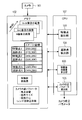
- FIG. 1 is a block diagram illustrating a functional configuration of a camera calibration device according to a first embodiment of the present disclosure.
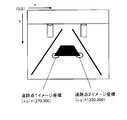
- saved at memory The figure which shows the image coordinate of the tracking point of the N + 1th image preserve
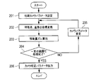
- Flowchart for calculating camera calibration parameters Flowchart for converting feature point image coordinates and tracking point image coordinates stored in memory to world coordinates Diagram explaining the coordinate axes in world coordinates and rotation around each coordinate axis Diagram explaining the coordinate axes in world coordinates and rotation around each coordinate axis Diagram explaining the process of converting image coordinates of feature points and tracking points to world coordinates
- the flowchart explaining the process of the moving body moving amount calculation part which calculates the moving amount of a moving body The figure explaining the
- FIG. 1 is a block diagram illustrating a functional configuration of the camera calibration apparatus according to the first embodiment of the present disclosure.
- the configuration and operation of the camera calibration apparatus according to the present embodiment will be described with reference to FIG.
- the camera calibration device of the present embodiment is installed on a moving body such as a vehicle.
- This camera calibration apparatus calibrates the camera 101, and includes a memory 102, a feature point extraction unit 103, a tracking point extraction unit 104, and a camera calibration parameter calculation unit 105.
- FIG. 1 also shows a vehicle 106.
- Each of the feature point extraction unit 103, the tracking point extraction unit 104, and the camera calibration parameter calculation unit 105 includes a CPU (Central Processing Unit) 107 in a camera calibration device in a ROM (Read Only Memory, not shown). This is realized by executing the stored program. Note that each unit may be realized by a dedicated circuit configured by hardware instead of using the CPU and ROM.
- CPU Central Processing Unit
- ROM Read Only Memory
- the camera 101 is installed in a vehicle and stores in the memory 102 images chronologically captured images of the road surface while the vehicle is moving.
- the feature point extraction unit 103 extracts feature points from the Nth image stored in the memory 102 as shown in FIG. 2 and stores the image coordinates of the feature points in the memory 102.
- the image coordinates are a two-dimensional coordinate system having the origin at the upper left of the image placed on the memory.
- a feature point is a point at which a luminance information amount in a predetermined range including the point has a characteristic size. For example, a Harris corner point or the like is searched for as the feature point.
- the tracking point extraction unit 104 extracts a point having the same feature as the feature point from the (N + 1) th image stored in the memory 102 as illustrated in FIG. 3 as a tracking point, and stores the image coordinates of the tracking point in the memory 102. To do.
- the tracking point is extracted using a processing method such as the Kanade-Lucas-Tomasi method (the KLT).
- the camera calibration parameter calculation unit 105 calculates camera calibration parameters. Hereinafter, the process performed by the camera calibration parameter calculation unit 105 will be described in detail with reference to FIG.
- the camera calibration parameter calculation unit 105 sets the camera angle (pan, tilt, roll) and camera position of the camera mounting design value as initial camera parameters.
- the camera calibration parameter calculation unit 105 converts the image coordinates of the feature points and the image coordinates of the tracking points stored in the memory 102 into world coordinates. Details of the processing in step 202 will be described later.
- the camera calibration parameter calculation unit 105 calculates the movement amount of each feature point and tracking point on the world coordinates and the movement amount of the actual moving object stored in the memory 102. Is calculated as a shift in the movement amount. Details of the processing in step 203 will be described later.
- the camera calibration parameter calculation unit 105 changes the camera parameters within a certain range, and repeats the processing of Step 202-203 (Step 204: NO, 205).
- the camera calibration parameter calculation unit 105 uses the displacement of the movement amount as the evaluation value. To do. Then, the camera parameter (camera angle, position) that minimizes the evaluation value is used as a camera calibration parameter indicating the correspondence between the camera image and the actual road, and the camera calibration parameter is a camera image calibration device (not shown). Output to.
- the camera image calibration apparatus appropriately calibrates an image displayed on an in-vehicle monitor (not shown) using camera calibration parameters.
- step 202 feature point and tracking point coordinate conversion processing (step 202), that is, image coordinates of the feature point and tracking point stored in the memory 102 are converted into world coordinates. Details of the processing to be performed will be described.
- the world coordinates are a three-dimensional coordinate system in the real world, and the expressions (1) to (4) are the world coordinates (X W , Y W , Z W ) and the camera coordinates (X C , Y C , Z C ).
- the relationship between world coordinates and camera coordinates is determined by parameters of a rotation matrix R and a parallel progression T.
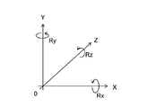
- the X axis, the Y axis, and the Z axis are provided as shown in FIG. 6A.
- FIG. 6A when the X-axis, Y-axis, and Z-axis are each viewed in the positive direction from the origin, the direction of rotating counterclockwise around each axis is defined as the positive direction of rotation.
- Rx represents a rotation angle with respect to the X axis
- Ry represents a rotation angle with respect to the Y axis
- Rz represents a rotation angle with respect to the Z axis.
- the direction turning counterclockwise with respect to the direction from the origin toward the positive direction is set as the positive direction of Rz.
- Rx and Ry are the same applies.
- the camera calibration parameter calculation unit 105 converts the input image coordinates (image x coordinate, image y coordinate) into distorted sensor coordinates (distorted sensor x coordinate, distorted sensor y coordinate).
- Expressions (5) and (6) are expressions showing the relationship between image coordinates and sensor coordinates with distortion. For the pixel pitch and image center in the x and y directions, values stored in the memory 102 as camera internal parameters are used.
- the camera calibration parameter calculation unit 105 converts the sensor coordinates with distortion into sensor coordinates without distortion (sensor x coordinates without distortion, sensor y coordinates without distortion).
- Expressions (7) to (9) are expressions indicating the relationship between the sensor coordinates with distortion and the sensor coordinates without distortion.
- kappa1 is a lens distortion correction coefficient, which is a known value.
- the lens distortion correction coefficient uses a value stored in the memory 102 as an internal camera parameter.
- step 303 the camera calibration parameter calculation unit 105 converts the sensor coordinates without distortion into world coordinates.
- Expressions (10) to (14) are expressions showing the relationship between the sensor coordinates without distortion and the world coordinates.
- Equation (10) can be converted into equation for camera x-coordinate X C.
- Expression (12) can be converted into an expression for obtaining the camera y coordinate Y C.
- the camera calibration parameter calculation unit 105 A three-dimensional equation in Expression (14) is derived from Expression (1), Expression (11), and Expression (13), and the world x coordinate Xw and the world z coordinate Zw can be calculated.
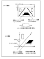
- the image coordinates of each feature point and tracking point are converted into points of world coordinates as shown in FIG.
- the point dropped from the vertex of the optical axis of the camera perpendicular to the road surface is used as the origin, and the image coordinate values shown in FIG. 2 are used as an example.
- the camera calibration parameter calculation unit 105 calculates the movement amount on the world coordinate in the Z-axis direction and the X-axis direction from the feature point and the tracking point converted into the world coordinate by Expression (15).
- the camera calibration parameter calculation unit 105 calculates the difference between the movement amount of each feature point and tracking point in the world coordinates and the movement amount of the actual moving object stored in the memory 102 by the equation (16). Calculated as the amount of deviation.
- the actual amount of movement of the moving body is calculated based on information about the amount of movement acquired from the vehicle 106 (vehicle speed pulse, steering angle information, vehicle speed, etc.) and stored in the memory 102. If there is no deviation in the attachment of the camera, the deviation between the movement amount calculated using the camera parameters and the actual movement amount of the vehicle is “0”.
- the displacement (evaluation value) of the moving amount is
- 30.
- the camera calibration parameter is calculated by calculating the movement amount in the real world using the feature point and the tracking point on the image taken while the vehicle is moving. Therefore, the camera calibration can be automatically performed when the vehicle moves on the production line without stopping the vehicle on the production line.
- FIG. 9 is a block diagram illustrating a functional configuration of the camera calibration apparatus according to the second embodiment of the present disclosure.
- the camera calibration apparatus shown in FIG. 9 employs a configuration in which a moving body movement amount calculation unit 806 is added in the CPU 107, as compared with the camera calibration apparatus shown in FIG.
- the moving body moving amount calculation unit 806 calculates the moving amount of the moving body (vehicle).
- vehicle vehicle
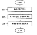
- details of the processing of the moving body movement amount calculation unit 806 will be described with reference to FIG.
- the moving body movement amount calculation unit 806 calculates the relative translation of the camera 101 from the basic matrix F and the focal length f according to Expression (18).
- a matrix T (unit matrix) and a rotation matrix R are calculated.
- Matrix-T ⁇ E is subjected to singular value decomposition as represented by (Equation 19).
- step 903 the moving body movement calculation unit 806 calculates the movement in the real world from the relative parallel progression T and the rotation matrix R of the camera.
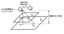
- step 903 will be described in detail with reference to FIG.
- a point (feature point) in the camera camera coordinates before movement is represented by P0
- a point (tracking point) in the vehicle camera coordinates after movement is represented by P'0.
- the relationship between P0 and P′0 is expressed by Expression (21).
- Equation (22) The normal vector of the plane represented by Equation (22) is (a, b, c), and the equation of a straight line orthogonal to this plane is represented by Equation (23).
- the moving body movement amount calculation unit 806 calculates a perpendicular line from the origin of the camera coordinates to the plane, and obtains the coordinates of the intersection C0 according to Expression (24).
- the moving body moving amount calculating unit 806 extends a straight line connecting the camera coordinate origin and C1, and calculates a point C1 equal to the camera height using the formula (Equation 25) of the distance between the point and the plane. That is, the distance D between the plane p0 represented by the equation (22) and the point C0 (x0, y0, z0) is
- the camera can be automatically calibrated when the vehicle moves on the production line without stopping the vehicle on the production line. .
- the invention according to the present disclosure is used in an in-vehicle camera calibration system that calibrates a camera using an image taken by a camera.
Landscapes
- Engineering & Computer Science (AREA)
- Multimedia (AREA)
- Signal Processing (AREA)
- Theoretical Computer Science (AREA)
- Physics & Mathematics (AREA)
- General Physics & Mathematics (AREA)
- Computer Vision & Pattern Recognition (AREA)
- Health & Medical Sciences (AREA)
- Biomedical Technology (AREA)
- General Health & Medical Sciences (AREA)
- Mechanical Engineering (AREA)
- Image Analysis (AREA)
- Studio Devices (AREA)
- Image Processing (AREA)
- Closed-Circuit Television Systems (AREA)
Abstract
L'invention concerne un système d'étalonnage de caméra monté dans un véhicule qui effectue un étalonnage de caméra automatiquement lorsqu'un véhicule est déplacé dans une chaîne de montage sans arrêter celui-ci sur la chaîne de montage. Le système d'étalonnage de caméra monté dans un véhicule comprend une caméra qui est fixée au véhicule et qui capture une image d'une surface de route en série chronologique; une mémoire dans laquelle l'image capturée par la caméra est stockée en série chronologique; une unité d'extraction de point caractéristique qui extrait un point caractéristique de l'image capturée stockée dans la mémoire; une unité d'extraction de point de suivi qui extrait un point de suivi vers lequel le point caractéristique se déplace au bout d'une durée prédéterminée; et une unité de calcul de paramètre d'étalonnage de caméra qui calcule un paramètre d'étalonnage de caméra à partir du point caractéristique et du point de suivi.
Priority Applications (1)
| Application Number | Priority Date | Filing Date | Title |
|---|---|---|---|
| US15/997,806 US20180286078A1 (en) | 2016-02-03 | 2018-06-05 | Vehicle-mounted camera calibration system |
Applications Claiming Priority (2)
| Application Number | Priority Date | Filing Date | Title |
|---|---|---|---|
| JP2016019072A JP2017139612A (ja) | 2016-02-03 | 2016-02-03 | 車載カメラ用校正システム |
| JP2016-019072 | 2016-02-03 |
Related Child Applications (1)
| Application Number | Title | Priority Date | Filing Date |
|---|---|---|---|
| US15/997,806 Continuation US20180286078A1 (en) | 2016-02-03 | 2018-06-05 | Vehicle-mounted camera calibration system |
Publications (1)
| Publication Number | Publication Date |
|---|---|
| WO2017135081A1 true WO2017135081A1 (fr) | 2017-08-10 |
Family
ID=59499726
Family Applications (1)
| Application Number | Title | Priority Date | Filing Date |
|---|---|---|---|
| PCT/JP2017/002092 Ceased WO2017135081A1 (fr) | 2016-02-03 | 2017-01-23 | Système d'étalonnage de caméra monté dans un véhicule |
Country Status (3)
| Country | Link |
|---|---|
| US (1) | US20180286078A1 (fr) |
| JP (1) | JP2017139612A (fr) |
| WO (1) | WO2017135081A1 (fr) |
Cited By (3)
| Publication number | Priority date | Publication date | Assignee | Title |
|---|---|---|---|---|
| WO2020129286A1 (fr) * | 2018-12-19 | 2020-06-25 | クラリオン株式会社 | Dispositif d'étalonnage et procédé d'étalonnage |
| CN113120080A (zh) * | 2021-04-12 | 2021-07-16 | 沈阳中科创达软件有限公司 | 倒车辅助线的建立方法、装置、终端及存储介质 |
| CN114347917A (zh) * | 2021-12-28 | 2022-04-15 | 华人运通(江苏)技术有限公司 | 一种车辆、车载摄像系统的校准方法和装置 |
Families Citing this family (21)
| Publication number | Priority date | Publication date | Assignee | Title |
|---|---|---|---|---|
| US10504241B2 (en) * | 2016-12-19 | 2019-12-10 | Magna Electronics Inc. | Vehicle camera calibration system |
| US10435173B2 (en) * | 2017-01-16 | 2019-10-08 | The Boeing Company | Remote optical control surface indication system |
| JP6846640B2 (ja) * | 2017-09-15 | 2021-03-24 | パナソニックIpマネジメント株式会社 | 車載カメラ校正装置 |
| JP2019061510A (ja) * | 2017-09-27 | 2019-04-18 | 国立研究開発法人農業・食品産業技術総合研究機構 | 車載カメラの取付高さパラメータ算出装置および取付高さパラメータ算出方法 |
| JP6890293B2 (ja) * | 2017-11-06 | 2021-06-18 | パナソニックIpマネジメント株式会社 | カメラ校正装置、カメラ校正システム、カメラ校正方法及びプログラム |
| CN108769576B (zh) * | 2018-05-10 | 2021-02-02 | 郑州信大先进技术研究院 | 智能视频处理方法和系统 |
| CN109859278B (zh) * | 2019-01-24 | 2023-09-01 | 惠州市德赛西威汽车电子股份有限公司 | 车载相机系统相机外参的标定方法及标定系统 |
| CN111508027B (zh) * | 2019-01-31 | 2023-10-20 | 杭州海康威视数字技术股份有限公司 | 摄像机外参标定的方法和装置 |
| JP7169227B2 (ja) * | 2019-02-28 | 2022-11-10 | 株式会社デンソーテン | 異常検出装置、および異常検出方法 |
| JP7217577B2 (ja) * | 2019-03-20 | 2023-02-03 | フォルシアクラリオン・エレクトロニクス株式会社 | キャリブレーション装置、キャリブレーション方法 |
| CN112132902B (zh) * | 2019-06-24 | 2024-01-16 | 上海安亭地平线智能交通技术有限公司 | 车载摄像头外参调整方法、装置、电子设备以及介质 |
| JP7237773B2 (ja) * | 2019-08-23 | 2023-03-13 | 株式会社デンソーテン | 姿勢推定装置、異常検出装置、補正装置、および、姿勢推定方法 |
| US12241960B1 (en) * | 2019-09-06 | 2025-03-04 | Apple Inc. | Determining relative electronic device positioning based on fusing ultra-wideband data and visual data |
| CN110619664B (zh) * | 2019-09-17 | 2023-06-27 | 武汉理工大学 | 基于激光图案辅助的摄像机距离姿态计算方法及服务器 |
| CN110827358B (zh) * | 2019-10-15 | 2023-10-31 | 深圳数翔科技有限公司 | 一种应用于自动驾驶汽车的相机标定方法 |
| CN111223150A (zh) * | 2020-01-15 | 2020-06-02 | 电子科技大学 | 一种基于双消失点的车载摄像头外参数标定方法 |
| KR20220026422A (ko) * | 2020-08-25 | 2022-03-04 | 삼성전자주식회사 | 카메라 캘리브레이션 장치 및 이의 동작 방법 |
| CN112562014B (zh) * | 2020-12-29 | 2024-07-02 | 纵目科技(上海)股份有限公司 | 相机标定方法、系统、介质及装置 |
| CN114387350A (zh) * | 2021-12-03 | 2022-04-22 | 江铃汽车股份有限公司 | 一种车载摄像机外参标定方法、装置、存储介质及设备 |
| CN114926550B (zh) * | 2022-06-09 | 2025-04-08 | 上海同陆云交通科技有限公司 | 一种多车后装相机视角自适应方法及系统 |
| CN117597705A (zh) * | 2022-06-13 | 2024-02-23 | 北京小米移动软件有限公司 | 一种摄像头的标定方法、装置及可读存储介质 |
Citations (5)
| Publication number | Priority date | Publication date | Assignee | Title |
|---|---|---|---|---|
| JP2007256029A (ja) * | 2006-03-23 | 2007-10-04 | Denso It Laboratory Inc | ステレオ画像処理装置 |
| JP2007263669A (ja) * | 2006-03-28 | 2007-10-11 | Denso It Laboratory Inc | 3次元座標取得装置 |
| JP2011217233A (ja) * | 2010-04-01 | 2011-10-27 | Alpine Electronics Inc | 車載カメラ校正システム及びコンピュータプログラム |
| JP2014048803A (ja) * | 2012-08-30 | 2014-03-17 | Denso Corp | 画像処理装置、及びプログラム |
| JP2014165810A (ja) * | 2013-02-27 | 2014-09-08 | Fujitsu Ten Ltd | パラメータ取得装置、パラメータ取得方法及びプログラム |
Family Cites Families (3)
| Publication number | Priority date | Publication date | Assignee | Title |
|---|---|---|---|---|
| JP2009017462A (ja) * | 2007-07-09 | 2009-01-22 | Sanyo Electric Co Ltd | 運転支援システム及び車両 |
| JP4831374B2 (ja) * | 2009-03-27 | 2011-12-07 | アイシン・エィ・ダブリュ株式会社 | 運転支援装置、運転支援方法、及び運転支援プログラム |
| JP6107081B2 (ja) * | 2012-11-21 | 2017-04-05 | 富士通株式会社 | 画像処理装置、画像処理方法及びプログラム |
-
2016
- 2016-02-03 JP JP2016019072A patent/JP2017139612A/ja active Pending
-
2017
- 2017-01-23 WO PCT/JP2017/002092 patent/WO2017135081A1/fr not_active Ceased
-
2018
- 2018-06-05 US US15/997,806 patent/US20180286078A1/en not_active Abandoned
Patent Citations (5)
| Publication number | Priority date | Publication date | Assignee | Title |
|---|---|---|---|---|
| JP2007256029A (ja) * | 2006-03-23 | 2007-10-04 | Denso It Laboratory Inc | ステレオ画像処理装置 |
| JP2007263669A (ja) * | 2006-03-28 | 2007-10-11 | Denso It Laboratory Inc | 3次元座標取得装置 |
| JP2011217233A (ja) * | 2010-04-01 | 2011-10-27 | Alpine Electronics Inc | 車載カメラ校正システム及びコンピュータプログラム |
| JP2014048803A (ja) * | 2012-08-30 | 2014-03-17 | Denso Corp | 画像処理装置、及びプログラム |
| JP2014165810A (ja) * | 2013-02-27 | 2014-09-08 | Fujitsu Ten Ltd | パラメータ取得装置、パラメータ取得方法及びプログラム |
Cited By (6)
| Publication number | Priority date | Publication date | Assignee | Title |
|---|---|---|---|---|
| WO2020129286A1 (fr) * | 2018-12-19 | 2020-06-25 | クラリオン株式会社 | Dispositif d'étalonnage et procédé d'étalonnage |
| JP2020098550A (ja) * | 2018-12-19 | 2020-06-25 | クラリオン株式会社 | キャリブレーション装置、キャリブレーション方法 |
| JP7191671B2 (ja) | 2018-12-19 | 2022-12-19 | フォルシアクラリオン・エレクトロニクス株式会社 | キャリブレーション装置、キャリブレーション方法 |
| CN113120080A (zh) * | 2021-04-12 | 2021-07-16 | 沈阳中科创达软件有限公司 | 倒车辅助线的建立方法、装置、终端及存储介质 |
| CN114347917A (zh) * | 2021-12-28 | 2022-04-15 | 华人运通(江苏)技术有限公司 | 一种车辆、车载摄像系统的校准方法和装置 |
| CN114347917B (zh) * | 2021-12-28 | 2023-11-10 | 华人运通(江苏)技术有限公司 | 一种车辆、车载摄像系统的校准方法和装置 |
Also Published As
| Publication number | Publication date |
|---|---|
| JP2017139612A (ja) | 2017-08-10 |
| US20180286078A1 (en) | 2018-10-04 |
Similar Documents
| Publication | Publication Date | Title |
|---|---|---|
| WO2017135081A1 (fr) | Système d'étalonnage de caméra monté dans un véhicule | |
| JP6154905B2 (ja) | カメラ校正装置、カメラ校正システム、及びカメラ校正方法 | |
| US8452568B2 (en) | Method for calibrating cameras installed on vehicle | |
| JP5811327B2 (ja) | カメラキャリブレーション装置 | |
| CN100573586C (zh) | 一种双目立体测量系统的标定方法 | |
| JP6260891B2 (ja) | 画像処理装置および画像処理方法 | |
| CN112967344B (zh) | 相机外参标定的方法、设备、存储介质及程序产品 | |
| US20130135474A1 (en) | Automotive Camera System and Its Calibration Method and Calibration Program | |
| EP3332387B1 (fr) | Procédé d'étalonnage d'une caméra stéréo | |
| JP2009042162A (ja) | キャリブレーション装置及びその方法 | |
| JP4857143B2 (ja) | カメラ姿勢算出用ターゲット装置およびこれを用いたカメラ姿勢算出方法ならびに画像表示方法 | |
| WO2015198930A1 (fr) | Dispositif de mesure de distance, et dispositif de correction de mesure de distance à l'aide d'un paramètre de correction | |
| JP5228614B2 (ja) | パラメータ計算装置、パラメータ計算システムおよびプログラム | |
| JP7308227B2 (ja) | 画像処理装置、および画像処理方法、並びにプログラム | |
| JP5959311B2 (ja) | データ導出装置、及び、データ導出方法 | |
| KR20150125767A (ko) | 차량용 카메라의 교정판 제공 방법 | |
| CN111325800A (zh) | 一种单目视觉系统俯仰角标定方法 | |
| JP2013024712A (ja) | 複数カメラの校正方法及び校正システム | |
| CN116563370B (zh) | 基于单目计算机视觉的测距方法和测速方法 | |
| KR101245529B1 (ko) | 카메라 캘리브레이션 방법 | |
| CN115880369A (zh) | 线结构光3d相机和线阵相机联合标定的装置、系统及方法 | |
| JP2007533963A (ja) | 物体の3d位置の非接触式光学的測定方法及び測定装置 | |
| WO2014181581A1 (fr) | Dispositif d'étalonnage, système d'étalonnage, et dispositif d'imagerie | |
| TWI424259B (zh) | 相機擺置角度校正法 | |
| US11403770B2 (en) | Road surface area detection device |
Legal Events
| Date | Code | Title | Description |
|---|---|---|---|
| 121 | Ep: the epo has been informed by wipo that ep was designated in this application |
Ref document number: 17747240 Country of ref document: EP Kind code of ref document: A1 |
|
| NENP | Non-entry into the national phase |
Ref country code: DE |
|
| 122 | Ep: pct application non-entry in european phase |
Ref document number: 17747240 Country of ref document: EP Kind code of ref document: A1 |