WO2017135779A1 - Procédé et appareil permettant de réaliser une reprise de connexion rrc dans un système de communication sans fil - Google Patents
Procédé et appareil permettant de réaliser une reprise de connexion rrc dans un système de communication sans fil Download PDFInfo
- Publication number
- WO2017135779A1 WO2017135779A1 PCT/KR2017/001269 KR2017001269W WO2017135779A1 WO 2017135779 A1 WO2017135779 A1 WO 2017135779A1 KR 2017001269 W KR2017001269 W KR 2017001269W WO 2017135779 A1 WO2017135779 A1 WO 2017135779A1
- Authority
- WO
- WIPO (PCT)
- Prior art keywords
- message
- resume
- nas
- mme
- rrc
- Prior art date
- Legal status (The legal status is an assumption and is not a legal conclusion. Google has not performed a legal analysis and makes no representation as to the accuracy of the status listed.)
- Ceased
Links
Images




Classifications
-
- H—ELECTRICITY
- H04—ELECTRIC COMMUNICATION TECHNIQUE
- H04W—WIRELESS COMMUNICATION NETWORKS
- H04W76/00—Connection management
- H04W76/20—Manipulation of established connections
- H04W76/27—Transitions between radio resource control [RRC] states
-
- H—ELECTRICITY
- H04—ELECTRIC COMMUNICATION TECHNIQUE
- H04W—WIRELESS COMMUNICATION NETWORKS
- H04W76/00—Connection management
- H04W76/10—Connection setup
-
- H—ELECTRICITY
- H04—ELECTRIC COMMUNICATION TECHNIQUE
- H04W—WIRELESS COMMUNICATION NETWORKS
- H04W76/00—Connection management
- H04W76/10—Connection setup
- H04W76/19—Connection re-establishment
-
- H—ELECTRICITY
- H04—ELECTRIC COMMUNICATION TECHNIQUE
- H04W—WIRELESS COMMUNICATION NETWORKS
- H04W76/00—Connection management
- H04W76/20—Manipulation of established connections
-
- H—ELECTRICITY
- H04—ELECTRIC COMMUNICATION TECHNIQUE
- H04W—WIRELESS COMMUNICATION NETWORKS
- H04W76/00—Connection management
- H04W76/30—Connection release
-
- H—ELECTRICITY
- H04—ELECTRIC COMMUNICATION TECHNIQUE
- H04W—WIRELESS COMMUNICATION NETWORKS
- H04W76/00—Connection management
- H04W76/30—Connection release
- H04W76/34—Selective release of ongoing connections
Definitions
- the following description relates to a wireless communication system, and more particularly, to a method and apparatus for performing RRC connection resumption in a wireless communication system.
- M2M smartphone-to-machine communication
- smart phones and tablet PCs which require high data transmission rates
- M2M smartphone-to-machine communication
- carrier aggregation technology, cognitive radio technology, etc. to efficiently use more frequency bands, and increase the data capacity transmitted within a limited frequency Multi-antenna technology, multi-base station cooperation technology, and the like are developing.
- a node is a fixed point capable of transmitting / receiving a radio signal with a UE having one or more antennas.
- a communication system having a high density of nodes can provide higher performance communication services to the UE by cooperation between nodes.
- a method of resuming radio resource control (RRC) connection by a base station in a wireless communication system includes: performing an RRC connection resumption procedure with a user equipment (UE); Sending a resume request message to a mobility management entity (MME); And if the resume request is not allowed, receiving a resume failure message from the MME, wherein the resume failure message may include a non-access stratum (NAS) reject cause.
- RRC radio resource control
- a base station that performs radio resource control (RRC) connection resumption in a wireless communication system includes a radio frequency (RF) unit and a processor configured to control the RF unit, the processor comprising: Perform RRC connection resumption procedure with user equipment (UE), send resumption request message to mobility management entity (MME), and if resumption request is not allowed, receive resumption failure message from MME And the resume failure message may include a non-access stratum (NAS) reject cause.
- RRC radio resource control
- a method of transmitting a signal by a mobility management entity (MME) in a wireless communication system includes receiving a resume request message from a base station performing an RRC connection resumption procedure; Determining whether a resume request is allowed based on the resume request message; And if the resume request is not allowed, sending a resume failure message to the base station, where the resume failure message may include a non-access stratum (NAS) reject cause.
- MME mobility management entity
- the method of performing the radio resource control connection resumption may further include transmitting an RRC message including the cause of the NAS rejection to the user equipment.
- the RRC message may be a conventional RRC message (eg, an RRC connection reconfiguration message and a downlink information transfer message) or a new RRC message.
- the method may further include performing an RRC connection release procedure based on a method for resuming a radio resource control connection resumption failure message.
- the RRC message may be an RRC connection release message.
- the performing of the RRC connection resumption procedure may include receiving an RRC connection resumption completion message from the user equipment.
- the NAS message may be discarded after receiving the resume failure message.
- the resume request message may be an S1-AP UE context resume request message.
- the resume request message or the resume failure message may not include a NAS message.
- the resume failure message may be an S1-AP UE context resume failure message.
- the resume failure message may further include a back-off timer value.
- RRC connection resumption may be performed in a wireless communication system.
- FIG. 1 is a diagram illustrating a schematic structure of an EPS (Evolved Packet System) including an Evolved Packet Core (EPC).
- EPS Evolved Packet System
- EPC Evolved Packet Core
- FIG. 2 is an exemplary view showing the architecture of a general E-UTRAN and EPC.
- 3 is an exemplary view showing the structure of a radio interface protocol in a control plane.
- FIG. 4 is an exemplary view showing the structure of a radio interface protocol in a user plane.
- FIG 5 illustrates LTE protocol stacks for the user plane and control plane.
- 6 is a flowchart for explaining a random access process.
- RRC 7 is a diagram illustrating a connection process in a radio resource control (RRC) layer.
- RRC radio resource control
- FIG. 8 illustrates a UE triggered service request procedure.
- FIG. 9 is a diagram illustrating a method for a base station to initiate a connection suspend procedure according to an embodiment.
- FIG. 10 is a diagram for describing a method for a UE to start a connection resumption procedure according to an embodiment.
- FIG. 11 illustrates an example of successfully operating a UE context suspend procedure in an S1-AP section according to an embodiment.
- FIG. 12 illustrates an example of successfully operating a UE context resumption procedure in an S1-AP section according to an embodiment.
- FIG. 13 illustrates an example in which a UE context resume procedure fails in an S1-AP section according to an embodiment.
- FIG. 14 is a diagram illustrating an initial UE message transmission procedure according to one embodiment.
- 15 is a diagram for explaining a downlink NAS transmission procedure.
- 16 is a diagram for describing a connection resumption procedure, according to an exemplary embodiment.
- FIG. 17 is a diagram for describing a method of transmitting a NAS message after successfully resuming an S1-AP section according to an embodiment.
- 18 to 19 are diagrams for explaining an example in which a NAS message cannot be delivered after resuming of an S1-AP section fails, according to an embodiment.
- FIG. 20 illustrates a case in which resumption fails in the S1-AP section according to an embodiment.
- FIG. 21 illustrates a case in which resumption fails in the S1-AP section according to another embodiment.
- FIG. 22 is a diagram illustrating a configuration of a node device applied to the proposal of the present invention.
- each component or feature may be considered to be optional unless otherwise stated.
- Each component or feature may be embodied in a form that is not combined with other components or features.
- some of the components and / or features may be combined to form an embodiment of the present invention.
- the order of the operations described in the embodiments of the present invention may be changed. Some components or features of one embodiment may be included in another embodiment, or may be replaced with corresponding components or features of another embodiment.
- Embodiments of the present invention may be supported by standard documents disclosed in at least one of the wireless access systems IEEE 802.xx system, 3GPP system, 3GPP LTE system and 3GPP2 system. That is, obvious steps or parts which are not described among the embodiments of the present invention may be described with reference to the above documents.
- the present specification is 3GPP TS 36.211, 3GPP TS 36.213, 3GPP TS 36.321, 3GPP TS 36.322, 3GPP TS 36.323, 3GPP TS 36.331, 3GPP TS 23.401, 3GPP TS 24.301, 3GPP TS 23.228, 3GPP TS 29.228, 3GPP TS 23 218, 3GPP TS 22.011, 3GPP TS 36.413, which may be incorporate by reference.
- IP Multimedia Subsystem or IP Multimedia Core Network Subsystem An architectural framework for providing standardization for delivering voice or other multimedia services over IP.
- UMTS Universal Mobile Telecommunications System
- GSM Global System for Mobile Communication
- Evolved Packet System A network system consisting of an Evolved Packet Core (EPC), which is a packet switched (PS) core network based on Internet Protocol (IP), and an access network such as LTE / UTRAN.
- EPC Evolved Packet Core
- PS packet switched
- IP Internet Protocol
- UMTS is an evolutionary network.
- NodeB base station of GERAN / UTRAN. It is installed outdoors and its coverage is macro cell size.
- eNodeB / eNB base station of the E-UTRAN. It is installed outdoors and its coverage is macro cell size.
- UE User Equipment
- the UE may be referred to in terms of terminal (UE), mobile equipment (ME), mobile station (MS), and the like.
- the UE may be a portable device such as a laptop, a mobile phone, a personal digital assistant (PDA), a smart phone, a multimedia device, or the like, or may be a non-portable device such as a personal computer (PC) or a vehicle-mounted device.
- PDA personal digital assistant
- PC personal computer
- the term UE or UE may refer to an MTC device.
- HNB Home NodeB
- HeNB Home eNodeB: A base station of an EPS network, which is installed indoors and its coverage is micro cell size.
- Mobility Management Entity A network node of an EPS network that performs mobility management (MM) and session management (SM) functions.
- Packet Data Network-Gateway (PDN-GW) / PGW / P-GW A network node of an EPS network that performs UE IP address assignment, packet screening and filtering, charging data collection, and the like.
- SGW Serving Gateway
- S-GW network node of EPS network performing mobility anchor, packet routing, idle mode packet buffering, triggering MME to page UE, etc. .
- PCRF Policy and Charging Rule Function
- -OMA DM Open Mobile Alliance Device Management: A protocol designed for the management of mobile devices such as mobile phones, PDAs, portable computers, etc., including device configuration, firmware upgrade, error report, etc. Performs the function of.
- OAM Operaation Administration and Maintenance
- a group of network management functions that provides network fault indication, performance information, and data and diagnostics.
- Non-Access Stratum Upper stratum of the control plane between the UE and the MME.
- EMM EPS Mobility Management: A sub-layer of the NAS layer, where the EMM is in the "EMM-Registered” or “EMM-Deregistered” state depending on whether the UE is network attached or detached. There may be.
- ECM Connection Management (ECM) connection A signaling connection for the exchange of NAS messages, established between the UE and the MME.
- An ECM connection is a logical connection consisting of an RRC connection between a UE and an eNB and an S1 signaling connection between the eNB and the MME. Once the ECM connection is established / terminated, the RRC and S1 signaling connections are established / terminated as well.
- the established ECM connection means that the UE has an RRC connection established with the eNB, and the MME means having an S1 signaling connection established with the eNB.
- the ECM may have an "ECM-Connected" or "ECM-Idle" state.
- AS Access-Stratum: Contains a protocol stack between the UE and a wireless (or access) network, and is responsible for transmitting data and network control signals.
- NAS configuration MO Management Object: A MO (Management object) used in the process of setting parameters related to NAS functionalities to the UE.
- Packet Data Network A network in which a server supporting a specific service (eg, a Multimedia Messaging Service (MMS) server, a Wireless Application Protocol (WAP) server, etc.) is located.
- a server supporting a specific service eg, a Multimedia Messaging Service (MMS) server, a Wireless Application Protocol (WAP) server, etc.
- MMS Multimedia Messaging Service
- WAP Wireless Application Protocol
- PDN connection A logical connection between the UE and the PDN, represented by one IP address (one IPv4 address and / or one IPv6 prefix).
- APN Access Point Name: A string indicating or identifying a PDN. In order to access the requested service or network, it goes through a specific P-GW, which means a predefined name (string) in the network so that the P-GW can be found. (For example, internet.mnc012.mcc345.gprs)
- RAN Radio Access Network: a unit including a NodeB, an eNodeB and a Radio Network Controller (RNC) controlling them in a 3GPP network. It exists between the UEs and provides connectivity to the core network.
- RNC Radio Network Controller
- HLR Home Location Register
- HSS Home Subscriber Server
- PLMN Public Land Mobile Network
- ANDSF Access Network Discovery and Selection Function: Provides a policy that allows a UE to discover and select an available access on an operator basis as a network entity.
- EPC path (or infrastructure data path): user plane communication path through EPC
- E-UTRAN Radio Access Bearer refers to the concatenation of the S1 bearer and the corresponding data radio bearer. If there is an E-RAB, there is a one-to-one mapping between the E-RAB and the EPS bearer of the NAS.
- GTP GPRS Tunneling Protocol
- GTP A group of IP-based communications protocols used to carry general packet radio service (GPRS) within GSM, UMTS and LTE networks.
- GTP and proxy mobile IPv6-based interfaces are specified on various interface points.
- GTP can be decomposed into several protocols (eg, GTP-C, GTP-U and GTP ').
- GTP-C is used within the GPRS core network for signaling between Gateway GPRS Support Nodes (GGSN) and Serving GPRS Support Nodes (SGSN).
- GGSN Gateway GPRS Support Nodes
- SGSN Serving GPRS Support Nodes
- GTP-C allows the SGSN to activate a session (eg PDN context activation), deactivate the same session, adjust the quality of service parameters for the user.
- GTP-U is used to carry user data within the GPRS core network and between the radio access network and the core network.
- EPS Evolved Packet System
- EPC Evolved Packet Core
- SAE System Architecture Evolution
- SAE is a research project to determine network structure supporting mobility between various kinds of networks.
- SAE aims to provide an optimized packet-based system, for example, supporting various radio access technologies on an IP basis and providing enhanced data transfer capabilities.
- EPC is a core network (Core Network) of the IP mobile communication system for the 3GPP LTE system, it can support packet-based real-time and non-real-time services.
- existing mobile communication systems ie, 2nd or 3rd generation mobile communication systems
- two distinct sub-domains of CS Circuit-Switched
- PS Packet-Switched
- the function has been implemented.
- the sub-domains of CS and PS have been unified into one IP domain.
- a connection between a UE having an IP capability and a UE may include an IP-based base station (eg, evolved Node B (eNodeB)), an EPC, an application domain (eg, IMS (eg, IP Multimedia Subsystem)).
- eNodeB evolved Node B
- EPC an application domain
- IMS IP Multimedia Subsystem
- the EPC may include various components, and in FIG. 1, some of them correspond to a serving gateway (SGW), a packet data network gateway (PDN GW), a mobility management entity (MME), and a serving general packet (SGRS) Radio Service (Supporting Node) and Enhanced Packet Data Gateway (ePDG) are shown.
- SGW serving gateway
- PDN GW packet data network gateway
- MME mobility management entity
- SGRS serving general packet
- Radio Service Upporting Node
- ePDG Enhanced Packet Data Gateway
- the SGW acts as the boundary point between the radio access network (RAN) and the core network, and is an element that functions to maintain a data path between the eNB and the PDN GW.
- the SGW serves as a local mobility anchor point. That is, packets may be routed through the SGW for mobility in the E-UTRAN (Universal Mobile Telecommunications System (Evolved-UMTS) Terrestrial Radio Access Network defined in 3GPP Release-8 or later).
- E-UTRAN Universal Mobile Telecommunications System (Evolved-UMTS) Terrestrial Radio Access Network defined in 3GPP Release-8 or later.
- SGW also provides mobility with other 3GPP networks (RANs defined before 3GPP Release-8, such as UTRAN or GERAN (Global System for Mobile Communication (GSM) / Enhanced Data rates for Global Evolution (EDGE) Radio Access Network). It can also function as an anchor point.
- RANs defined before 3GPP Release-8 such as UTRAN or GERAN (Global System for Mobile Communication (GSM) / Enhanced Data rates for Global Evolution (EDGE) Radio Access Network). It can also function as an anchor point.
- GSM Global System for Mobile Communication
- EDGE Enhanced Data rates for Global Evolution
- the PDN GW corresponds to the termination point of the data interface towards the packet data network.
- the PDN GW may support policy enforcement features, packet filtering, charging support, and the like.
- mobility management between 3GPP networks and non-3GPP networks for example, untrusted networks such as Interworking Wireless Local Area Networks (I-WLANs), code-division multiple access (CDMA) networks, or trusted networks such as WiMax) Can serve as an anchor point for.
- untrusted networks such as Interworking Wireless Local Area Networks (I-WLANs), code-division multiple access (CDMA) networks, or trusted networks such as WiMax
- I-WLANs Interworking Wireless Local Area Networks
- CDMA code-division multiple access
- WiMax trusted networks
- FIG. 1 shows that the SGW and the PDN GW are configured as separate gateways, two gateways may be implemented according to a single gateway configuration option.
- the MME is an element that performs signaling and control functions to support access to the network connection of the UE, allocation of network resources, tracking, paging, roaming and handover, and the like.
- the MME controls control plane functions related to subscriber and session management.
- the MME manages numerous eNBs and performs signaling for the selection of a conventional gateway for handover to other 2G / 3G networks.
- the MME also performs functions such as security procedures, terminal-to-network session handling, and idle terminal location management.
- SGSN handles all packet data, such as user's mobility management and authentication to other 3GPP networks (eg GPRS networks).
- 3GPP networks eg GPRS networks.
- the ePDG acts as a secure node for untrusted non-3GPP networks (eg, I-WLAN, WiFi hotspots, etc.).
- untrusted non-3GPP networks eg, I-WLAN, WiFi hotspots, etc.
- a UE having IP capability includes an IP provided by an operator (ie, an operator) via various elements in the EPC, based on 3GPP access as well as non-3GPP access. Access to a service network (eg, IMS).
- a service network eg, IMS
- FIG. 1 also shows various reference points (eg, S1-U, S1-MME, etc.).
- reference points eg, S1-U, S1-MME, etc.
- Table 1 summarizes the reference points shown in FIG. 1.
- S1-MME Reference point for the control plane protocol between E-UTRAN and MME.
- S1-U Reference point between E-UTRAN and Serving GW for the per bearer user plane tunneling and inter eNB path switching during handover.
- S3 It enables user and bearer information exchange for inter 3GPP access network mobility in idle and / or active state. This reference point can be used intra-PLMN or inter-PLMN (e.g. in the case of Inter-PLMN HO).
- S4 It provides related control and mobility support between GPRS Core and the 3GPP Anchor function of Serving GW. In addition, if Direct Tunnel is not established, it provides the user plane tunnelling.
- S5 It provides user plane tunnelling and tunnel management between Serving GW and PDN GW.
- Packet data network may be an operator external public or private packet data network or an intra operator packet data network, e.g. for provision of IMS services. This reference point corresponds to Gi for 3GPP accesses.
- S2a and S2b correspond to non-3GPP interfaces.
- S2a is a reference point that provides the user plane with relevant control and mobility support between trusted non-3GPP access and PDN GW.
- S2b is a reference point that provides the user plane with relevant control and mobility support between the ePDG and the PDN GW.
- FIG. 2 is an exemplary view showing the architecture of a general E-UTRAN and EPC.
- the eNB is responsible for routing resources to the gateway, scheduling and transmission of paging messages, scheduling and transmission of broadcast channels (BCH), and uplink and downlink resources while the Radio Resource Control (RRC) connection is active.
- Functions for dynamic allocation to the UE, configuration and provision for measurement of eNB, radio bearer control, radio admission control, and connection mobility control may be performed.
- paging can be generated, LTE_IDLE state management, user plane encryption, SAE bearer control, NAS signaling encryption and integrity protection.
- FIG. 3 is an exemplary diagram illustrating a structure of a radio interface protocol in a control plane between a UE and an eNB
- FIG. 4 is an exemplary diagram illustrating a structure of a radio interface protocol in a user plane between a UE and an eNB. .
- the air interface protocol is based on the 3GPP radio access network standard.
- the air interface protocol is composed of a physical layer, a data link layer, and a network layer horizontally, and a user plane and control for data information transmission vertically. It is divided into a control plane for signal transmission.
- the protocol layers are based on the lower three layers of the Open System Interconnection (OSI) reference model, which is widely known in communication systems, and includes L1 (first layer), L2 (second layer), and L3 (third layer). ) Can be separated.
- OSI Open System Interconnection
- the physical layer which is the first layer, provides an information transfer service using a physical channel.
- the physical layer is connected to a medium access control layer on the upper side through a transport channel, and data between the medium access control layer and the physical layer is transmitted through the transport channel.
- data is transmitted between different physical layers, that is, between physical layers of a transmitting side and a receiving side through a physical channel.
- the physical channel is composed of several subframes on the time axis and several subcarriers on the frequency axis.
- one subframe includes a plurality of OFDM symbols and a plurality of subcarriers on the time axis.
- One subframe consists of a plurality of resource blocks, and one resource block consists of a plurality of OFDM symbols and a plurality of subcarriers.
- the transmission time interval (TTI) which is a unit time for transmitting data, is 1 ms corresponding to one subframe.
- the physical channels present in the physical layer of the transmitting side and the receiving side are physical downlink shared channel (PDSCH), physical uplink shared channel (PUSCH), and physical downlink control channel (PDCCH), which are control channels, It may be divided into a Physical Control Format Indicator Channel (PCFICH), a Physical Hybrid-ARQ Indicator Channel (PHICH), and a Physical Uplink Control Channel (PUCCH).
- PCFICH Physical Control Format Indicator Channel
- PHICH Physical Hybrid-ARQ Indicator Channel
- PUCCH Physical Uplink Control Channel
- the medium access control (MAC) layer of the second layer serves to map various logical channels to various transport channels, and also logical channels to map several logical channels to one transport channel. Perform the role of multiplexing.
- the MAC layer is connected to the upper layer RLC layer by a logical channel, and the logical channel includes a control channel for transmitting information of a control plane according to the type of information to be transmitted. It is divided into a traffic channel that transmits user plane information.
- the Radio Link Control (RLC) layer of the second layer adjusts the data size so that the lower layer is suitable for transmitting data to the radio section by segmenting and concatenating data received from the upper layer. It plays a role.
- RLC Radio Link Control
- the Packet Data Convergence Protocol (PDCP) layer of the second layer is an IP containing relatively large and unnecessary control information for efficient transmission in a wireless bandwidth where bandwidth is small when transmitting an IP packet such as IPv4 or IPv6. Header Compression, which reduces the packet header size.
- the PDCP layer also performs a security function, which is composed of encryption (Ciphering) to prevent third-party data interception and integrity protection (Integrity protection) to prevent third-party data manipulation.
- the radio resource control layer (hereinafter abbreviated as RRC) layer located at the top of the third layer is defined only in the control plane, and the configuration and reconfiguration of radio bearers (abbreviated as RB) are performed. It is responsible for the control of logical channels, transport channels and physical channels in relation to configuration and release.
- RB means a service provided by the second layer for data transmission between the UE and the E-UTRAN.
- the UE If an RRC connection is established between the RRC of the UE and the RRC layer of the wireless network, the UE is in an RRC connected mode, otherwise it is in an RRC idle mode. .
- the RRC state refers to whether or not the RRC of the UE is in a logical connection with the RRC of the E-UTRAN. If the RRC state is connected, the RRC_CONNECTED state is called. Since the UE in the RRC_CONNECTED state has an RRC connection, the E-UTRAN can determine the existence of the corresponding UE in units of cells, and thus can effectively control the UE. On the other hand, in the UE of RRC_IDLE state, the E-UTRAN cannot detect the existence of the UE, and is managed by the core network in units of a tracking area (TA), which is a larger area than the cell.
- TA tracking area
- the UE in the RRC_IDLE state is only identified whether the UE exists in a larger area unit than the cell, and the UE should transition to the RRC_CONNECTED state in order to receive a normal mobile communication service such as voice or data.
- Each TA is identified by a tracking area identity (TAI).
- the UE may configure a TAI through a tracking area code (TAC), which is information broadcast in a cell.
- TAI tracking area identity
- the UE When the user first powers up the UE, the UE first searches for an appropriate cell, then establishes an RRC connection in the cell, and registers information of the UE in the core network. Thereafter, the UE stays in the RRC_IDLE state. The UE staying in the RRC_IDLE state (re) selects a cell as needed and looks at system information or paging information. This is called camping on the cell.
- the UE staying in the RRC_IDLE state needs to establish an RRC connection, the UE establishes an RRC connection with the RRC of the E-UTRAN through the RRC connection procedure and transitions to the RRC_CONNECTED state.
- RRC_CONNECTED state There are several cases in which a UE in RRC_IDLE state needs to establish an RRC connection. For example, a user's call attempt, a data transmission attempt, etc. are required or a paging message is received from E-UTRAN. Reply message transmission, and the like.
- a non-access stratum (NAS) layer located above the RRC layer performs functions such as session management and mobility management.
- NAS non-access stratum
- Evolved Session Management belonging to the NAS layer performs functions such as default bearer management and dedicated bearer management, so that the UE is in charge of controlling the PS service from the network.
- the default bearer resource is characterized in that it is allocated from the network when the network is first connected to a specific Packet Data Network (PDN).
- PDN Packet Data Network
- the network allocates an IP address available to the UE so that the UE can use the data service, and also allocates QoS of the default bearer.
- LTE supports two types of bearer having a guaranteed bit rate (GBR) QoS characteristic that guarantees a specific bandwidth for data transmission / reception and a non-GBR bearer having a best effort QoS characteristic without guaranteeing bandwidth.
- GBR guaranteed bit rate
- a non-GBR bearer is allocated.
- the bearer allocated to the UE in the network is called an evolved packet service (EPS) bearer, and when the EPS bearer is allocated, the network allocates one ID. This is called EPS bearer ID.
- EPS bearer ID This is called EPS bearer ID.
- One EPS bearer has a QoS characteristic of a maximum bit rate (MBR) or / and a guaranteed bit rate (GBR).
- FIG. 5 illustrates LTE protocol stacks for the user plane and control plane.
- FIG. 5 (a) illustrates user plane protocol stacks over UE-eNB-SGW-PGW-PDN
- FIG. 5 (b) illustrates control plane protocol stacks over UE-eNB-MME-SGW-PGW.
- the GTP-U protocol is used to forward user IP packets over an S1-U / S5 / X2 interface. If a GTP tunnel is established for data forwarding during LTE handover, an End Marker Packet is transferred over the GTP tunnel as the last packet.
- the S1AP protocol is applied to the S1-MME interface.
- the S1AP protocol supports functions such as S1 interface management, E-RAB management, NAS signaling delivery and UE context management.
- the S1AP protocol conveys an initial UE context to the eNB to set up E-RAB (s), and then manages modification or release of the UE context.
- the GTP-C protocol is applied to the S11 / S5 interfaces.
- the GTP-C protocol supports the exchange of control information for the creation, modification and termination of GTP tunnel (s).
- the GTP-C protocol creates data forwarding tunnels in case of LTE handover.
- protocol stacks and interfaces illustrated in FIGS. 3 and 4 may also apply to the same protocol stacks and interfaces of FIG. 5.
- 6 is a flowchart illustrating a random access procedure in 3GPP LTE.
- the random access procedure is performed for the UE to obtain UL synchronization with the base station or to be allocated UL radio resources.
- the UE receives a root index and a physical random access channel (PRACH) configuration index from the eNB.
- PRACH physical random access channel
- Each cell has 64 candidate random access (RA) preambles defined by a Zadoff-Chu (ZC) sequence, and the root index is a logical index for the UE to generate 64 candidate random access preambles. .
- RA random access
- ZC Zadoff-Chu
- the PRACH configuration index indicates a specific subframe and a preamble format capable of transmitting a random access preamble.
- the random access process in particular the contention-based random access process, includes three steps.
- the messages transmitted in the following steps 1, 2, and 3 may also be referred to as msg1, msg2, and msg4, respectively.
- the UE transmits a randomly selected random access preamble to the eNB.
- the UE selects one of the 64 candidate random access preambles.
- the corresponding subframe is selected by the PRACH configuration index.
- the UE transmits the selected random access preamble in the selected subframe.
- the eNB that receives the random access preamble sends a random access response (RAR) to the UE.
- the random access response is detected in two stages. First, the UE detects a PDCCH masked with random access-RNTI (RA-RNTI). The UE receives a random access response in a Medium Access Control (MAC) Protocol Data Unit (PDU) on the PDSCH indicated by the detected PDCCH.
- the RAR includes timing advance (TA) information indicating timing offset information for UL synchronization, UL resource allocation information (UL grant information), a temporary UE identifier (eg, temporary cell-RNTI, TC-RNTI), and the like. .
- TA timing advance
- the UE may perform UL transmission according to resource allocation information (ie, scheduling information) and a TA value in the RAR.
- HARQ is applied to UL transmission corresponding to the RAR. Therefore, after performing the UL transmission, the UE may receive reception response information (eg, PHICH) corresponding to the UL transmission.
- RRC 7 shows a connection process in a radio resource control (RRC) layer.
- RRC radio resource control
- the RRC state is shown depending on whether the RRC is connected.
- the RRC state refers to whether or not an entity of the RRC layer of the UE is in a logical connection with the entity of the RRC layer of the eNB.
- the non-state is called the RRC idle state.
- the E-UTRAN can grasp the existence of the corresponding UE in units of cells, and thus can effectively control the UE.
- the idle state UE is not known to the eNB, but is managed by the core network in units of a tracking area, which is a larger area unit than a cell.
- the tracking area is a collection unit of cells. That is, the idle state UE is identified only in a large area unit, and in order to receive a normal mobile communication service such as voice or data, the UE must transition to the connected state.
- the UE When a user first powers up a UE, the UE first searches for a suitable cell and then stays in an idle state in that cell. When the UE staying in the idle state needs to establish an RRC connection, the UE establishes an RRC connection with the RRC layer of the eNB through an RRC connection procedure and transitions to an RRC connected state. .
- the UE in the idle state needs to establish an RRC connection. For example, a user's call attempt or an uplink data transmission is necessary, or a paging message is received from EUTRAN. In this case, the response message may be transmitted.
- RRC connection setup complete In order to establish an RRC connection with the eNB, a UE in an idle state must proceed with an RRC connection procedure as described above.
- the RRC connection process is largely performed by a UE transmitting an RRC connection request message to an eNB, an eNB sending an RRC connection setup message to the UE, and a UE completing the RRC connection setup to the eNB. (RRC connection setup complete) message is sent. This process will be described in more detail with reference to FIG. 7 as follows.
- the UE When a UE in idle mode attempts to establish an RRC connection due to a call attempt, a data transmission attempt, or a response to an eNB paging, the UE first receives an RRC connection request message. Send to the eNB.
- the eNB Upon receiving the RRC connection request message from the UE, the eNB accepts the RRC connection request of the UE when the radio resources are sufficient, and sends an RRC connection setup message, which is a response message, to the UE. do.
- the UE When the UE receives the RRC connection setup message, it transmits an RRC connection setup complete message to the eNB.
- the UE When the UE successfully transmits an RRC connection establishment message, the UE establishes an RRC connection with the eNB and transitions to the RRC connected mode.
- a service request process is performed so that a new traffic is generated and a UE in an idle state transitions to an active state capable of transmitting / receiving traffic.
- the UE is registered in the network but the S1 connection is released due to traffic deactivation and no radio resources are allocated, that is, when the UE is in the EMM-Registered state but in the ECM-Idle state.
- the UE transitions to an ECM-connected state when the UE requests a service from the network and successfully completes the service request process.
- ECM connection RRC connection + S1 signaling connection
- ECM-Idle ECM-Idle
- the UE first notifies the UE that there is traffic to transmit, so that the UE can make a service request.
- the network triggered service request procedure is briefly described as follows.
- a signal is generated / needed to be transmitted to a UE in which the MME is in an ECM-IDLE state, for example, an MME / HSS-initiated detach for an ECM-IDLE mode UE.
- the S-GW receives control signaling (eg, create bearer request or update bearer request)
- the MME initiates a network initiation service request.
- the S-GW When the S-GW receives a Create Bearer Request or Update Bearer Request for the UE, if the ISR is activated, and the S-GW sends downlink S1-U If it does not have and the SGSN notifies the S-GW that the UE has moved to the PMM-IDLE state or STANDBY state, the S-GW buffers a signaling message, downlink data notification (Downlink Data Notification) Send to trigger the MME and SGSN to page the UE.
- the S-GW sends a second downlink data notification for the bearer having a higher priority (ie, ARP priority level) than the bearer to which the first downlink data notification was sent, waiting for the user plane to be established.
- the S-GW sends a new downlink data notification message indicating the high priority to the MME.
- the S-GW receives additional downlink data packets for a bearer of the same or higher priority as the bearer to which the first downlink data notification was sent or the second downlink in which the S-GW indicates the high priority.
- the S-GW buffers these downlink data packets and does not send a new downlink data notification.
- the S-GW will be informed about the current RAT type based on the UE triggered service request process.
- the S-GW will continue to execute the dedicated bearer activation or dedicated bearer modification process.
- the S-GW sends the corresponding buffered signaling to the MME or SGSN where the UE is currently staying and informs the P-GW of the current RAT type if the RAT type has changed compared to the last reported RAT type.
- the current RAT type information is conveyed from the P-GW to the PCRF. If the PCRF response leads to EPS bearer modification, the P-GW initiates a bearer update process.
- the S-GW includes both EPS bearer ID and ARP when sending downlink data notification. If the downlink data notification is triggered by the arrival of downlink data packets to the S-GW, the S-GW includes the EPS bearer ID and ARP associated with the bearer from which the downlink data packet was received.
- the S-GW includes the EPS bearer ID and ARP if present in the control signaling. If the ARP is not present in the control signaling, the S-GW includes the ARP in a stored EPS bearer context.
- the L-GW receives downlink data for a UE in ECM-IDLE state, if there is a LIPA PDN connection, the L-GW sends the first downlink user packet to the S-GW and buffers all other downlink packets. do.
- the S-GW triggers the MME to page the UE. See section 5.3.4.3 of the 3GPP TS 23.401 document for details on the network trigger service request process.
- FIG. 8 illustrates a UE triggered service request procedure.
- a UE having traffic to be transmitted transmits an RRC connection request to an eNB through a random access procedure of steps 1) to 3).
- the eNB accepts the RRC connection request from the UE, the RRC connection setup message is transmitted to the UE, and the UE receiving the RRC connection setup message sends a service request message to the RRC connection setup complete message to the eNB.
- It may be described as follows from the service request point of view between the UE and the MME.
- the UE sends a NAS message service request encapsulated in an RRC message (eg, RA msg5 in FIG. 8) to the eNB to the MME.
- RRC message eg, RA msg5 in FIG. 8
- the eNB forwards the NAS message to the MME.
- NAS messages are encapsulated within S1-AP.
- the MME sends an S1-AP initial context setup request message to the eNB. This step activates radio and S1 bearers for all active EPS bearers.
- the eNB stores a security context, MME signaling connection ID, EPS bearer QoS (s), and the like within the UE context.
- the eNB performs a radio bearer establishment process.
- the radio bearer establishment process includes steps 6) to 9) of FIG. 8.
- the eNB sends an S1-AP message Initial Context Setup Complete to the MME.
- the MME sends a Modify Bearer Request message to the S-GW per PDN connection.
- the S-GW returns a Modify Bearer Response to the MME as a response to the Modify Bearer Request message.
- Traffic is transmitted / received through the E-RAB set through the service request process.
- MTC machine type communication
- MTC mainly refers to information exchange performed between a machine and an eNB without human intervention or with minimal human intervention.
- MTC can be used for data communication such as meter reading, level measurement, surveillance camera utilization, measurement / detection / reporting such as inventory reporting of vending machines, etc. It may be used for updating an application or firmware.
- the amount of transmitted data is small, and data transmission or reception (hereinafter, transmission / reception) sometimes occurs. Due to the characteristics of the MTC, for the UE for MTC (hereinafter referred to as MTC UE), it is efficient to lower the UE manufacturing cost and reduce battery consumption at a low data rate.
- MTC UEs are less mobile, and thus, the channel environment is hardly changed.
- the MTC UE is likely to be located at a location that is not covered by a normal eNB, for example, a basement, a warehouse, a mountain, and the like.
- the signal for the MTC UE is better to have a wider coverage than the signal for a legacy UE (hereinafter, a legacy UE).
- IoT Internet of Things
- CIoT cellular IoT
- NB-IoT narrowband
- CIoT can be used for relatively long periods of traffic (eg smoke alarm detection, power failure notifications from smart meters, tamper notifications, smart utilities (gas / Water / electricity) metering reports, software patches / updates, etc.) and 'IoT' devices with ultra-low complexity, power proposals and low data rates.
- traffic eg smoke alarm detection, power failure notifications from smart meters, tamper notifications, smart utilities (gas / Water / electricity) metering reports, software patches / updates, etc.
- 'IoT' devices with ultra-low complexity, power proposals and low data rates.
- a UE of a conventional EMM-Idle mode needs to make a connection with a network.
- the service request process of FIG. 8 should be successfully performed, which is not desirable for CIoT, which requires optimized power consumption for CIoT of low complexity / power and low data rate.
- two optimizations for CIoT in EPS a user plane CIoT EPS optimization, and a control plane CIoT EPS optimization, were defined.
- User plane CIoT EPS optimization and control plane CIoT EPS optimization are also called U-plane solutions and C-plane solutions, respectively.
- the user plane EPS optimization function supports the transmission of user plane data without having to use a service request procedure to reset the access layer (AS) context at the serving eNodeB and the UE.
- AS access layer
- the UE needs to perform initial connection setup to establish an AS bearer and an AS security context in the network and the UE.
- the UE refrains from issuing subsequent service requests until the AS context is available at the UE (see 3GPP standard documents TS 24.301 and TS 36.300), instead the UE initiates a Connection Resume procedure. It starts. If the connection resumption procedure fails, the UE may perform the connection resumption procedure again or start a conventional NAS procedure according to the indication of the base station.
- an AS context must be transmitted between the eNodeBs (see 3GPP standard documents TS 36.300 and TS 36.423).
- connection suspend procedure may be used to suspend the connection in the network if the UE and the network support user plane EPS optimization (see 3GPP standard document TS 36.300). At this time, the connection suspend procedure may be described as follows.
- the UE When switching to ECM-Idle (or EMM-Idle), the UE stores AS information.
- eNodeB stores the AS information, S1AP association and bearer context for that UE.
- MME stores the S1AP association and bearer context for the UE and enters ECM-Idle mode with a suspend indication.
- the UE and the eNodeB may store related AS information when the UE and the eNodeB transition to the ECM-Idle.
- FIG. 9 illustrates a method for a base station to initiate a connection suspend procedure according to an embodiment.
- a procedure for the base station to suspend connection is as follows.
- the eNB instructs the MME that the RRC connection of the UE is suspended in order for the MME to enter the ECM-Idle.
- data related to S1AP association, UE context, and bearer context necessary for resuming the connection may be maintained in the eNB, UE, and MME.
- the MME may send a Release Access Bearers Request message to the Serving GW requesting the release of all S1-U bearers for the UE.
- the serving GW may release all eNodeB related information (address and downlink TEIDs) for the UE and respond to the MME with a Release Access Bearers Response message. At this time, other elements of the serving GW context of the UE are not affected.
- the serving GW buffers the received downlink packet for the UE and initiates a network triggered service request. At this time, if the function is enabled in the PDN according to the operator policy, the Abnormal Release of Radio Link indication may be used by the serving GW in subsequent decisions to trigger PDN charging suspension. have.
- the Serving GW then informs the MME about the release of the S1-U bearer with a Release Access Bearer Response message.
- the eNodeB sends an RRC message to stop the RRC connection to the UE.
- connection resume procedure may be used for the UE to resume ECM connection if the UE and the network support user plane EPS optimization and have stored the necessary information for the UE to perform the connection resume procedure.
- the connection resumption procedure is as follows.
- the UE resumes connection with the network using the AS information stored during the connection suspend procedure.
- the new eNB notifies the MME that the connection with the UE has been safely resumed and the MME enters ECM-Connected.
- the MME has a S1AP association stored for the UE, and the MME receives an EMM procedure through another UE-associated logical S1-connection for that UE, tracking with the MME change.
- the eNB When receiving a Tracking Area Update procedure, or when receiving an SGSN context request, when the UE is re-attached or the UE is detached, the eNB previously associated with the MME releases S1. Delete the stored S1AP association using the procedure.
- FIG. 10 illustrates a method for a UE to start a connection resumption procedure according to an embodiment.
- a procedure for the UE to resume connection is as follows.
- the UE triggers a random access procedure for the eNB.
- the UE triggers an RRC connection resumption procedure that includes the information the eNB needs to access the UE's stored AS context.
- the E-UTRAN performs a security check.
- the eNB provides the UE with a list of resumed radio bearers.
- EPS bearer state synchronization is performed between the UE and the network. That is, the UE has no radio bearer set up and must locally remove the EPS bearer that is not the control plane EPS bearer. If a radio bearer is not configured for a default EPS bearer, the UE must locally deactivate all EPS bearers associated with the default EPS bearer.
- the eNB informs the MME that the RRC connection of the UE has resumed in an S1-AP UE Context Active message containing a list of rejected EPS bearers (see 3GPP standard document TS 36.413).
- the MME enters the ECM-CONNECTED state.
- the MME identifies whether the UE has returned to the eNB storing the UE context and bearer context, including the data associated with the S1AP association, the DL TEID required to resume the connection. If a default EPS bearer is not allowed by the eNB, all EPS bearers associated with that default bearer are treated as non-accepted bearers.
- the MME releases non-accepted and non-established bearers by triggering a bearer release procedure.
- the MME announces the connection resumption with an S1-AP UE Context Active Acknowledgement message containing a list of denied EPS bearers.
- step 4 the MME is included in the list of rejected EPS bearers, the eNB reconfigures the radio bearers.
- the uplink data from the UE may be forwarded by the eNB to the serving GW.
- the eNB transmits uplink data to the stored serving GW address and TEID during the connection resumption procedure.
- the serving GW transmits uplink data to the PDN GW.
- the MME shall send a modified bearer request message (including eNB address, S1 TEID (s) (DL), delayed downlink packet notification request, RAT Type, etc.) to the serving GW per PDN connection.
- Send Modify Bearer Request message If the serving GW supports the procedure to modify the access bearer request, and if the serving GW does not need to send signaling to the PDN GW, then the MME is responsible for optimizing the signaling per UE (for downlink user plane for allowed EPS bearer).
- a Modify Access Bearers Request (including an eNB address and TEID, delay downlink packet notification request, etc.) may be sent to the Serving GW.
- the serving GW may transmit downlink data to the UE.
- the MME and Serving GW will remember that any DL data buffered has been delivered for the UE using the power saving feature, and then the DL data buffer expiration time in the UE context in order to avoid unnecessary user plane installation with respect to the TAU. Delete (DL Data Buffer Expiration Time).
- the serving GW returns a Modified Bearer Response (including the Serving GW address and TEID for uplink traffic) to the MME as a response to the Modify Bearer Request message, or In response to a Modify Access Bearers Request message, a Modified Access Bearers Response (including a serving GW address and a TEID for uplink traffic) may be returned.
- a Modified Bearer Response including the Serving GW address and TEID for uplink traffic
- the modifying GEAR bearers (Modify Access Bearers) without S5 / S8 signaling or without corresponding Gxc signaling other than for serving GW to suspend charging in the PDN GW. If the MME request cannot be serviced in the Request message, the Serving GW shall respond to the MME indicating that modifications are not limited to S1-U bearers, and the MME shall modify the Bearer Request message for each PDN connection. message) to repeat the request.
- SIPTO on the local network is enabled for stand-alone GW deployment and PDN connections, and the stand-alone local home network ID that the UE accesses indicates that the UE supports SIPTO @ LN PDN connections. If different from the local home network ID that was initiated, the MME requests the SIPTO to disconnect from the local network PDN connection with a "reactivation requested" cause value. If the UE does not have another PDN connection, the MME may initiate an "explicit detach with reattach required" procedure.
- the L-GW CN address of the cell to which the UE accesses is enabled for the collocated LGW deployment and PDN connections, and the UE accesses the L-GW CN of the cell from which the UE initiates SIPTO on the local network PDN connection If different from the address, the MME requests the SIPTO to disconnect from the local network PDN connection with a "reactivation requested" cause value. If the UE does not have another PDN connection, the MME may initiate an "explicit detach with reattach required" procedure.
- the purpose of the UE context suspend procedure is to suspend UE context, UE-associated logical S1-connection and associated bearer context in E-UTRAN and EPC.
- FIG. 11 illustrates an example of successfully operating a UE context suspend procedure in an S1-AP section according to an embodiment.
- the eNB starts the procedure by sending a UE CONTEXT SUSPEND REQUEST message to the MME.
- the MME may operate as defined in the 3GPP standard document TS 23.401.
- the eNB suspends the UE context, and the UE-associated logical S1-connection and the associated bearer context may send the UE to RRC_IDLE.
- the MME If Information on Recommended Cells and eNBs for Paging IE is included in the UE CONTEXT SUSPEND REQUEST message, the MME, if supported, stores the information and supports subsequent paging. Can be used.
- the UE context resume procedure instructs the MME that the UE has resumed an interrupted RRC connection and instructs the MME to resume the UE context, UE-associated logical S1-connection and associated bearer contexts in the EPC. Can be used to request
- FIG. 12 illustrates an example of successfully operating a UE context resumption procedure in an S1-AP section according to an embodiment.
- the eNB starts the procedure by sending a UE CONTEXT RESUME REQUEST message to the MME. If the eNB is unable to admit all suspended E-RABs, the eNB should indicate this in the " E- RABs Failed To Resume List IE".
- the MME may operate as defined in 3GPP standard document TS 23.401 and may respond with a UE CONTEXT RESUME RESPONSE. If the MME cannot accept all suspended E-RABs, the MME may indicate this in the " E- RABs Failed To Resume List IE".
- FIG. 13 illustrates an example in which a UE context resume procedure fails in an S1-AP section according to an embodiment.
- the MME when the MME is unable to resume a single E-RAB, this may be done by sending a UE CONTEXT RESUME FAILURE message to the eNB, UE context, UE-associated logical S1-connection and Indicates that the associated bearer context is in a suspended state.
- the eNB may reject the request to resume the RRC connection as specified in the 3GPP standard document TS36.331.
- the NAS signal connection suspend may be initiated by the network in EMM connected mode. Resumption of the suspended NAS signal connection is initiated by the UE.
- the UE may enter the EMM-IDLE mode with the suspended indication, but may not consider the released NAS signal connection.
- the UE may request the lower layer to resume the RRC connection.
- the NAS may provide the lower layer with the RRC establishment cause and call type.
- the UE may enter the EMM-CONNECTED mode. If the SERVICE REQUEST message is pending, the message may not be sent. If a SERVICE REQUEST message and another initial NAS message are pending, the message can be sent. If the NAS message is discarded and not transmitted to the network, the uplink NAS COUNT value corresponding to the message may be reused for the next uplink NAS message to be transmitted.
- EMM-IDLE mode with suspend indication if the RRC connection resume indication has failed, the UE enters EMM-IDLE mode without suspend indication, resending a pending initial NAS procedure message, or an ongoing NAS procedure. Can be restarted.
- the network switches to EMM-IDLE mode with a suspended indication, but may not consider disconnected NAS signaling.
- the network may enter the EMM-CONNECTED mode.
- the message for delivering the NAS message is as follows.
- the initial UE message may be an S1-AP message for transmitting the first UL NAS message
- the downlink NAS transport message is a NAS in the downlink direction. It may be an S1-AP message for delivering the message.
- FIG. 14 is a diagram illustrating an initial UE message transmission procedure according to one embodiment.
- the eNB when the eNB receives the first UL NAS message transmitted over an RRC connection for forwarding to the MME from the air interface, the eNB calls the NAS transmission procedure and sends the NAS message as a NAS-PDU IE to the MME.
- An initial UE message (INITIAL UE MESSAGE) may be transmitted.
- the eNB assigns a unique eNB UE S1AP ID to be used for the UE, and the eNB may include this ID in the initial UE message message.
- the selected PLMN is indicated by the PLMN Identity IE in the TAI IE included in the initial UE message.
- the eNB may include the S-TMSI IE in an initial UE message. If the eNB does not support NNSF and the eNB receives the GUMMEI IE from the air interface, the eNB may include the GUMMEI IE in an initial UE message. If the eNB does not support NNSF and the eNB receives the GUMMEI Type IE from the air interface, the eNB may include the GUMMEI Type IE in an initial UE message.
- 15 is a diagram for explaining a downlink NAS transmission procedure.
- the MME needs to send a NAS message transparently to the UE via the eNB, and a UE-associated logical S1-connection exists for the UE, or
- the MME may transmit a DOWNLINK NAS TRANSPORT message including a NAS message to the eNB as a NAS-PDU IE.
- the MME allocates a unique MME UE S1AP ID to be used by the UE and includes it in the DOWNLINK NAS TRANSPORT message.
- the eNB By receiving the MME UE S1AP ID IE in the DOWNLINK NAS TRANSPORT, the eNB establishes a UE-associated logical S1-connection.
- the NAS-PDU IE may include an MME-UE message transmitted without interpretation at the eNB.
- the message for delivering the NAS message is as follows.
- UE CONTEXT RESUME REQUEST indicates to the MME that the UE has resumed a suspended RRC connection, or allows the EPC to resume the UE context, UE-associated logical S1-connection and associated bearer context. Can be used to request an MME.
- MME receiving the UE CONTEXT RESUME REQUEST message may transmit a UE CONTEXT RESUME FAILURE message to the eNB, when a single E-RAB cannot be resumed.
- the eNB receiving this may release the RRC connection. That is, the eNB can release the RRC connection and release all related signaling and user data transmission resources.
- the MME may send a UE CONTEXT RESUME RESPONSE to the eNB.
- the UE may be considered to be in ECM-IDLE state.
- the UE may perform cell selection / reselection according to PLMN selection according to 3GPP standard documents TS 36.304 and TS 23.122. Except for the UE whose RRC connection is suspended, there is no UE context in the E-UTRAN for the UE in ECM-IDLE state. There is no S1_MME and S1_U connection for the UE in ECM-IDLE state.
- the UE may operate as follows.
- the UE may perform a tracking area update.
- a periodic tracking area update procedure may be performed to notify the EPC that the UE is available.
- the UE can perform the tracking area update.
- the UE may perform tracking area update.
- Tracking area update for the change of the UE's core network performance information or UE specific DRX parameter may be performed.
- the UE may perform tracking area update.
- the UE may perform tracking area update.
- the UE may respond to paging from the MME by performing a service request procedure, or if the UE suspends its RRC connection, the UE may initiate a connection resumption procedure.
- the UE may start a connection resumption procedure.
- the UE and the MME enter the ECM-CONNECTED state.
- Initial NAS messages that start transitioning from ECM-IDLE to ECM-CONNECTED state are Attach Request, Tracking Area Update Request, Service Request or Detach Request.
- the UE is in ECM IDLE state, the UE and the network may be asynchronous. In other words, the UE and the network may have different sets of established EPS bearers.
- the set of EPS Bearers can be synchronized between the UE and the network.
- ECM-IDLE or EMM-IDLE
- the following shows an operation of the terminal performing the connection resumption procedure in the case of the service request procedure of the procedure using the initial NAS message.
- the UE may initiate a connection resumption procedure.
- the UE may start a connection resumption procedure.
- the UE when there is uplink data to receive or send paging, the UE conventionally performed a service request procedure. However, if the UE (NAS layer) can use the user plane EPS optimization, and suspend RRC connection, the UE will perform a Connection Resume procedure.
- NAS layer NAS layer
- 16 is a diagram for describing a connection resumption procedure, according to an exemplary embodiment.
- the procedure of performing a connection resumption procedure is as follows.
- Uplink data is generated for the UE to send. If the UE (NAS layer) is in the EMM-Idle mode with a suspend instruction, the connection resume procedure is started.
- the UE (AS layer) transmits RA msg1 to the eNB to perform a random access procedure.
- the eNB sends the RA msg2 to the UE (AS layer).
- the UE After the UE (AS layer) successfully performs the random access procedure, the UE sends an RRC Connection Resume Request message including a Resume Id to the eNB to RA msg3.
- the eNB determines that the UE context can be resumed through the Resume Id, the eNB informs the UE (AS layer) of this via the RRC Connection Resume Complete message (RA msg 4). The eNB informs the MME through the S1-AP UE Context Active message that the RRC connection of the UE has been resumed.
- the MME confirms the UE and the eNB, the MME sends an S1-AP UE Context Active Acknowledgment message to the eNB, and the UE switches to the ECM-CONNECTED state.
- the eNB upon receiving the UE Context Active Acknowledgment message, performs an RRC configuration procedure.
- the UE When uplink data to be transmitted is generated or a UE receives a paging message from the MME, the UE may operate as follows.
- the RRC establishment cause and call type are also indicated as an AS layer.
- the cause of RRC setup and the call type indicate the purpose of establishing an RRC connection (or NAS connection), which is used when an AS layer accesses a network (ie eNB), and the network (ie eNB) based on this information. This can be used to determine whether to request a connection.
- the AS layer receiving the service request message indicates an RRC establishment cause and a call type to the RRC connection request (RA msg 3) and transmits it to the eNB.
- RA msg5 is not transmitted, and the MME cannot receive a service request message.
- the eNB allows the UE to resume request (RA msg3) (RA msg4), the eNB sends an S1-AP UE Context active message to the MME.
- the MME when the MME does not receive a service request message from the UE but receives the S1-AP Context Active, a situation in which a service reject message should be transmitted is generated. Since it cannot be resumed by a single bearer, a UE context resume failure message is transmitted to the eNB rather than a denial of service message. At this time, since the eNB that receives this performs the RRC release procedure, the MME cannot transmit a service rejection message. This may cause the following problems.
- the S1-AP Context Active ack which is a response of the Active, may be instructed to reject the S1-AP Context Active and transmitted to the eNB.
- the eNB which receives this sends the RRC connection release procedure.
- the UE After receiving the RRC release procedure, the UE determines that the resumption procedure has failed and transmits a service request message to perform the service request procedure.
- An RRC procedure for sending a service request may additionally occur.
- the MME receiving this may send a denial of service message to the UE.
- the MME has encountered a NAS rejection in step 1 above, since the NAS request message is not actually transmitted, the MME cannot transmit the NAS rejection message and can only perform rejection for S1-AP Context Active. This may cause unnecessary signaling in steps 3 and 4 above.
- the MME If the MME cannot resume a single E-RAB, it sends a UE CONTEXT RESUME FAILURE message to the eNB, thereby sending the UE context, UE-associated logical S1-connection and associated bearer context. To release it.
- the eNB Upon receiving the UE CONTEXT RESUME FAILURE message, the eNB performs an RRC connection release procedure and releases all associated signaling and user data transmission resources.
- FIG. 17 is a diagram for describing a method of transmitting a NAS message after successfully resuming an S1-AP section according to an embodiment.
- an S1-AP message may be transmitted according to the procedure shown in FIG. 18.
- the resume procedure operates, and after the resume procedure is completed, a procedure for delivering NAS messages is performed.
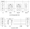
- 18 to 19 are diagrams for explaining an example in which a NAS message cannot be delivered after resuming of an S1-AP section fails, according to an embodiment.
- operation may be performed as follows.
- the eNB receives the S1-AP UE Context Resume Failure (step 2)
- the eNB releases the RRC connection, all signaling and data transport resources (step 3).
- the eNB cannot transmit the NAS message.
- the eNB cannot transmit an initial UE message including a NAS message to the MME (step 4).
- the NAS message is not delivered to the MME and the MME fails to deliver the NAS to the eNB even if a NAS rejection occurs for the UE (step 5).
- 'X' in the figure indicates that the procedure (steps 4 and 5) is not performed.
- a NAS rejection situation may occur in an MME.
- the eNB performs the release procedure (step 3) when the MME delivers the S1-AP UE Context Resume Failure (step 2), the NAS rejection message cannot be delivered (step 4).
- 'X' in the figure indicates that the procedure (step 4) is not performed.
- Rejection for the S1-AP message Rejection for the S1-AP message transmitted by the eNB, when the UE uses the user plane EPS optimization, the S1-AP message may be S1-AP Context Active.
- Rejection of NAS message (e.g. service request message): Rejection of NAS message (e.g. service request message) transmitted by the NAS layer of the UE.
- NAS message e.g. service request message
- the MME receives a NAS message (ie service request message)
- the cause of the rejection (situation)
- the cause of the UE receiving the rejection message It describes the operation.
- the above cases are described as 'S1-AP rejection' and 'NAS rejection', respectively.
- the UE uses user plain EPS optimization (or in EMM-Idle mode with suspend indicator) the UE does not send a service request message to the MME.
- the MME receives the S1-AP context active, a situation may arise where the conventional MME should reject the NAS message (e.g. denial of service).
- the MME transmits 'NAS rejection' to the UE.
- the MME does not receive a NAS message (ie service request message) from the UE, but rejects the NAS message If this occurs, we propose an operation to efficiently perform 'NAS rejection'.
- the MME If a situation in which a NAS message is rejected even when the NAS message is received from the UE occurs, it can be applied to the case of operating to efficiently perform the 'NAS rejection'.
- the MME sends the UE through S1-AP Context Active sent by the eNB.
- the request is acknowledged.
- the MME transmits the 'S1-AP rejection' after receiving the S1-AP Context Active, it also proposes a method for transmitting the 'NAS rejection'.
- the eNB may deliver the cause of the NAS rejection to the UE through a transmission S1-AP message and radio signaling (RRC message).
- RRC message radio signaling
- the MME identifies the cause of the denial of service situation that is appropriate for the situation, as usual. Thereafter, the S1-AP message includes an IE (i.e. cause, T3446 timer) for NAS rejection. At this time, the MME may operate as follows to transmit it to the eNB.
- an IE i.e. cause, T3446 timer
- the S1-AP UE Context Active ack may be indicated by instructing the rejection of the S1-AP UE Context Active.
- the S1-AP UE Context Active ack includes 'IE (ie cause, T3446 timer) for NAS rejection' to the eNB or a separate S1-AP message (eg Downlink).
- a NAS transport message or a new S1-AP message) is transmitted to the eNB including the IE (ie cause, T3446 timer) for NAS rejection.
- a new UE Context Active Failure message may be defined, and a relevant cause value for delivering an IE for 'NAS rejection' may be defined.
- the eNB transmits the 'NAS rejection IE (i.e. cause, T3446 timer)' in the RRC message to the AS layer of the UE.
- the RRC message may be an RRC connection release message.
- the RRC connection release message may be transmitted including a separate cause (e.g. release of the NAS signaling connection) indicating that the NAS signaling connection is released.
- the RRC message may be a new RRC message or a conventional RRCConnectionReconfiguration / DLInformationTransfer message.
- an RRC procedure for transmitting an RRC message including a NAS PDU may be performed separately from the RRC connection release procedure.
- the AS layer of the UE When the AS layer of the UE receives the RRC message transmitted in step 2, it may operate as follows. The following A and B may be performed together or one of them may be performed first. (A) The received 'NAS rejection IE (i.e. cause, T3446 timer)' is transmitted to the NAS layer of the UE. (B) transmit to the NAS layer with the cause of receiving the 'release of the NAS signaling connection'.
- a and B may be performed together or one of them may be performed first.
- the received 'NAS rejection IE i.e. cause, T3446 timer
- the NAS layer of the UE which has received this, may operate as if it receives a 'NAS Rejection IE (i.e. cause, T3446 timer)' along with the denial of service message in step (A).
- Step 4 (B) can be operated as in the prior art.
- FIG. 20 illustrates a case in which resumption fails in the S1-AP section according to an embodiment.
- NAS procedure of UE in EMM-IDLE mode with suspend indication is triggered with a suspend indication.
- the NAS message is generated other than the service request message (e.g. extended service request or TAU request message).
- the NAS layer holds the corresponding NAS message and delivers an RRC establishment cause and a call type to the AS layer.
- the AS layer receiving this performs a RACH procedure and, if successful, performs a resume procedure.
- the AS layer informs the NAS layer.
- the NAS layer receiving this sends the pending NAS message to the AS layer.
- the AS layer receiving this encapsulates the NAS message in RA msg5 and transmits it to the eNB.
- the eNB sends an S1-AP UE Context Resume Request message to the MME.
- the NAS reject cause may also be transmitted in a S1-AP UE context resume failure message.
- the eNB discards the NAS message received in step 2.
- the eNB forwards the NAS rejection to the UE-AS layer.
- the method can be implemented in one of two ways. For example, when using the RRC connection release: eNB performs the release procedure due to the S1-AP UE context resume failure message received in step 4, and transmits to the UE-AS layer including the NAS rejection cause in the RRC connection release message . As another example, when using the RRCConnectionReconfiguration or DLInformationTransfer message or the New RRC message: The eNB transmits the NAS rejection cause to the UE-AS layer including the NAS rejection cause in the RRC message and then receives the S1-AP UE context received in step 4. Perform release procedure due to resume failure message.
- the UE-AS layer delivers to the UE-NAS layer which is the cause of NAS rejection.
- the UE-NAS layer may recognize the NAS rejection and the reason thereof.
- FIG. 21 illustrates a case in which resumption fails in the S1-AP section according to another embodiment.
- the NAS procedure of the UE in EMM-IDLE mode with suspend indication is triggered with a suspend indication. At this time, a NAS message has generated a service request message.
- the NAS layer holds the corresponding NAS message and delivers an RRC establishment cause and a call type to the AS layer.
- the AS layer which has received this, performs the RACH procedure and, if successful, performs the resume procedure.
- the AS layer informs the NAS layer.
- the AS layer transmits RA msg5 to the eNB.
- the eNB sends an S1-AP UE Context Resume Request message to the MME.
- the NAS reject cause may also be transmitted in a S1-AP UE context resume failure message.
- the eNB forwards the corresponding NAS rejection to the UE-AS layer.
- the method can be implemented in one of two ways. For example, when using the RRC connection release: eNB performs the release procedure due to the S1-AP UE context resume failure message received in step 4, and transmits to the UE-AS layer including the NAS rejection cause in the RRC connection release message . As another example, when using the RRCConnectionReconfiguration or DLInformationTransfer message or the New RRC message: The eNB transmits the NAS rejection cause to the UE-AS layer including the NAS rejection cause in the RRC message and then receives the S1-AP UE context received in step 4. Perform release procedure due to resume failure message.
- the UE-AS layer delivers to the UE-NAS layer which will cause the NAS rejection.
- the UE-NAS layer may recognize the NAS rejection and the reason thereof.
- FIG. 22 is a diagram illustrating a configuration of a node device applied to the proposal of the present invention.
- the UE device 100 may include a transceiver 110, a processor 120, and a memory 130.
- the transceiver 110 may also be referred to as a radio frequency (RF) unit.
- the transceiver 110 may be configured to transmit various signals, data, and information to an external device, and receive various signals, data, and information to an external device. Alternatively, the transceiver 110 may be implemented by being separated into a transmitter and a receiver.
- the UE device 100 may be connected to the external device by wire and / or wirelessly.
- the processor 120 may control the overall operation of the UE device 100 and may be configured to perform a function of the UE device 100 to process and process information to be transmitted and received with an external device.
- the processor 120 may be configured to perform the UE operation proposed in the present invention.
- the processor 120 may control the transceiver 110 to transmit data or a message according to the proposal of the present invention.
- the memory 130 may store the processed information for a predetermined time and may be replaced with a component such as a buffer (not shown).
- the network node device 200 may include a transceiver 210, a processor 220, and a memory 230.
- the transceiver 210 may also be referred to as a radio frequency (RF) unit.
- the transceiver 210 may be configured to transmit various signals, data and information to an external device, and receive various signals, data and information to an external device.
- the network node device 200 may be connected to an external device by wire and / or wirelessly.
- the transceiver 210 may be implemented by being separated into a transmitter and a receiver.
- the processor 220 may control the overall operation of the network node device 200, and may be configured to perform a function of calculating and processing information to be transmitted / received with an external device.
- the processor 220 may be configured to perform the network node operation proposed in the present invention.
- the processor 220 may control the transceiver 110 to transmit data or a message to the UE or another network node according to the proposal of the present invention.
- the memory 230 may store the processed information for a predetermined time and may be replaced with a component such as a buffer (not shown).
- the specific configuration of the UE device 100 and the network device 200 as described above may be implemented such that the details described in the various embodiments of the present invention described above are applied independently or two or more embodiments are applied at the same time, overlapping The description is omitted for clarity.
- Embodiments of the present invention described above may be implemented through various means.
- embodiments of the present invention may be implemented by hardware, firmware, software, or a combination thereof.
- a method according to embodiments of the present invention may include one or more Application Specific Integrated Circuits (ASICs), Digital Signal Processors (DSPs), Digital Signal Processing Devices (DSPDs), and Programmable Logic Devices (PLDs). It may be implemented by field programmable gate arrays (FPGAs), processors, controllers, microcontrollers, microprocessors, and the like.
- ASICs Application Specific Integrated Circuits
- DSPs Digital Signal Processors
- DSPDs Digital Signal Processing Devices
- PLDs Programmable Logic Devices
- FPGAs field programmable gate arrays
- processors controllers, microcontrollers, microprocessors, and the like.
- the method according to the embodiments of the present invention may be implemented in the form of an apparatus, procedure, or function for performing the functions or operations described above.
- the software code may be stored in a memory unit and driven by a processor.
- the memory unit may be located inside or outside the processor, and may exchange data with the processor by various known means.
- the above-described communication method can be applied not only to 3GPP systems but also to various wireless communication systems including IEEE 802.16x and 802.11x systems. Furthermore, the proposed method can be applied to mmWave communication system using ultra high frequency band.
Landscapes
- Engineering & Computer Science (AREA)
- Computer Networks & Wireless Communication (AREA)
- Signal Processing (AREA)
- Mobile Radio Communication Systems (AREA)
Abstract
La présente invention concerne un procédé permettant de réaliser de manière efficace un rejet de strate non d'accès (NAS pour Non-Access Stratum) lors de la réalisation d'une reprise de connexion de commande de ressources radio (RRC pour Radio Resource Control) dans un système de communication sans fil. Un procédé permettant de réaliser, au moyen d'une station de base, une reprise de connexion de commande de ressources radio (RRC) dans un système de communication sans fil peut comprendre les étapes consistant : à réaliser une procédure de reprise de connexion de commande RRC avec un équipement utilisateur (UE pour User Equipment) ; à transmettre un message de demande de reprise à une entité de gestion de Mobilité (MME pour Mobile Management Entity) ; et à recevoir un message d'échec de reprise comportant une cause de rejet de strate NAS en provenance de l'entité MME lorsque la demande de reprise n'a pas été autorisée.
Priority Applications (1)
| Application Number | Priority Date | Filing Date | Title |
|---|---|---|---|
| US16/075,112 US10681767B2 (en) | 2016-02-05 | 2017-02-06 | Method and apparatus for performing RRC connection resume in wireless communication system |
Applications Claiming Priority (4)
| Application Number | Priority Date | Filing Date | Title |
|---|---|---|---|
| US201662292200P | 2016-02-05 | 2016-02-05 | |
| US62/292,200 | 2016-02-05 | ||
| US201662335634P | 2016-05-12 | 2016-05-12 | |
| US62/335,634 | 2016-05-12 |
Publications (1)
| Publication Number | Publication Date |
|---|---|
| WO2017135779A1 true WO2017135779A1 (fr) | 2017-08-10 |
Family
ID=59500427
Family Applications (1)
| Application Number | Title | Priority Date | Filing Date |
|---|---|---|---|
| PCT/KR2017/001269 Ceased WO2017135779A1 (fr) | 2016-02-05 | 2017-02-06 | Procédé et appareil permettant de réaliser une reprise de connexion rrc dans un système de communication sans fil |
Country Status (2)
| Country | Link |
|---|---|
| US (1) | US10681767B2 (fr) |
| WO (1) | WO2017135779A1 (fr) |
Cited By (4)
| Publication number | Priority date | Publication date | Assignee | Title |
|---|---|---|---|---|
| CN110301163A (zh) * | 2017-08-11 | 2019-10-01 | 联发科技股份有限公司 | 用于物联网的用户设备自动释放 |
| CN110831261A (zh) * | 2018-08-10 | 2020-02-21 | 诺基亚技术有限公司 | 组合的rrc非活动恢复、rrc rna&nas注册过程 |
| CN112534958A (zh) * | 2018-08-09 | 2021-03-19 | 谷歌有限责任公司 | 小区重选后恢复失败处置 |
| CN112740824A (zh) * | 2018-09-25 | 2021-04-30 | 瑞典爱立信有限公司 | 恢复请求随后释放和重定向 |
Families Citing this family (15)
| Publication number | Priority date | Publication date | Assignee | Title |
|---|---|---|---|---|
| CN107046735B (zh) * | 2016-02-05 | 2020-07-28 | 中兴通讯股份有限公司 | 终端与网络间连接处理方法和装置 |
| US10687202B2 (en) * | 2016-03-09 | 2020-06-16 | Lg Electronics Inc. | Method and device for configuring bearer for transmission of user data |
| GB2548878A (en) * | 2016-03-31 | 2017-10-04 | Nec Corp | Communication system |
| EP3443808A1 (fr) * | 2016-04-11 | 2019-02-20 | Telefonaktiebolaget LM Ericsson (PUBL) | Procédé et premier noeud pour découpler un sctp et un s1ap |
| CN107318176B (zh) * | 2016-04-26 | 2022-12-20 | 中兴通讯股份有限公司 | 恢复标识的获取、发送方法及装置、ue、接入网设备 |
| WO2017195718A1 (fr) | 2016-05-13 | 2017-11-16 | 京セラ株式会社 | Terminal sans fil |
| CN113038633A (zh) * | 2016-05-18 | 2021-06-25 | 瑞典爱立信有限公司 | 操作无线通信网络的节点的方法和相关的节点 |
| US20180049120A1 (en) * | 2016-08-09 | 2018-02-15 | Nokia Solutions And Networks Oy | Network signaling optimization for light connected mode |
| EP3806575A1 (fr) * | 2017-01-16 | 2021-04-14 | Telefonaktiebolaget Lm Ericsson (Publ) | Mise à jour de zone de suivi dans rrc_inactif |
| RU2749090C1 (ru) * | 2018-01-18 | 2021-06-04 | Телефонактиеболагет Лм Эрикссон (Пабл) | Способы и устройства для определения категорий доступа и/или причин установления |
| DK3624549T3 (da) * | 2018-04-02 | 2021-05-03 | Guangdong Oppo Mobile Telecommunications Corp Ltd | Fremgangsmåder og anordninger til kontrol af rrc-tilstand |
| EP3570627B1 (fr) * | 2018-05-09 | 2024-01-17 | HTC Corporation | Dispositif de gestion d'une cause de reprise dans un message de commande de ressource radio |
| WO2020025556A1 (fr) * | 2018-08-03 | 2020-02-06 | Telefonaktiebolaget Lm Ericsson (Publ) | Optimisations de plan utilisateur pour l'internet des objets cellulaire 5g |
| CN115669207B (zh) * | 2020-07-10 | 2026-03-06 | Oppo广东移动通信有限公司 | 建立mbs业务的方法及装置、终端设备、网络设备 |
| CN116548022A (zh) * | 2020-10-01 | 2023-08-04 | 瑞典爱立信有限公司 | 用于网络功能发现和选择的方法和设备 |
Citations (5)
| Publication number | Priority date | Publication date | Assignee | Title |
|---|---|---|---|---|
| WO2009075341A1 (fr) * | 2007-12-13 | 2009-06-18 | Nec Corporation | Reprise sur incident de liaison radio |
| US20130039339A1 (en) * | 2011-08-12 | 2013-02-14 | Venkata Ratnakar Rao Rayavarapu | Other Network Component Receiving RRC Configuration Information from eNB |
| WO2013107391A1 (fr) * | 2012-01-18 | 2013-07-25 | Mediatek Inc. | Procédé de restauration de connexion améliorée et de restauration de données sans perte |
| EP2645804A1 (fr) * | 2012-03-27 | 2013-10-02 | BlackBerry Limited | Rétablissement d'une connexion RRC suspendue à un ENB différent |
| US8768305B1 (en) * | 2012-10-09 | 2014-07-01 | Sprint Communications Company L.P. | Reestablishing a mobile device radio resource control connection |
Family Cites Families (3)
| Publication number | Priority date | Publication date | Assignee | Title |
|---|---|---|---|---|
| US9826404B2 (en) * | 2011-01-11 | 2017-11-21 | Qualcomm Incorporated | System and method for peer-to-peer authorization via non-access stratum procedures |
| US9609602B2 (en) * | 2012-09-28 | 2017-03-28 | Intel Corporation | Always-on bearer for small data transfers in LTE systems |
| CN107041017A (zh) * | 2016-02-04 | 2017-08-11 | 中兴通讯股份有限公司 | Ue上下文信息恢复方法、装置和系统 |
-
2017
- 2017-02-06 WO PCT/KR2017/001269 patent/WO2017135779A1/fr not_active Ceased
- 2017-02-06 US US16/075,112 patent/US10681767B2/en active Active
Patent Citations (5)
| Publication number | Priority date | Publication date | Assignee | Title |
|---|---|---|---|---|
| WO2009075341A1 (fr) * | 2007-12-13 | 2009-06-18 | Nec Corporation | Reprise sur incident de liaison radio |
| US20130039339A1 (en) * | 2011-08-12 | 2013-02-14 | Venkata Ratnakar Rao Rayavarapu | Other Network Component Receiving RRC Configuration Information from eNB |
| WO2013107391A1 (fr) * | 2012-01-18 | 2013-07-25 | Mediatek Inc. | Procédé de restauration de connexion améliorée et de restauration de données sans perte |
| EP2645804A1 (fr) * | 2012-03-27 | 2013-10-02 | BlackBerry Limited | Rétablissement d'une connexion RRC suspendue à un ENB différent |
| US8768305B1 (en) * | 2012-10-09 | 2014-07-01 | Sprint Communications Company L.P. | Reestablishing a mobile device radio resource control connection |
Cited By (8)
| Publication number | Priority date | Publication date | Assignee | Title |
|---|---|---|---|---|
| CN110301163A (zh) * | 2017-08-11 | 2019-10-01 | 联发科技股份有限公司 | 用于物联网的用户设备自动释放 |
| CN112534958A (zh) * | 2018-08-09 | 2021-03-19 | 谷歌有限责任公司 | 小区重选后恢复失败处置 |
| CN110831261A (zh) * | 2018-08-10 | 2020-02-21 | 诺基亚技术有限公司 | 组合的rrc非活动恢复、rrc rna&nas注册过程 |
| CN110831261B (zh) * | 2018-08-10 | 2023-06-23 | 诺基亚技术有限公司 | 用于组合的rrc非活动恢复、rrc rna&nas注册过程的装置 |
| CN112740824A (zh) * | 2018-09-25 | 2021-04-30 | 瑞典爱立信有限公司 | 恢复请求随后释放和重定向 |
| US11924693B2 (en) | 2018-09-25 | 2024-03-05 | Telefonaktiebolaget Lm Ericsson (Publ) | Resume request followed by release and redirect |
| US11937131B2 (en) | 2018-09-25 | 2024-03-19 | Telefonaktiebolaget Lm Ericsson (Publ) | Resume request followed by release and redirect |
| CN112740824B (zh) * | 2018-09-25 | 2024-06-04 | 瑞典爱立信有限公司 | 恢复请求随后释放和重定向 |
Also Published As
| Publication number | Publication date |
|---|---|
| US20190045572A1 (en) | 2019-02-07 |
| US10681767B2 (en) | 2020-06-09 |
Similar Documents
| Publication | Publication Date | Title |
|---|---|---|
| WO2017142363A1 (fr) | Transmission de demande de service et équipement d'utilisateur, et réception de requête de service et station de base | |
| WO2017126928A1 (fr) | Procédé de changement de mode de connexion et entité de gestion de mobilité | |
| WO2018231007A1 (fr) | Procédé permettant de répondre à une demande et dispositif de réseau | |
| WO2018169343A1 (fr) | Procédé et station de base pour effectuer une radiomessagerie, et procédé et entité de réseau pour prendre en charge une radiomessagerie | |
| WO2017119778A1 (fr) | Dispositif d'utilisateur et procédé d'émission de données associé, et nœud de réseau et procédé d'émission de données associé | |
| WO2017126942A1 (fr) | Procédé et équipement utilisateur permettant de recevoir des données, et procédé et station de base permettant de transmettre des données | |
| WO2017164674A1 (fr) | Procédé pour changer un mode de connexion dans une station de base, et station de base associée, et procédé pour changer un mode de connexion dans un équipement utilisateur, et équipement utilisateur associé | |
| WO2018088812A1 (fr) | Procédé et équipement utilisateur de transfert intercellulaire | |
| WO2018128519A1 (fr) | Procédé par lequel un ue relais ayant une connexion avec un ue distant connecte un réseau dans un système de communication sans fil et appareil associé | |
| WO2018155934A1 (fr) | Procédé de réception de données relatives à un accès non-3gpp par l'intermédiaire d'un accès 3gpp dans un système de communication sans fil, et dispositif associé | |
| WO2014112826A1 (fr) | Procédé et terminal permettant de déterminer un transfert pour le trafic déchargé sur un wlan | |
| WO2017146523A1 (fr) | Procédé et équipement utilisateur de requête de connexion à un réseau | |
| WO2018230928A1 (fr) | Procédé et appareil de signalement d'informations d'emplacement d'un équipement utilisateur dans un système de communications sans fil | |
| WO2018199611A1 (fr) | Procédé et équipement utilisateur permettant de transmettre une demande d'enregistrement à un réseau, et procédé et dispositif de réseau permettant de recevoir une demande d'enregistrement | |
| WO2018080230A1 (fr) | Procédé de détermination de mode d'emm dans un système de communication sans fil, et appareil pour cela | |
| WO2018066919A1 (fr) | Procédé de connexion à un réseau et équipement utilisateur | |
| WO2014058244A1 (fr) | Procédé de traitement de message de recherche et procédé de relais de données de liaison descendante | |
| WO2018169244A1 (fr) | Procédé de notification d'événement de mobilité dans un système de communication sans fil et dispositif correspondant | |
| WO2017099464A1 (fr) | Procédé de commande de libération de connexion s1 par un objet de gestion de mobilité, objet de gestion de mobilité, procédé de commande de libération de connexion s1 par une station de base, et station de base | |
| WO2018026185A1 (fr) | Procédé d'essayage de connexion et équipement utilisateur, et procédé de commande de connexion et station de base | |
| WO2016208997A1 (fr) | Procédé pour gérer une zone d'un terminal dans un système de communication sans fil et appareil associé | |
| WO2017105077A1 (fr) | Équipement utilisateur et procédé de réception de données, et nœud de réseau et procédé de transmission de données | |
| WO2017188758A1 (fr) | Procédé et appareil d'interruption/reprise de signalisation nas dans un système de communication sans fil | |
| WO2016111590A1 (fr) | Procédé pour la transmission de radiomessagerie dans un système de communication sans fil et dispositif associé | |
| WO2017074012A1 (fr) | Procédé de communication directe entre des terminaux dans un système de communication sans fil et dispositif associé |
Legal Events
| Date | Code | Title | Description |
|---|---|---|---|
| 121 | Ep: the epo has been informed by wipo that ep was designated in this application |
Ref document number: 17747822 Country of ref document: EP Kind code of ref document: A1 |
|
| NENP | Non-entry into the national phase |
Ref country code: DE |
|
| 122 | Ep: pct application non-entry in european phase |
Ref document number: 17747822 Country of ref document: EP Kind code of ref document: A1 |