WO2017138054A1 - 水耕栽培装置 - Google Patents
水耕栽培装置 Download PDFInfo
- Publication number
- WO2017138054A1 WO2017138054A1 PCT/JP2016/005091 JP2016005091W WO2017138054A1 WO 2017138054 A1 WO2017138054 A1 WO 2017138054A1 JP 2016005091 W JP2016005091 W JP 2016005091W WO 2017138054 A1 WO2017138054 A1 WO 2017138054A1
- Authority
- WO
- WIPO (PCT)
- Prior art keywords
- plant
- light
- door
- cultivation tank
- light shielding
- Prior art date
- Legal status (The legal status is an assumption and is not a legal conclusion. Google has not performed a legal analysis and makes no representation as to the accuracy of the status listed.)
- Ceased
Links
Images


Classifications
-
- A—HUMAN NECESSITIES
- A01—AGRICULTURE; FORESTRY; ANIMAL HUSBANDRY; HUNTING; TRAPPING; FISHING
- A01G—HORTICULTURE; CULTIVATION OF VEGETABLES, FLOWERS, RICE, FRUIT, VINES, HOPS OR SEAWEED; FORESTRY; WATERING
- A01G31/00—Soilless cultivation, e.g. hydroponics
- A01G31/02—Special apparatus therefor
-
- Y—GENERAL TAGGING OF NEW TECHNOLOGICAL DEVELOPMENTS; GENERAL TAGGING OF CROSS-SECTIONAL TECHNOLOGIES SPANNING OVER SEVERAL SECTIONS OF THE IPC; TECHNICAL SUBJECTS COVERED BY FORMER USPC CROSS-REFERENCE ART COLLECTIONS [XRACs] AND DIGESTS
- Y02—TECHNOLOGIES OR APPLICATIONS FOR MITIGATION OR ADAPTATION AGAINST CLIMATE CHANGE
- Y02P—CLIMATE CHANGE MITIGATION TECHNOLOGIES IN THE PRODUCTION OR PROCESSING OF GOODS
- Y02P60/00—Technologies relating to agriculture, livestock or agroalimentary industries
- Y02P60/20—Reduction of greenhouse gas [GHG] emissions in agriculture, e.g. CO2
- Y02P60/21—Dinitrogen oxide [N2O], e.g. using aquaponics, hydroponics or efficiency measures
Definitions
- the present invention relates to a hydroponic cultivation apparatus that cultivates plants without using soil.
- a partition unit that partitions an above-ground space in which the above-ground part of the plant grows and an underground space in which the below-ground part of the plant grows in the cultivation tank is provided. Is provided.
- the light source is provided in the ground space. Therefore, the light emitted from the light source is applied to the ground part of the plant, but is blocked by the partition part. As a result, the light emitted from the light source does not reach the underground part of the plant.
- the partition part in order to observe the underground part of the plant after installing the partition member in the cultivation tank, the partition part must be removed from the cultivation tank. Therefore, the work for observing the underground part of the plant becomes complicated.
- the present invention has been made in view of such problems of the conventional technology. And the objective of this invention is providing the hydroponic cultivation apparatus which can perform the operation
- a hydroponic cultivation apparatus covers a light-shielding cultivation tank configured to accommodate an underground portion of a plant and an opening at the upper end of the cultivation tank.
- a light-shielding partition that partitions an underground space in which the plant's underground part grows and an above-ground space in which the plant's above-ground part grows, and the partition part is fixed in position relative to the cultivation tank.
- a fixing member that has a through hole that surrounds the stem of the plant, maintains a closed state that suppresses light from being irradiated to the underground portion of the plant, and the movable member is movable with respect to the fixing member.
- a door member that is attached to a fixing member and changes between a closed state that suppresses light from being irradiated to the underground portion of the plant and an open state that allows the underground portion of the plant to be visually recognized.
- the work of observing the underground part of a plant can be easily performed.
- the hydroponic cultivation apparatus includes a light-shielding partition 50.
- the partition part 50 is for preventing light from reaching the underground part of the plant, as will be described in detail later.
- the partition portion 50 includes a fixing member 123 and a door member 4.
- the fixing member 123 is indirectly fixed to a cultivation tank, which will be described later, via a support portion 70 (see FIG. 2), which will be described later.
- the door member 4 is attached to the fixed member 123 so as to be movable with respect to the fixed member 123, as will be described later.
- the fixing member 123 includes a plate member 1, a plate member 2 adjacent to the plate member 1, and a plate member 3 adjacent to the plate member 2.
- the door member 4 is a plate member adjacent to the plate member 3.
- the plate-like member 1 has two through holes 1X penetrating in the thickness direction, and two semicircular cutouts 1A formed on the end surface adjacent to the plate-like member 2. Screws described later are inserted into the two through holes 1X. An arcuate elastic member 5 is attached to the notch 1A.
- the plate-like member 2 has two through holes 2X penetrating in the thickness direction. Screws described later are inserted into the two through holes 2X.
- the plate-like member 2 includes two semicircular cutouts 2A formed on an end surface adjacent to the plate-like member 1 and two semicircular cutouts 2B formed on an end surface adjacent to the plate-like member 3. Have.
- the semicircular cutout 1A of the plate-like member 1 and the semicircular cutout 2A of the plate-like member 2 are integrally formed to form one circular through hole.
- Arc-shaped elastic members 5 are attached to the notches 2A and 2B, respectively.
- the plate-like member 3 is formed with two through holes 3X penetrating in the thickness direction. Screws described later are inserted into the two through holes 3X.
- the plate-like member 3 has two semicircular cutouts 3 ⁇ / b> A formed on the end surface adjacent to the plate-like member 2.
- the semicircular cutout 2B of the plate-like member 2 and the semicircular cutout 3A of the plate-like member 3 are integrally formed to form one circular through hole.
- An arcuate elastic member 5 is attached to the notch 3A.
- four screw holes 3 ⁇ / b> C are formed in the plate-like member 3. Screws described later are screwed into the four screw holes 3C.
- the plate-like member 1 and the plate-like member 2 adjacent thereto have a pair of notches 1A and 2A on a pair of opposed surfaces facing each other.
- the plate-like member 2 and the plate-like member 3 adjacent thereto have a pair of notches 2B and 3A on a pair of opposed surfaces facing each other.
- the pair of notches are integrated to form the aforementioned through hole.
- the door member 4 is formed with two through holes 4X and four screw holes 4C penetrating in the thickness direction.
- a temporary fixing screw which will be described later, is inserted into the two through holes 4X. Screws described later are screwed into the four screw holes 4C.
- the door member 4 constitutes a plate-like member at the outermost side, that is, an end portion of a plurality of plate-like members provided side by side along one direction.
- the aforementioned elastic member 5 is elastically deformed according to the shape of the plant stem.
- Each of the plurality of elastic members 5 is preferably a member having flexibility, and is preferably a member such as urethane sponge (urethane foam) or rubber sponge.
- the elastic member 5 is preferably black that absorbs light.
- the two elastic members 5 facing each other cooperate with each other while elastically deforming, and close the gap between each of the notches 1A, 2A, 2B, 3A, 3B and the stem as the ground portion 11. . Therefore, the gap between the opening and the stem can be closed simultaneously with the installation of the partition portion 50.
- the partition part 50 is for suppressing the arrival of light to the underground part 12, it is desirable to have a color that absorbs light such as black. Even if there is a small gap between the plate-like members 1, 2, 3 or between the plate-like member 3 and the door member 4, since black absorbs light, the underground space is maintained in a dark state. be able to.
- the notches of the plate-like members facing each other of the partition portion 50 form a circular opening through which the plant stem penetrates.
- the notch constituting the opening through which the plant stem penetrates may be provided only in one plate-like member.
- the shape of the opening may not be circular as long as the stem of the plant 10 is not damaged.
- the diameter of a circular opening formed by a pair of semicircular notches is about 4 cm, it may be suitable for bundling about four stems.
- the gap between the circular opening and the stem covers the entire partition 50, but may be covered with a flexible light-shielding sheet having a hole through which only a plurality of stems penetrates.
- the hydroponic cultivation apparatus 100 includes a cultivation tank 80.
- the cultivation tank 80 includes a support part 70 for supporting the partition part 50 described above.
- the support part 70 includes four column parts 72 extending in the vertical direction from the inner sides of the four corners of the cultivation tank 80.
- the support part 70 includes four rectangular frame parts 71. The four corners of the rectangular frame 71 are fixed to the upper ends of the four pillars 72, respectively.
- the plate-like member 1 is placed on the frame portion 71.
- the frame portion 71 is formed with a through hole 71A penetrating in the thickness direction. Between the frame portion 71 and the cultivation tank 80, there is a gap serving as an air flow path 20 for communicating the internal space of the cultivation tank 80 and the external space of the cultivation tank 80.
- the underground portion 12 of the plant 10 is positioned on the wire mesh 9 so that the stem of the plant 10 contacts the arc-shaped elastic member 5.
- the ground part 11 of the plant 10 protrudes upward from the partition part 50.
- a gap is drawn between the stem of the plant 10 and the elastic member 5, but there is no gap between the stem of the plant 10 and the elastic member 5. Good.
- the cultivation tank 80 accommodates the underground part 12 of the plant 10.
- a wire mesh 9 is provided in the cultivation tank 80.
- An underground portion 12 of the plant 10 is placed on the wire mesh 9.
- the wire mesh 9 is fixed to the four column portions 72.
- a root 13 extending from the underground portion 12 of the plant 10 penetrates the mesh of the wire mesh 9 and is immersed in a nutrient solution 81 stored at the bottom of the cultivation tank 80 below the wire mesh 9.
- the plant 10 absorbs the nutrient solution 81 from the root 13 and grows.
- the plate-like member 2, the plate-like member 3, and the door member 4 are placed on the support portion 70. Thereafter, the eight screws 61 are screwed into the four screw holes 3C and the four screw holes 4C shown in FIG. Thereby, the two hinges 60 are fixed to the plate-like member 3 and the door member 4 by the eight screws 61. Therefore, the door member 4 is rotatable around a rotation axis common to the two hinges 60. That is, the door member 4 is in a state that can be opened or closed.
- the hydroponic cultivation apparatus 100 includes a light shielding member 51.
- the light shielding member 51 includes a fixed light shielding member 51B and a door light shielding member 51A.
- the fixed light shielding member 51B is formed with through holes 51B1, 51B2, 51B3 penetrating in the thickness direction.
- a through-hole 51A4 penetrating in the thickness direction is formed in the door light-shielding member 51A.
- the partition 50 is provided at a position above the cultivation tank 80 so as to cover the opening at the upper end of the cultivation tank 80.
- a light shielding member 51 is fixed to the partition portion 50.
- the light shielding member 51 is formed by integrating the fixed light shielding member 51B and the door light shielding member 51A.
- the light shielding member 51 constitutes a frame-like member that surrounds the four side surfaces of the cultivation tank 80 in a plan view, and in a cross-sectional view, as inferred from FIG. 5.
- a curtain-like member that covers the upper part of the side surface of the tank 80 is formed.
- each of the six screws 6 includes six through holes 51B1, 51B2, 51B3 of the fixed light shielding member 51B, and six through holes 1X, 2X of the plate-like members 1, 2, 3 corresponding thereto. , 3X.
- the above-described six screws 6 are inserted into the six through holes 71A of the frame portion 71 corresponding to the six through holes 1X, 2X, and 3X of the plate-like members 1, 2, and 3, respectively. Thereafter, the six screws 6 are respectively screwed to female screw portions (not shown) formed in the six through holes 71A. According to this, the position of plate-shaped member 1,2,3 with respect to the cultivation tank 80 can be fixed. Therefore, damage to the stem of the plant 10 due to the movement of the partition 50 can be suppressed.
- the two screws 6 for temporary fixing are respectively inserted into the two through holes 51A4 of the door light shielding member 51A and the two through holes 4X of the door member 4 corresponding thereto. Also, the two screws 6 for temporary fixing are respectively inserted into the two through holes 4X of the door member 4 and the two through holes 71A of the frame portion 71 corresponding to them.
- the through hole 71A of the frame portion 71 corresponding to the through hole 4X of the door member 4 does not have a female screw portion. Therefore, the above-described two screws 6 for temporary fixing are not screwed, and thus move together with the door member 4 along with the opening / closing operation of the door member 4.
- the light shielding member 7 is provided on the partition portion 50.
- the six light shielding members 7 are provided so as to straddle two adjacent plate-like members among the plate-like members 1, 2, and 3.
- the other three light shielding members 7 are provided so as to straddle the plate-like member 3 and the door member 4.
- the light shielding member 7 covers each of the gap between the plate-like members 1, 2, 3 and the gap between the plate-like member 3 and the door member 4. According to this, it can suppress that light approachs into the cultivation tank 80 from the clearance gap between plate-shaped members 1, 2, and 3 and the clearance gap between the plate-shaped member 3 and the door member 4.
- the light shielding member 7 may be affixed to the plate-like members 1, 2, 3 like an adhesive tape.
- the light shielding member 7 may be a light shielding multi-sheet that is generally used in agriculture and attached with an adhesive.
- the light shielding member 7 may be a plastic sheet.
- the light shielding member 7 preferably has a black color from the viewpoint of light absorption.
- the hydroponic cultivation apparatus 100 is provided in a housing 90 provided with a door through which a grower of the plant 10 can enter and exit.
- An illumination unit 30 is provided in the housing 90.
- the leaves When the leaves are formed on the ground part 11 of the plant 10, the leaves perform photosynthesis with the light emitted from the illumination unit 30.
- the root 13 extending from the underground portion 12 of the plant 10 passes through the mesh of the wire mesh 9 and is immersed in the nutrient solution 81. Therefore, the plant 10 can absorb the nutrient solution 81 from the root 13.
- the light shielding member 51 surrounds the outer surface of the cultivation tank 80 in a plan view, and the air flow path 20 extends downward along the outer surface of the cultivation tank 80. It hangs down from the outer periphery.
- the light shielding member 51 includes a fixed light shielding member 51B attached to the fixed member 123 and a door light shielding member 51A attached to the door member 4 and separated from the fixed light shielding member 51B.
- an air flow path 20 exists between the partition 50 and the cultivation tank 80.
- the outer periphery of the frame portion 71 is slightly larger than the outer periphery of the cultivation tank 80 in plan view. Therefore, the air flow path 20 also extends between the outer surface of the cultivation tank 80 and the portion of the light shielding member 51 extending in the vertical direction. Therefore, for example, as indicated by an arrow X, an air flow is generated along the air flow path 20 so that the atmosphere in the cultivation tank 80 and the external atmosphere are naturally switched.
- the air flow path 20 between the partition 50 and the cultivation tank 80 is covered with a light shielding member 51. Therefore, it is suppressed that the underground part 12 of the plant 10 in the cultivation tank 80 is irradiated with light.
- the light shielding member 51 of the cultivation tank 80 is provided.
- the entrance of light from the side to the inside of the cultivation tank 80 via the air flow path 20 is suppressed.
- the grower of the plant 10 can easily open the door member 4 together with the light shielding member 51 when visually recognizing the space in the cultivation tank 80.
- the support portion 70 has a frame structure, and the gap between the cultivation tank 80 and the frame portion 71 constitutes the air flow path 20.
- the hydroponics apparatus 100 does not need to have the support part 70, when the air flow path 20 is not required or when the cultivation tank 80 is provided with the opening for ventilation.
- each of the plate-like members 1, 2, 3 may be directly fixed to the upper end of the cultivation tank 80.
- the hydroponic cultivation apparatus 100 includes a fixing screw 6 that fixes the support portion 70, particularly the frame portion 71 and each of the plate-like members 1, 2, and 3.
- the support part 70 is fixed to the cultivation tank 80, and the plate-like members 1, 2, and 3 are indirectly fixed to the cultivation tank 80 with the support part 70 as a medium.
- the plate-like members 1, 2, 3 may be fixed to the support portion 70 by any material such as a nail, an adhesive, a cellophane tape, or a hook-and-loop fastener (magic tape (registered trademark)) instead of the screw 6. . According to this, the position of the plate-shaped members 1, 2, and 3 with respect to the cultivation tank 80 can be fixed. Therefore, damage to the stem of the plant 10 due to the movement of the partition 50 can be suppressed.
- the partition 50 partitions the ground space 11A in which the above-ground part 11 of the plant 10 grows and the underground space 12A in which the underground part 12 of the plant 10 grows.
- the partition part 50 includes the fixing member 123 and the door member 4 described above.
- the door member 4 is rotated around the rotation axis of the hinge 60 during cultivation of the plant 10 in the direction indicated by the arrow Y. Thereby, the door member 4 can be opened.
- the light shielding member 51 ⁇ / b> A for the door moves together with the door member 4 because it is attached to the door member 4 with the screws 6 for temporary fixing. Therefore, the grower of the plant 10 can visually recognize the state of the underground portion 12 of the plant 10 during the growth.
- the light shielding member 51 ⁇ / b> A for the door has a certain degree of hardness, and is drawn so that its shape does not change with the movement of the door member 4.
- the door light-shielding member 51 ⁇ / b> A is formed of a flexible sheet, cloth, vinyl, or the like, the shape of the door light-shielding member 51 ⁇ / b> A may change depending on the opening / closing operation of the door member 4.
- the fixing member 123 is fixed in position relative to the cultivation tank 80 and maintains a closed state in which light is prevented from entering the underground space 12A.
- the door member 4 is attached to the fixed member 123 so as to be movable with respect to the fixed member 123, and is in a closed state in which light is prevented from entering the underground space 12A and an open state in which the underground space 12A can be visually recognized.
- the door member 4 changes into a closed state where light is irradiated to the underground part 12 of the plant 10 and an open state where the underground part 12 of the plant 10 can be visually recognized.
- the grower of the plant 10 can visually recognize the underground portion 12 of the plant 10 in the space inside the cultivation tank 80 from above the cultivation tank 80 by opening the door member 4. That is, the underground part 12 in the cultivation tank 80 can be visually recognized by a simple operation of opening the door member 4. Moreover, if the door member 4 is in an open state, the underground portion 12 can be easily photographed.
- the light shielding member 7 is flexible enough to be bent along the rotation axis of the hinge 60 when the door member 4 is opened. Therefore, the light shielding member 7 does not hinder the opening / closing operation of the door member 4. Further, the light shielding member 7 is not destroyed by the opening / closing operation of the door member 4.
- the door member 4 constitutes an end portion of the partition portion 50. Therefore, the grower of the plant 10 can easily open the door member 4 without providing a handle on the door member 4.
- FIG. 9 a light shielding member 51 of a modification of the hydroponic cultivation apparatus 100 of the embodiment is fixed to a frame portion 71. That is, the light shielding member 51 is sandwiched between the partition portion 50 and the frame portion 71. In this case, the light shielding member 51 does not move together with the door member 4 and always covers the air flow path 20. In other words, only the door member 4 is opened or closed. Therefore, the door member 4 can be easily opened and closed. Further, the fixed light-shielding member 51B and the door light-shielding member 51A shown in FIG. 4 are not separated and may be integrally formed.
- the light shielding member 51 has the same shape as the overall shape shown in FIG. 4, it may be formed by assembling a series of thin plates or sewing a vinyl sheet. That is, also in the hydroponic cultivation apparatus 100 of the modified example, the light shielding member 51 surrounds the side surface of the cultivation tank 80 in a plan view, and partitions so that the air flow path 20 extends downward along the side surface of the cultivation tank 80. What is necessary is just to hang down from the outer periphery of the part 50. FIG. This also makes it possible to ventilate the underground space 12 ⁇ / b> A while suppressing light from entering the underground space 12 ⁇ / b> A via the air flow path 20. Furthermore, according to this modification, since the light shielding member 51 can be formed as one component, the light shielding member 51 can be more easily formed.
- the hydroponic cultivation apparatus 100 includes a light shielding cultivation tank 80 and a light shielding partition 50.
- the cultivation tank 80 is configured to accommodate the underground portion 12 of the plant 10.
- the light-shielding partition 50 is provided so as to cover the opening at the upper end of the cultivation tank 80, and partitions the underground space 12A in which the underground part 12 of the plant 10 grows and the ground space 11A in which the above-ground part 11 of the plant 10 grows.
- Partition 50 includes a fixing member 123 and a door member 4. The fixing member 123 is fixed in position relative to the cultivation tank 80, has a through hole surrounding the stem of the plant 10, and maintains a closed state that suppresses light from being irradiated to the underground portion 12 of the plant 10.
- the door member 4 is attached to the fixing member 123 so as to be movable with respect to the fixing member 123, and visually recognizes the closed state and the underground portion 12 of the plant 10 in which light is not applied to the underground portion 12 of the plant 10. Change to an open state.
- the grower of the plant 10 can visually recognize the underground portion 12 of the plant 10 in the space inside the cultivation tank 80 from above the cultivation tank 80 by opening the door member 4.
- the door member 4 may be a hinged door that is attached to the fixing member 123 with the hinge 60 as a medium, and that can rotate around the rotation axis of the hinge 60 with respect to the fixing member 123.
- the hydroponic cultivation apparatus 100 further includes a light shielding member 7.
- the light shielding member 7 is provided so as to cover the gap between the door member 4 and the fixing member 123, and is bent along the rotation axis of the hinge 60 when the door member 4 is opened.
- the door member 4 constitutes an end portion of the partition portion 50. According to this, even if a handle is not provided in the door member 4, the door member 4 can be opened easily.
- the hydroponic cultivation apparatus 100 may further include a support unit 70 and a light shielding member 51.
- the support part 70 is installed in the cultivation tank 80, and the partition part is located above the upper end part of the cultivation tank 80 so that the air flow path 20 is formed between the cultivation tank 80 and the partition part 50. 50 is supported.
- the light shielding member 51 surrounds the side surface of the cultivation tank 80 in plan view and hangs down from the outer periphery of the partition portion 50 so that the air flow path 20 extends downward along the side surface of the cultivation tank 80.
- the light shielding member 51 includes a fixed light shielding member 51B attached to the fixed member 123 and a door light shielding member 51A attached to the door member 4 and separated from the fixed light shielding member 51B.
- the light shielding member 51 of the cultivation tank 80 is provided.
- the entrance of light from the side to the inside of the cultivation tank 80 via the air flow path 20 is suppressed.
- the door member 4 can be easily opened together with the light shielding member 51.
- the fixing member 123 may include plate members 1, 2, and 3 adjacent to each other.
- the through hole is a notch formed on one end face of the adjacent plate-like members 1, 2, 3 or a pair provided on a pair of opposing surfaces of the adjacent plate-like members 1, 2, 3.
- the notches 1A, 2A, 2B, and 3A may be formed. According to this, installation of the partition part 50 can be performed easily.
- An elastic member 5 that closes a gap between the stem and the notch of the plant 10 and elastically deforms according to the shape of the stem is attached to the inner surface of the notches 1A, 2A, 2B, and 3A. Is preferred. According to this, it is suppressed that light is irradiated to the underground part 12 of the plant 10 via the clearance gap between the stem of the plant 10, and a notch.
- a light shielding member 7 that covers a gap between the adjacent plate-like members 1, 2, 3. According to this, it is suppressed that light is irradiated to the underground part 12 of the plant 10 via the clearance gap between the stem of the plant 10, and a notch.
Landscapes
- Life Sciences & Earth Sciences (AREA)
- Environmental Sciences (AREA)
- Hydroponics (AREA)
Abstract
水耕栽培装置(100)は、植物(10)の地下部(12)を収容するように構成された遮光性の栽培槽(80)と、栽培槽(80)の上端の開口を覆うように設けられ、植物(10)の地下部(12)が成長する地下空間(12A)と植物(10)の地上部(11)が成長する地上空間(11A)とを仕切る遮光性の仕切部(50)と、を備え、仕切部(50)は、栽培槽(80)に対する位置が固定され、植物(10)の茎を取り囲む貫通孔を有し、植物(10)の地下部(12)に光が照射されることを抑制する閉状態を維持する固定部材(123)と、固定部材(123)に対して移動可能な状態で固定部材(123)に取り付けられ、植物(10)の地下部(12)に光が照射されることを抑制する閉状態と植物(10)の地下部(12)を視認し得る開状態とに変化する扉部材(4)を、含む。
Description
本発明は、土を使用せずに植物を栽培する水耕栽培装置に関する。
従来の水耕栽培装置においては、次に示される特許文献1に記載のように、栽培槽に植物の地上部が成長する地上空間と植物の地下部が成長する地下空間とを仕切る仕切部が設けられている。光源は、地上空間に設けられている。そのため、光源が発した光は、植物の地上部には照射されるが、仕切部によって遮られる。その結果、光源が発した光は、植物の地下部には到達しない。
上記した従来の水耕栽培装置によれば、仕切部材を栽培槽に設置した後、植物の地下部を観察するためには、仕切部を栽培槽から取り外さなければならない。そのため、植物の地下部を観察するための作業が煩雑になる。
本発明は、このような従来技術の有する課題に鑑みてなされたものである。そして、本発明の目的は、植物の地下部を観察する作業を容易に行うことができる水耕栽培装置を提供することである。
上記課題を解決するために、本発明のある態様に係る水耕栽培装置は、植物の地下部を収容するように構成された遮光性の栽培槽と、前記栽培槽の上端の開口を覆うように設けられ、前記植物の地下部が成長する地下空間と前記植物の地上部が成長する地上空間とを仕切る遮光性の仕切部と、を備え、前記仕切部は、前記栽培槽に対する位置が固定され、前記植物の茎を取り囲む貫通孔を有し、前記植物の地下部に光が照射されることを抑制する閉状態を維持する固定部材と、前記固定部材に対して移動可能な状態で前記固定部材に取り付けられ、前記植物の地下部に光が照射されることを抑制する閉状態と前記植物の地下部を視認し得る開状態とに変化する扉部材と、を含む。
本発明によれば、植物の地下部を観察する作業を容易に行うことができる。
以下、図面を参照しながら、実施の形態の水耕栽培装置を説明する。
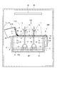
図1に示されるように、実施の形態の水耕栽培装置は、遮光性の仕切部50を備えている。仕切部50は、後に詳細に述べられるように、植物の地下部に光が到達しないようにするためのものである。仕切部50は、固定部材123と扉部材4とを備えている。固定部材123は、後述される栽培槽に対して、後述される支持部70(図2参照)を媒介として間接的に固定される。扉部材4は、後述されるように、固定部材123に対して移動可能に固定部材123に取り付けられる。
固定部材123は、板状部材1と、板状部材1に隣り合う板状部材2と、板状部材2に隣り合う板状部材3とを備えている。扉部材4は、板状部材3に隣り合う板状部材である。
板状部材1は、その厚さ方向に貫通している2つの貫通孔1Xと、板状部材2に隣接する端面に形成された半円形の2つの切欠き1Aとを有している。2つの貫通孔1Xには、後述されるビスが挿入される。切欠き1Aには、円弧状の弾性部材5が取り付けられている。
板状部材2は、その厚さ方向に貫通している2つの貫通孔2Xを有している。2つの貫通孔2Xには、後述されるビスが挿入される。板状部材2は、板状部材1に隣接する端面に形成された2つの半円形の切欠き2Aと、板状部材3に隣接する端面に形成された2つの半円形の切欠き2Bとを有している。板状部材1の半円形の切欠き1Aと板状部材2の半円形の切欠き2Aとは、一体となって、1つの円形の貫通孔を形成する。切欠き2Aおよび切欠き2Bには、それぞれ、円弧状の弾性部材5が取り付けられている。
板状部材3には、その厚さ方向に貫通している2つの貫通孔3Xが形成されている。2つの貫通孔3Xには、後述されるビスが挿入される。板状部材3は、板状部材2に隣接する端面に形成された半円形の2つの切欠き3Aを有している。板状部材2の半円形の切欠き2Bと板状部材3の半円形の切欠き3Aとは、一体となって、1つの円形の貫通孔を形成する。切欠き3Aには、円弧状の弾性部材5が取り付けられている。さらに、板状部材3には、4つのネジ穴3Cが形成されている。4つのネジ穴3Cには、後述されるネジがねじ込まれる。
上記から分かるように、板状部材1とそれに隣接する板状部材2とは、互いに対向する一対の対向面に一対の切欠き1A,2Aを有している。板状部材2とそれに隣接する板状部材3とは、互いに対向する一対の対向面に一対の切欠き2B,3Aを有している。これらの一対の切欠きは、一体となって、前述の貫通孔を形成する。
扉部材4には、その厚さ方向に貫通している2つの貫通孔4Xと4つのネジ穴4Cとが形成されている。2つの貫通孔4Xには、後述される仮止め用のビスが挿入される。4つのネジ穴4Cには、後述されるネジがねじ込まれる。扉部材4は、一方向に沿って並んで設けられた複数の板状部材の最も外側、すなわち端部の板状部材を構成している。
前述の弾性部材5は、植物の茎の形状に応じて弾性変形する。複数の弾性部材5は、いずれも、柔軟性を有する部材であることが好ましく、たとえば、ウレタンスポンジ(ウレタンフォーム)、または、ゴムスポンジ等の部材であることが好ましい。弾性部材5は、光を吸収する黒色であることが好ましい。この場合、対向する2つの弾性部材5は、弾性変形しながら、互いに協働して切欠き1A,2A,2B,3A,3Bのそれぞれと地上部11としての茎との間の隙間を閉塞する。そのため、仕切部50を設置するのと同時に、開口と茎との間の隙間を塞ぐことができる。
仕切部50は、地下部12への光の到達を抑制するためのものであるため、黒色等の光を吸収する色を有していることが望ましい。板状部材1,2,3同士の間または板状部材3と扉部材4との間に小さな隙間が存在していたとしても、黒色は光を吸収するため、地下空間を暗い状態に維持することができる。
本実施の形態においては、前述のように、仕切部50の互いに対向する板状部材の切欠き同士は、一体となって植物の茎が突き抜ける円形の開口を形成する。しかしながら、植物の茎が突き抜ける開口を構成する切欠きは、一方の板状部材にのみ設けられていてもよい。また、開口の形状は、植物10の茎が損傷しないのであれば、円形でなくてもよい。さらに、たとえば、一対の半円形の切欠きによって形成された円形の開口の直径が4cm程度であれば、4本程度の茎を束ねるのに適していることもある。円形の開口と茎との間の隙間は、仕切部50全体を覆うが、複数の茎のみが突き抜けている孔を有する柔軟性の遮光シートで覆われてもよい。
図2に示されるように、水耕栽培装置100は、栽培槽80を備えている。栽培槽80は、前述の仕切部50を支持するための支持部70を備えている。支持部70は、栽培槽80の四隅のそれぞれの内側から上下方向に延びる4つの柱部72を備えている。支持部70は、4つの長方形の枠部71を備えている。長方形の枠部71は、その4つの角部がそれぞれ4つの柱部72の上端に固定されている。
図2に示されるように、水耕栽培装置100の組み立て時には、まず、板状部材1が枠部71の上に載せられる。枠部71には、厚さ方向に貫通する貫通孔71Aが形成されている。枠部71と栽培槽80との間には、栽培槽80の内部空間と栽培槽80の外部空間とを連通させるための空気の流路20となる隙間が存在している。
植物10の地下部12は、植物10の茎が円弧状の弾性部材5に接触するように、金網9上で位置付けられる。植物10の地上部11は、仕切部50よりも上方に突出している。図2および図3においては、植物10の茎と弾性部材5との間に隙間が存在するように描かれているが、植物10の茎と弾性部材5との間に隙間が存在しなくてよい。
栽培槽80は、植物10の地下部12を収容する。栽培槽80内には、金網9が設けられている。金網9の上には植物10の地下部12が置かれている。金網9は、4つの柱部72に固定されている。植物10の地下部12から延びる根13が金網9の網目を突き抜け、金網9の下方で栽培槽80の底部に貯留されている養液81に浸っている。植物10は、根13から養液81を吸収し、成長する。
図3に示されるように、板状部材2、板状部材3、および扉部材4が、支持部70の上に載せられる。その後、8つのネジ61は、図1において示された4つのネジ穴3Cおよび4つのネジ穴4Cのそれぞれにねじ込まれている。それにより、2つのヒンジ60が、板状部材3と扉部材4とに、8つのネジ61によって固定される。したがって、扉部材4は、2つのヒンジ60に共通の回転軸まわりに、回転可能となっている。つまり、扉部材4は、開かれたり、閉じられたりされ得る状態になっている。
図4および図5に示されるように、水耕栽培装置100は、遮光部材51を備えている。遮光部材51は、固定遮光部材51Bと扉用遮光部材51Aとを含む。固定遮光部材51Bには、厚さ方向に貫通する貫通孔51B1,51B2,51B3が形成されている。扉用遮光部材51Aには、厚さ方向に貫通する貫通孔51A4が形成されている。
図4および図5から分かるように、仕切部50は、栽培槽80の上方の位置で、栽培槽80の上端の開口を覆うように設けられる。この仕切部50に対して遮光部材51が固定される。遮光部材51は、固定遮光部材51Bと扉用遮光部材51Aとが一体となることによって形成される。遮光部材51は、図4から類推されるように、平面視において、栽培槽80の4つの側面を取り囲む枠状の部材を構成し、図5から類推されるように、断面視においては、栽培槽80の側面の上部を覆う垂れ幕状の部材を構成する。
図6に示されるように、8本のビス6を用いて、仕切部50および遮光部材51が、それぞれ、枠部71に固定される。具体的には、6本のビス6は、それぞれ、固定遮光部材51Bの6つの貫通孔51B1,51B2,51B3と、それらに対応する板状部材1,2,3の6つの貫通孔1X,2X,3Xとに挿入される。また、前述の6本のビス6は、それぞれ、板状部材1,2,3の6つの貫通孔1X,2X,3Xに対応する枠部71の6つの貫通孔71Aに挿入される。その後、6本のビス6は、それぞれ、6つの貫通孔71A内に形成された雌ネジ部(図示せず)にねじ止めされる。これによれば、栽培槽80に対する板状部材1,2,3同士の位置を固定することができる。そのため、仕切部50の移動に起因した植物10の茎の損傷を抑制することができる。
仮止め用の2本のビス6は、それぞれ、扉用遮光部材51Aの2つの貫通孔51A4とそれらに対応する扉部材4の2つの貫通孔4Xに挿入される。また、仮止め用の2本のビス6は、それぞれ、扉部材4の2つの貫通孔4Xとそれらに対応する枠部71の2つの貫通孔71Aとに挿入される。扉部材4の貫通孔4Xに対応する枠部71の貫通孔71Aは、雌ネジ部を有していない。そのため、前述の仮止め用の2本のビス6は、ネジ止されていないため、扉部材4の開閉動作に伴って、扉部材4とともに移動する。
図6に示されるように、遮光部材7が仕切部50上に設けられている。6つの遮光部材7は、板状部材1,2,3のうちの隣接する2つの板状部材に跨るように設けられている。他の3つの遮光部材7は、板状部材3と扉部材4とに跨るように設けられている。遮光部材7は、板状部材1,2,3同士の間の隙間および板状部材3と扉部材4との間の隙間のそれぞれを覆っている。これによれば、板状部材1,2,3同士の間の隙間および板状部材3と扉部材4との間の隙間から栽培槽80内へ光が進入することを抑制することができる。遮光部材7は、接着テープのように板状部材1,2,3に貼り付けられるものであってもよい。また、遮光部材7は、一般に農業で使用されている遮光性のマルチシートが接着剤によって貼り付けられたものであってもよい。また、遮光部材7は、プラスチックシートであってもよい。遮光部材7は、光の吸収の観点から、黒色を有していることが好ましい。
図7に示されるように、水耕栽培装置100は、植物10の育成者が出入り可能な扉が設けられた筐体90内に設けられている。筐体90内には照明部30が設けられている。葉が植物10の地上部11に形成されると、その葉は照明部30から発せられた光によって光合成を行う。前述したように、植物10の地下部12から延びる根13は金網9の網目を通過し、養液81に浸っている。そのため、植物10は、根13から養液81を吸収することができる。
図7に示されるように、遮光部材51は、平面視において栽培槽80の外側面を取り囲み、空気の流路20が栽培槽80の外側面に沿って下方に延びるように、仕切部50の外周から垂れ下がっている。遮光部材51は、固定部材123に取り付けられた固定遮光部材51Bと、扉部材4に取り付けられ、固定遮光部材51Bから分離された扉用遮光部材51Aとを含む。
図7から分かるように、仕切部50と栽培槽80との間に空気の流路20が存在する。また、図7から類推できるように、枠部71の外周は、平面視において、栽培槽80の外周よりもひとまわり大きい。そのため、空気の流路20は、栽培槽80の外側面と遮光部材51の上下方向に延びる部分との間にも空気の流路20が延びている。したがって、たとえば、矢印Xで示されているように、空気の流路20に沿って気流が生じることにより、栽培槽80内の雰囲気と外部の雰囲気とが自然に入れ替わる。また、仕切部50と栽培槽80との間の空気の流路20が遮光部材51によって覆われている。そのため、栽培槽80内の植物10の地下部12に光が照射されることが抑制されている。
上記の構成によれば、空気の流路20を経由して栽培槽80の内側空間と栽培槽80の外側空間との間で空気を自然に流動させても、遮光部材51が栽培槽80の側方から空気の流路20を経由した栽培槽80の内側への光の進入が抑制される。加えて、植物10の育成者は、栽培槽80内の空間を視認するときには、遮光部材51とともに扉部材4を容易に開くことができる。
本実施の形態においては、支持部70が、枠組構造であり、栽培槽80と枠部71との間の隙間が空気の流路20を構成している。しかしながら、水耕栽培装置100は、空気の流路20を必要としない場合または栽培槽80に換気用の開口が設けられている場合には、支持部70を有していなくてもよい。この場合、板状部材1,2,3のそれぞれが栽培槽80の上端に直接固定されてもよい。
水耕栽培装置100は、支持部70、特に枠部71と板状部材1,2,3のそれぞれとを固定する固定用のビス6を備えていている。支持部70は、栽培槽80に固定されており、板状部材1,2,3は、支持部70を媒介として、栽培槽80に対して間接的に固定されている。板状部材1,2,3は、ビス6の代わりに、釘、接着剤、セロハンテープ、または面ファスナ(マジックテープ(登録商標))等のいなかるものによって支持部70に固定されてもよい。これによれば、栽培槽80に対する板状部材1,2,3の位置を固定することができる。そのため、仕切部50の移動に起因した植物10の茎の損傷を抑制することができる。
図7に示されるように、仕切部50は、植物10の地上部11が成長する地上空間11Aと植物10の地下部12が成長する地下空間12Aとを仕切っている。仕切部50は、上述された固定部材123および扉部材4を含む。
図8に示されるように、矢印Yで示される方向に、植物10の栽培中に扉部材4をヒンジ60の回転軸まわりに回転させる。それにより、扉部材4を開くことができる。このとき、扉用遮光部材51Aは、扉部材4に仮止め用のビス6で取り付けられているため、扉部材4とともに移動する。そのため、植物10の育成者は、育成中に植物10の地下部12の状態を視認することができる。図8においては、扉用遮光部材51Aは、ある程度の硬さを有しているため、扉部材4の移動に伴って、その形状が変化しないように描かれている。しかしながら、扉用遮光部材51Aは、柔軟性を有するシート、布、またはビニール等で形成されている場合には、扉部材4の開閉動作によって、その形状が変化してもよい。
図8から分かるように、固定部材123は、栽培槽80に対する位置が固定され、地下空間12Aに光が進入することを抑制する閉状態を維持する。一方、扉部材4は、固定部材123に対して移動可能な状態で固定部材123に取り付けられ、地下空間12Aに光が進入することを抑制する閉状態と地下空間12Aが視認され得る開状態とに変化する。つまり、扉部材4は、植物10の地下部12に光が照射される閉状態と、植物10の地下部12を視認し得る開状態とに変化する。そのため、植物10の育成者は、扉部材4を開くことにより、栽培槽80の内側の空間の植物10の地下部12を栽培槽80の上方から視認することができる。つまり、扉部材4を開くという簡単な作業によって栽培槽80内の地下部12を視認することができる。また、扉部材4を開いた状態にすれば、地下部12の写真撮影を容易に行うことができる。
図8に示されるように、遮光部材7は、扉部材4が開かれるとヒンジ60の回転軸に沿って折り曲げられる程度に柔軟性を有している。そのため、遮光部材7は、扉部材4の開閉動作を阻害しない。また、遮光部材7は、扉部材4の開閉動作によって破壊されない。
図8に示されるように、本実施の形態においては、扉部材4は、固定部材123にヒンジ60を媒介として取り付けられ、固定部材123に対して回転可能な開き戸である。しかしながら、扉部材4は、固定部材123の溝に対してスライド可能に取り付けられた引き戸であってもよい。
図8に示されるように、扉部材4は、仕切部50の端部を構成している。そのため、扉部材4に取っ手を設けなくても、植物10の育成者は扉部材4を開けることが容易である。
次に、図9を用いて、実施の形態の水耕栽培装置100の変形例の遮光部材51を説明する。図9に示されるように、実施の形態の水耕栽培装置100の変形例の遮光部材51は、枠部71に固定されている。つまり、遮光部材51は、仕切部50と枠部71とによって挟まれている。この場合、遮光部材51は、扉部材4とともに動くことはなく、常に、空気の流路20を覆っている。言い換えると、扉部材4のみが、開かれたり、閉じられたりする。そのため、扉部材4の開閉を容易に行うことができる。また、図4に示された固定遮光部材51Bと扉用遮光部材51Aとは、分離されておらず、一体成形されていてもよい。さらに、遮光部材51は、図4に示された全体形状と同一の形状を有しているが、一連の薄板の組み立てまたはビニールシートの縫い合わせ等によって形成されていてもよい。つまり、変形例の水耕栽培装置100においても、遮光部材51は、平面視において栽培槽80の側面を取り囲み、空気の流路20が栽培槽80の側面に沿って下方に延びるように、仕切部50の外周から垂れ下がっていればよい。これによっても、空気の流路20を経由した光の地下空間12Aへの進入を抑制しながら、地下空間12Aの換気を行うことができる。さらに、この変形例によれば、1つの部品として遮光部材51を形成することができるため、遮光部材51をより簡単に形成することができる。
以下、実施の形態の水耕栽培装置100の特徴的構成およびそれにより得られる効果を説明する。
(1) 水耕栽培装置100は、遮光性の栽培槽80および遮光性の仕切部50を備えている。栽培槽80は、植物10の地下部12を収容するように構成されている。遮光性の仕切部50は、栽培槽80の上端の開口を覆うように設けられ、植物10の地下部12が成長する地下空間12Aと植物10の地上部11が成長する地上空間11Aとを仕切る。仕切部50は、固定部材123および扉部材4を含む。固定部材123は、栽培槽80に対する位置が固定され、植物10の茎を取り囲む貫通孔を有し、植物10の地下部12に光が照射されることを抑制する閉状態を維持する。扉部材4は、固定部材123に対して移動可能な状態で固定部材123に取り付けられ、植物10の地下部12に光が照射されることを抑制する閉状態と植物10の地下部12を視認し得る開状態とに変化する。
上記の構成によれば、植物10の育成者は、扉部材4を開くことにより、栽培槽80の内側の空間の植物10の地下部12を栽培槽80の上方から視認することができる。
(2) 扉部材4は、固定部材123にヒンジ60を媒介として取り付けられ、固定部材123に対してヒンジ60の回転軸まわりに回転可能な開き戸であってもよい。この場合、水耕栽培装置100は、遮光部材7をさらに備えていることが好ましい。遮光部材7は、扉部材4と固定部材123との間の隙間を覆うように設けられ、扉部材4が開かれるとヒンジ60の回転軸に沿って折り曲げられる。
上記の構成によれば、遮光部材7によって、扉部材4の開閉動作を阻害することなく、扉部材4と固定部材123との間の隙間から栽培槽80の内部へ光が進入することを抑制することができる。
(3) 扉部材4は、仕切部50の端部を構成することが好ましい。これによれば、扉部材4に取っ手を設けなくても、扉部材4を容易に開くことができる。
(4) 水耕栽培装置100は、支持部70および遮光部材51をさらに備えていてもよい。この場合、支持部70は、栽培槽80に設置され、栽培槽80と仕切部50との間に空気の流路20が形成されるように、栽培槽80の上端部よりも上方で仕切部50を支持する。遮光部材51は、平面視において栽培槽80の側面を取り囲み、空気の流路20が栽培槽80の側面に沿って下方に延びるように、仕切部50の外周から垂れ下がる。遮光部材51は、固定部材123に取り付けられた固定遮光部材51Bと、扉部材4に取り付けられ、固定遮光部材51Bから分離された扉用遮光部材51Aとを含む。
上記の構成によれば、空気の流路20を経由して栽培槽80の内側空間と栽培槽80の外側空間との間で空気を自然に流動させても、遮光部材51が栽培槽80の側方から空気の流路20を経由した栽培槽80の内側への光の進入を抑制する。加えて、栽培槽80内を視認するときには、遮光部材51とともに扉部材4を容易に開くことができる。
(5) 固定部材123は、互いに隣接する板状部材1,2,3を含んでいてもよい。この場合、貫通孔は、隣接する板状部材1,2,3の一方の端面に形成された切欠き、または、隣接する板状部材1,2,3の一対の対向面に設けられた一対の切欠き1A,2A,2B,3Aによって形成されていてもよい。これによれば、仕切部50の設置を容易に行うことができる。
(6) 切欠き1A,2A,2B,3Aの内面には、植物10の茎と切欠きとの間の隙間を塞ぎ、茎の形状に応じて弾性変形する弾性部材5が取り付けられていることが好ましい。これによれば、植物10の茎と切欠きとの間の隙間を経由して植物10の地下部12に光が照射されてしまうことが抑制される。
(7) 隣接する板状部材1,2,3同士の間の隙間を覆う遮光部材7をさらに備えていることが好ましい。これによれば、植物10の茎と切欠きとの間の隙間を経由して植物10の地下部12に光が照射されてしまうことが抑制される。
本出願は、2016年2月8日に出願された日本出願の特願2016-021862号に基づく優先権を主張し、当該日本出願に記載された全ての記載内容を参照によって援用するものである。
本出願は、2016年2月8日に出願された日本出願の特願2016-021862号に基づく優先権を主張し、当該日本出願に記載された全ての記載内容を参照によって援用するものである。
1,2,3 板状部材
1A,2A,2B,3A 切欠き(貫通孔)
4 扉部材
5 弾性部材
7 遮光部材
10 植物
11 地上部
11A 地上空間
12 地下部
12A 地下空間
20 空気の流路
50 仕切部
51 遮光部材
51B 固定遮光部材
51A 扉用遮光部材
60 ヒンジ
70 支持部
80 栽培槽
100 水耕栽培装置
123 固定部材
1A,2A,2B,3A 切欠き(貫通孔)
4 扉部材
5 弾性部材
7 遮光部材
10 植物
11 地上部
11A 地上空間
12 地下部
12A 地下空間
20 空気の流路
50 仕切部
51 遮光部材
51B 固定遮光部材
51A 扉用遮光部材
60 ヒンジ
70 支持部
80 栽培槽
100 水耕栽培装置
123 固定部材
Claims (7)
- 植物の地下部を収容するように構成された遮光性の栽培槽と、
前記栽培槽の上端の開口を覆うように設けられ、前記植物の地下部が成長する地下空間と前記植物の地上部が成長する地上空間とを仕切る遮光性の仕切部と、を備え、
前記仕切部は、
前記栽培槽に対する位置が固定され、前記植物の茎を取り囲む貫通孔を有し、前記植物の地下部に光が照射されることを抑制する閉状態を維持する固定部材と、
前記固定部材に対して移動可能な状態で前記固定部材に取り付けられ、前記植物の地下部に光が照射されることを抑制する閉状態と前記植物の地下部を視認し得る開状態とに変化する扉部材と、を含む、水耕栽培装置。 - 前記扉部材は、前記固定部材にヒンジを媒介として取り付けられ、前記固定部材に対して前記ヒンジの回転軸まわりに回転可能な開き戸であり、
前記扉部材と前記固定部材との間の隙間を覆うように設けられ、前記扉部材が開かれると前記ヒンジの回転軸に沿って折り曲げられる遮光部材をさらに備えた、請求項1に記載の水耕栽培装置。 - 前記扉部材は、前記仕切部の端部を構成する、請求項1または2に記載の水耕栽培装置。
- 前記栽培槽に設置され、前記栽培槽と前記仕切部との間に空気の流路が形成されるように、前記栽培槽の上端部よりも上方で前記仕切部を支持する支持部と、
平面視において前記栽培槽の側面を取り囲み、前記空気の流路が前記栽培槽の側面に沿って下方に延びるように、前記仕切部の外周から垂れ下がる遮光部材と、をさらに備え、
前記遮光部材は、前記固定部材に取り付けられた固定遮光部材と、前記扉部材に取り付けられ、前記固定遮光部材から分離された扉用遮光部材とを含む、請求項1~3のいずれかに記載の水耕栽培装置。 - 前記固定部材は、互いに隣接する板状部材を含み、
前記貫通孔は、前記隣接する板状部材の一方の端面に形成された切欠き、または、前記隣接する板状部材の一対の対向面に設けられた一対の切欠きによって形成された、請求項1~4のいずれかに記載の水耕栽培装置。 - 前記切欠きの内面には、前記植物の茎と前記切欠きとの間の隙間を塞ぎ、前記茎の形状に応じて弾性変形する弾性部材が取り付けられた、請求項5に記載の水耕栽培装置。
- 前記隣接する板状部材同士の間の隙間を覆う遮光部材をさらに備えた、請求項5または6に記載の水耕栽培装置。
Priority Applications (4)
| Application Number | Priority Date | Filing Date | Title |
|---|---|---|---|
| JP2017566242A JP6650631B2 (ja) | 2016-02-08 | 2016-12-09 | 水耕栽培装置 |
| EP16889758.5A EP3414996B1 (en) | 2016-02-08 | 2016-12-09 | Hydroponic device |
| CN201680072994.5A CN108366538B (zh) | 2016-02-08 | 2016-12-09 | 水培装置 |
| US16/061,447 US20200260666A1 (en) | 2016-02-08 | 2016-12-09 | Hydroponic cultivation apparatus |
Applications Claiming Priority (2)
| Application Number | Priority Date | Filing Date | Title |
|---|---|---|---|
| JP2016021862 | 2016-02-08 | ||
| JP2016-021862 | 2016-02-08 |
Publications (1)
| Publication Number | Publication Date |
|---|---|
| WO2017138054A1 true WO2017138054A1 (ja) | 2017-08-17 |
Family
ID=59562940
Family Applications (1)
| Application Number | Title | Priority Date | Filing Date |
|---|---|---|---|
| PCT/JP2016/005091 Ceased WO2017138054A1 (ja) | 2016-02-08 | 2016-12-09 | 水耕栽培装置 |
Country Status (5)
| Country | Link |
|---|---|
| US (1) | US20200260666A1 (ja) |
| EP (1) | EP3414996B1 (ja) |
| JP (1) | JP6650631B2 (ja) |
| CN (1) | CN108366538B (ja) |
| WO (1) | WO2017138054A1 (ja) |
Cited By (4)
| Publication number | Priority date | Publication date | Assignee | Title |
|---|---|---|---|---|
| CN111491505A (zh) * | 2017-12-13 | 2020-08-04 | 松下知识产权经营株式会社 | 水耕栽培装置 |
| JP2020141621A (ja) * | 2019-03-07 | 2020-09-10 | 学校法人近畿大学 | 節足動物の痕跡調査方法および液体回収器 |
| WO2020241418A1 (ja) * | 2019-05-29 | 2020-12-03 | パナソニックIpマネジメント株式会社 | 水耕栽培装置 |
| JP2021159043A (ja) * | 2020-04-03 | 2021-10-11 | パナソニックIpマネジメント株式会社 | 水耕栽培装置 |
Families Citing this family (4)
| Publication number | Priority date | Publication date | Assignee | Title |
|---|---|---|---|---|
| CN107148902A (zh) * | 2017-05-22 | 2017-09-12 | 福建省中科生物股份有限公司 | 一种双色栽培装置 |
| KR102383609B1 (ko) * | 2019-11-27 | 2022-04-06 | 주식회사 미드바르 | 공기에서 추출된 물을 이용한 식물 재배 시스템 |
| US12588610B2 (en) * | 2020-12-10 | 2026-03-31 | Keerti Ayakannu | Growing container for free-rooted plants and system and method using same |
| EP4333607A4 (en) * | 2021-05-06 | 2024-10-23 | Phenoroot Ltd. | ROOT ZONE TEMPERATURE REGULATION SYSTEM |
Citations (7)
| Publication number | Priority date | Publication date | Assignee | Title |
|---|---|---|---|---|
| JPS5824165U (ja) * | 1981-08-10 | 1983-02-15 | 村井 邦彦 | ビニ−ルシ−ツ形水耕栽培装置 |
| JPS645434A (en) * | 1987-06-27 | 1989-01-10 | Aoshima Reitou Kogyo Kk | Culture of plant and apparatus therefor |
| JPH04103454U (ja) * | 1991-02-15 | 1992-09-07 | 庄三郎 木田 | 水耕栽培装置 |
| JPH04271731A (ja) * | 1991-02-28 | 1992-09-28 | Tabai Espec Corp | 人工光型植物栽培装置 |
| JPH07227162A (ja) * | 1994-02-18 | 1995-08-29 | Sekisui Plastics Co Ltd | 養液栽培装置 |
| WO2014188932A1 (ja) * | 2013-05-23 | 2014-11-27 | 有限会社グリーンスペース造園 | 水耕栽培キット |
| JP2016010388A (ja) * | 2014-06-30 | 2016-01-21 | 菱江化学株式会社 | 栽培床、栽培床を使用する植物栽培装置、及び植物栽培装置を使用する方法 |
Family Cites Families (25)
| Publication number | Priority date | Publication date | Assignee | Title |
|---|---|---|---|---|
| US3660933A (en) * | 1970-03-02 | 1972-05-09 | Weingarten & Wong Enterprises | Hydroponics system and method |
| US4057930A (en) * | 1974-08-12 | 1977-11-15 | Barham Rayford A | Hydroponic method and apparatus |
| JPS51129735A (en) * | 1975-04-30 | 1976-11-11 | Mitsubishi Petrochemical Co | Hydroponics by using foamed rough plate |
| JPS5512349U (ja) * | 1978-07-11 | 1980-01-26 | ||
| JPS58146453U (ja) * | 1982-03-29 | 1983-10-01 | 田口 悌二 | 観賞用植物の水栽培器 |
| US4531324A (en) * | 1983-10-07 | 1985-07-30 | Agracetus | Plant tissue culture device |
| US4908985A (en) * | 1988-06-06 | 1990-03-20 | Pathway Systems, Inc. | System and apparatus for hydroponic gardening |
| JP2557844Y2 (ja) * | 1991-11-26 | 1997-12-17 | 恵庸 豊村 | 水耕栽培プランター |
| JPH0588251U (ja) * | 1992-05-01 | 1993-12-03 | 勝紀 上野 | 構造物に取り付ける養液栽培装置および栽培槽 |
| JP3505046B2 (ja) * | 1996-09-30 | 2004-03-08 | 日本たばこ産業株式会社 | バレイショ塊茎生産方法 |
| JP2917140B1 (ja) * | 1998-02-23 | 1999-07-12 | 株式会社広瀬 | 床土又は瀘材の製造方法 |
| JP2000060329A (ja) * | 1998-08-26 | 2000-02-29 | Toto Kogyo Kk | 作物の養液栽培方法及び栽培装置 |
| GB2368767B (en) * | 2000-11-13 | 2004-01-07 | Wen-Chi Lai | Bean sprout culture box with a sprinkling device |
| US7426802B2 (en) * | 2003-07-18 | 2008-09-23 | Umbaugh Jr Raymond E | Seed germination and paint supporting utility |
| US8291639B2 (en) * | 2009-09-09 | 2012-10-23 | S and E Properties, Inc. | Growing system for hydroponics and/or aeroponics |
| US20120186153A1 (en) * | 2011-01-26 | 2012-07-26 | American Agritech, L.L.C. | Device, system and methods for hydroponic gardening |
| CN202842037U (zh) * | 2012-08-21 | 2013-04-03 | 昆明理工大学 | 一种基于遮光布的喷雾栽培箱 |
| JP5639701B1 (ja) * | 2013-09-12 | 2014-12-10 | パナソニック株式会社 | 水耕栽培装置及び水耕栽培方法 |
| JP6172647B2 (ja) * | 2014-02-28 | 2017-08-02 | パナソニックIpマネジメント株式会社 | 水耕栽培装置とそれを用いた水耕栽培方法 |
| JP6269274B2 (ja) * | 2014-04-11 | 2018-01-31 | パナソニックIpマネジメント株式会社 | 水耕栽培装置及び水耕栽培方法 |
| KR101590808B1 (ko) * | 2014-05-12 | 2016-02-03 | 주식회사 와이엔씨 | 가정용 수경재배 장치 |
| CN204929894U (zh) * | 2015-08-27 | 2016-01-06 | 青岛海尔智能技术研发有限公司 | 生态种植箱 |
| US10072880B2 (en) * | 2015-09-14 | 2018-09-11 | Herbert Newsam | Self-contained plant cloning system and method |
| CN105284586B (zh) * | 2015-11-16 | 2019-01-25 | 乐农同创(北京)科技有限公司 | 栽培装置及半自动水培芽苗菜栽培方法 |
| US10653075B1 (en) * | 2018-12-07 | 2020-05-19 | Timothy E. Joseph | Modular grow chamber constructions and related growing systems and methods |
-
2016
- 2016-12-09 CN CN201680072994.5A patent/CN108366538B/zh active Active
- 2016-12-09 US US16/061,447 patent/US20200260666A1/en not_active Abandoned
- 2016-12-09 WO PCT/JP2016/005091 patent/WO2017138054A1/ja not_active Ceased
- 2016-12-09 JP JP2017566242A patent/JP6650631B2/ja active Active
- 2016-12-09 EP EP16889758.5A patent/EP3414996B1/en active Active
Patent Citations (7)
| Publication number | Priority date | Publication date | Assignee | Title |
|---|---|---|---|---|
| JPS5824165U (ja) * | 1981-08-10 | 1983-02-15 | 村井 邦彦 | ビニ−ルシ−ツ形水耕栽培装置 |
| JPS645434A (en) * | 1987-06-27 | 1989-01-10 | Aoshima Reitou Kogyo Kk | Culture of plant and apparatus therefor |
| JPH04103454U (ja) * | 1991-02-15 | 1992-09-07 | 庄三郎 木田 | 水耕栽培装置 |
| JPH04271731A (ja) * | 1991-02-28 | 1992-09-28 | Tabai Espec Corp | 人工光型植物栽培装置 |
| JPH07227162A (ja) * | 1994-02-18 | 1995-08-29 | Sekisui Plastics Co Ltd | 養液栽培装置 |
| WO2014188932A1 (ja) * | 2013-05-23 | 2014-11-27 | 有限会社グリーンスペース造園 | 水耕栽培キット |
| JP2016010388A (ja) * | 2014-06-30 | 2016-01-21 | 菱江化学株式会社 | 栽培床、栽培床を使用する植物栽培装置、及び植物栽培装置を使用する方法 |
Non-Patent Citations (1)
| Title |
|---|
| See also references of EP3414996A4 * |
Cited By (6)
| Publication number | Priority date | Publication date | Assignee | Title |
|---|---|---|---|---|
| CN111491505A (zh) * | 2017-12-13 | 2020-08-04 | 松下知识产权经营株式会社 | 水耕栽培装置 |
| EP3725151A4 (en) * | 2017-12-13 | 2021-01-27 | Panasonic Intellectual Property Management Co., Ltd. | HYDROPONIC DEVICE |
| JP2020141621A (ja) * | 2019-03-07 | 2020-09-10 | 学校法人近畿大学 | 節足動物の痕跡調査方法および液体回収器 |
| JP7260901B2 (ja) | 2019-03-07 | 2023-04-19 | 学校法人近畿大学 | 節足動物の痕跡調査方法および液体回収器 |
| WO2020241418A1 (ja) * | 2019-05-29 | 2020-12-03 | パナソニックIpマネジメント株式会社 | 水耕栽培装置 |
| JP2021159043A (ja) * | 2020-04-03 | 2021-10-11 | パナソニックIpマネジメント株式会社 | 水耕栽培装置 |
Also Published As
| Publication number | Publication date |
|---|---|
| CN108366538B (zh) | 2020-06-16 |
| JP6650631B2 (ja) | 2020-02-19 |
| CN108366538A (zh) | 2018-08-03 |
| US20200260666A1 (en) | 2020-08-20 |
| EP3414996A4 (en) | 2019-01-23 |
| JPWO2017138054A1 (ja) | 2018-10-11 |
| EP3414996B1 (en) | 2021-02-03 |
| EP3414996A1 (en) | 2018-12-19 |
Similar Documents
| Publication | Publication Date | Title |
|---|---|---|
| WO2017138054A1 (ja) | 水耕栽培装置 | |
| US10219446B2 (en) | Plant growing apparatus | |
| US5524383A (en) | Disassembleable portable cold frame apparatus | |
| WO2020241418A1 (ja) | 水耕栽培装置 | |
| JP5986451B2 (ja) | 水耕栽培用プレート及びこれを備えた水耕栽培ユニット | |
| KR102198100B1 (ko) | 착탈식 안전 방충망 | |
| KR101823575B1 (ko) | 작물재배용 미니비닐하우스 | |
| KR102348916B1 (ko) | 관찰용 벌통 | |
| KR20010047446A (ko) | 나비 사육 테라륨용 캡슐 화분 | |
| JP2015229156A (ja) | フィルタ | |
| KR101658104B1 (ko) | 온실 지붕 방충 및 차광 스크린 구조 | |
| JP4771752B2 (ja) | ハウスの換気扇用の防虫ネットシステム | |
| JP3189615U (ja) | プランタ | |
| ES1298801U (es) | Mosquitera enrollable con un cabezal desmontable | |
| US20250380646A1 (en) | Plant pot | |
| KR20260035030A (ko) | 동물실험용 케이지 | |
| KR20160095424A (ko) | 다육식물 재배장치 | |
| KR20200004067A (ko) | 다목적 곤충 케이스 | |
| JP2007014221A (ja) | 温室の換気装置 | |
| US11432536B2 (en) | Aquarium conversion systems | |
| TW201313896A (zh) | 牛樟芝之培養裝置 | |
| JP2011147393A (ja) | マルハナバチ用巣箱 | |
| AU2005201553A1 (en) | Animal caging system | |
| JPH1156109A (ja) | 植物栽培用容器 | |
| JP2020014431A (ja) | 園芸用ハウス |
Legal Events
| Date | Code | Title | Description |
|---|---|---|---|
| 121 | Ep: the epo has been informed by wipo that ep was designated in this application |
Ref document number: 16889758 Country of ref document: EP Kind code of ref document: A1 |
|
| ENP | Entry into the national phase |
Ref document number: 2017566242 Country of ref document: JP Kind code of ref document: A |
|
| NENP | Non-entry into the national phase |
Ref country code: DE |