WO2017138134A1 - Dispositif de commande d'application de pression pour literie - Google Patents
Dispositif de commande d'application de pression pour literie Download PDFInfo
- Publication number
- WO2017138134A1 WO2017138134A1 PCT/JP2016/054055 JP2016054055W WO2017138134A1 WO 2017138134 A1 WO2017138134 A1 WO 2017138134A1 JP 2016054055 W JP2016054055 W JP 2016054055W WO 2017138134 A1 WO2017138134 A1 WO 2017138134A1
- Authority
- WO
- WIPO (PCT)
- Prior art keywords
- pressure
- bedding
- unit
- control circuit
- air
- Prior art date
- Legal status (The legal status is an assumption and is not a legal conclusion. Google has not performed a legal analysis and makes no representation as to the accuracy of the status listed.)
- Ceased
Links
Images






Classifications
-
- A—HUMAN NECESSITIES
- A47—FURNITURE; DOMESTIC ARTICLES OR APPLIANCES; COFFEE MILLS; SPICE MILLS; SUCTION CLEANERS IN GENERAL
- A47C—CHAIRS; SOFAS; BEDS
- A47C27/00—Spring, stuffed or fluid mattresses or cushions specially adapted for chairs, beds or sofas
- A47C27/08—Fluid mattresses
- A47C27/10—Fluid mattresses with two or more independently-fillable chambers
Definitions
- the present invention relates to a pressure control device for bedding that supports a user's body.
- Patent Document 1 a pressurizable bedding that performs massage or the like by applying pressure to each part of a user's body is known (for example, Patent Document 1).
- the bedding disclosed in Patent Document 1 includes a plurality of actuators arranged in a matrix and a control device that centrally controls the plurality of actuators.
- a predetermined pressure is applied to each part of the body by controlling each of the plurality of actuators.
- an object of the present invention is to provide a pressure control device for bedding that applies pressure to each part of a user's body, and is lightweight and low-cost.
- a pressure control device for bedding is a pressure control device for bedding that supports the body of a user, and is a plurality of daisy chain connected and parallel computing devices. And a plurality of pressurizing units that are respectively controlled by the plurality of control circuits and apply pressure to the body.
- each of the plurality of pressurizing units is controlled by one control circuit corresponding to the pressurizing unit among the plurality of control circuits, the control device for centrally controlling the plurality of pressurizing units. Is unnecessary. Further, the communication wires connected to each control circuit need only be wires for daisy chain connection. Therefore, the cost required for the electric wires and the weight of the pressure control device for bedding can be suppressed.
- Each control circuit only needs to control one pressurizing unit. Therefore, since the processing load of each control circuit is small, the processing capability required for each control circuit can be reduced. For this reason, the cost which a control circuit requires can be suppressed.
- the plurality of control circuits are daisy chain connected by a single-core electric wire, and each of the plurality of control circuits is connected to a common ground. May be.
- the weight and cost of the wire used for daisy chain connection can be further suppressed.
- each of the plurality of pressure units includes an air ball disposed at an end on the body side, and the air pressure inside the air ball is controlled. You may adjust.
- the pressure control device for bedding supports the body in the air ball, when the body contacts the pressure control device for bedding, the impact applied to both the body and the pressure unit is reduced. Can do.
- the apparatus may further include a single hose that supplies air to the plurality of pressure units.
- each of the plurality of pressure units may include a linear actuator that adjusts the position of the end portion on the body side.
- the pressure control device for bedding may further include a pressure sensor that detects a pressure applied to the pressure unit.
- the pressure applied to each pressurizing part can be adjusted based on the detection value of the pressure sensor. Moreover, a user's weight can be measured using the detection value of a some pressure sensor.
- each of the plurality of control circuits may detect the respiration rate information of the user based on a detection result of the pressure sensor.
- based on the user's breathing information for example, it can be detected that the user is in an apnea state.
- the pressure applied to the body may be varied by at least one of the plurality of pressurizing units.
- the user who is in an apnea state can be awakened and respiration can be resumed.
- each of the plurality of control circuits may detect the heart rate information of the user based on a detection result of the pressure sensor.
- the user's arrhythmia can be recorded and an alarm can be issued when cardiac arrest is detected.
- the plurality of control circuits may perform pipeline processing.
- the weight of the user can be calculated by using a plurality of control circuits using, for example, a pressure sensor.
- a pressure control device for bedding that applies pressure to each part of the user's body, and is lightweight and low-cost.
- FIG. 1 is a perspective view showing an outline of a configuration of a pressure control device for bedding according to an embodiment.
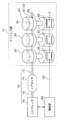
- FIG. 2 is a schematic diagram illustrating a connection mode of each component of the pressure control device for bedding according to the embodiment.
- FIG. 3 is a block diagram illustrating a functional configuration of the operation unit according to the embodiment.
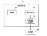
- FIG. 4 is a block diagram illustrating a functional configuration of the arrangement specifying unit according to the embodiment.
- FIG. 5 is a side view showing the appearance of the pressure unit according to the embodiment.
- FIG. 6 is an exploded perspective view showing the configuration of the pressurizing unit according to the embodiment.
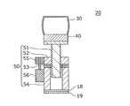
- FIG. 7 is a cross-sectional view illustrating a configuration of the pressurizing unit according to the embodiment.
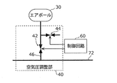
- FIG. 8 is a piping diagram illustrating a schematic configuration of the air pressure adjusting unit according to the embodiment.
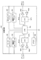
- FIG. 9 is a schematic circuit diagram illustrating a configuration of a control circuit according to the embodiment.
- FIG. 10 is a schematic diagram illustrating a connection mode of the control circuit according to the embodiment.
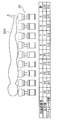
- FIG. 11 is a schematic diagram illustrating a state of the pressurizing unit before the pressure equalizing operation is performed in the pressure control device for bedding according to the embodiment.
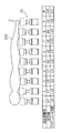
- FIG. 12 is a schematic diagram illustrating a state of the pressurizing unit after performing the pressure equalizing operation in the pressure control device for bedding according to the embodiment.
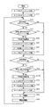
- FIG. 13 is a flowchart illustrating a control procedure in the pressure equalizing operation of the control circuit according to the embodiment.
- FIG. 14 is a flowchart illustrating a control procedure in the average pressure value calculating operation of the control circuit according to the embodiment.
- FIG. 1 is a perspective view showing an outline of the configuration of a pressure control apparatus 10 for bedding according to the present embodiment.
- FIG. 2 is a schematic diagram showing a connection mode of each component of the pressure control apparatus 10 for bedding according to the present embodiment.
- the pressure control device 10 for bedding is a device that supports the user's body. As shown in FIG. 1, the bedding pressure control apparatus 10 according to the present embodiment includes a mattress unit 12 and an air supply unit 70. In the present embodiment, the bedding pressure control apparatus 10 further includes an operation unit 80, a headboard 16, and an arrangement specifying unit 90.
- the mattress portion 12 is a mattress-like portion that supports the user's body.
- the mattress unit 12 includes a plurality of control circuits 60 and a plurality of pressure units 20 as shown in FIG. Further, in the present embodiment, as shown in FIG. 1, the mattress unit 12 further includes a cover 14 that covers the plurality of pressure units 20 and the plurality of control circuits 60.
- the plurality of control circuits 60 are circuits that are connected in a daisy chain and perform parallel computing, and control the driving of the pressure unit 20.
- the detailed configuration of each control circuit 60 will be described later.
- the plurality of pressurizing units 20 are devices that are respectively controlled by the plurality of control circuits 60 and apply pressure to the user's body.
- the pressurizing unit 20 is arranged in a 40 ⁇ 20 matrix, for example. As shown in FIG. 2, the pressurizing unit 20 includes an air ball 30, an air pressure adjusting unit 40, a linear actuator 50, and a control circuit 60. The detailed configuration of each pressure unit 20 will be described later.
- the cover 14 shown in FIG. 1 is a bag-like member that covers the plurality of pressure units 20.
- the material of the cover 14 is not particularly limited.
- a material of the cover 14 for example, a polyester-based synthetic fiber can be used.
- the air supply unit 70 shown in FIGS. 1 and 2 is a device that supplies air (air) to the air ball 30 and the air pressure adjustment unit 40 of each of the plurality of pressurizing units 20.
- the configuration of the air supply unit 70 is not particularly limited as long as air can be supplied. Further, the air supply unit 70 may supply a gas such as nitrogen other than air.
- the air supply unit 70 includes a compressor 76, an air tank 74, and hoses 72 and 75.
- the compressor 76 shown in FIGS. 1 and 2 is a device that supplies pressurized air to the plurality of pressurizing units 20.
- the air discharged from the compressor 76 is supplied to the air tank 74 via the hose 75.
- the configuration of the compressor 76 is not particularly limited. Any known compressor can be used as the compressor 76.
- the air tank 74 shown in FIGS. 1 and 2 is a tank that temporarily stores the air discharged from the compressor 76.
- the air tank 74 has a function as a buffer for suppressing the pressure fluctuation of the air discharged from the compressor 76 from being transmitted to the pressurizing unit 20, and also has a function of storing the pressurized air.
- air can be stored in the air tank 74 by driving the compressor 76 before using the bedding pressure control device 10.
- the pressure applied to the body by the pressurizing unit 20 can be adjusted by stopping the compressor 76 and supplying the air stored in the air tank 74 to the pressurizing unit 20. .
- the compressor 76 can be stopped when using the pressure control apparatus 10 for bedding, noise caused by the compressor 76 can be reduced.
- the material of the hose 72 is not particularly limited. As the hose 72, any known hose suitable for air pressure can be used.
- the hose 75 shown in FIGS. 1 and 2 is a hose for supplying air from the compressor 76 to the air tank 74.
- the configuration of the hose 75 is the same as that of the hose 72.
- the operation unit 80 shown in FIGS. 1 and 2 is a device for operating the pressure control device 10 for bedding. As shown in FIG. 2, the operation unit 80 is connected to the control circuit 60 by an electric wire 82. In the present embodiment, as shown in FIG. 1, the operation unit 80 includes a display unit 84 that is a user interface and an operation button 86 that is an input unit.
- the functional configuration of the operation unit 80 will be described with reference to FIG. 3 in addition to FIGS. 1 and 2.
- FIG. 3 is a block diagram showing a functional configuration of the operation unit 80 according to the present embodiment. 3 also shows a control circuit 60 and a compressor 76 operated by the operation unit 80, and an arrangement specifying unit 90 that outputs a signal to the operation unit 80.
- the operation unit 80 functionally includes an input unit 85, a display unit 84, an operation unit control circuit 88, and a communication unit 89.
- the input unit 85 is a functional unit for a user to input an operation signal.
- the input unit 85 includes a plurality of operation buttons 86 shown in FIG.
- the display unit 84 is a user interface that displays an operation status and the like.
- the display unit 84 is composed of, for example, a liquid crystal panel.
- the operation unit control circuit 88 is a processing unit that generates an image signal based on an operation signal input by the user using the input unit 85 and transmits the image signal to the display unit 84.
- the operation unit control circuit 88 generates a control signal to be transmitted to each of the compressor 76 and the control circuit 60 based on the operation signal, and transmits the control signal to the communication unit 89.
- the communication unit 89 is a processing unit that transmits the control signal transmitted from the operation unit control circuit 88 to the compressor 76, the control circuit 60, and the arrangement specifying unit 90.
- Each processing unit of the operation unit 80 is realized by, for example, a microcomputer including a program, a memory, and a processor.
- the operation unit 80 Since the operation unit 80 is configured as described above, the user can operate the bedding pressure control apparatus 10 by pressing the operation button 86.
- the headboard 16 shown in FIG. 1 is a plate-like member disposed at the end of the mattress portion 12 in the longitudinal direction.
- the material of the head board 16 is not particularly limited.
- an arrangement specifying unit 90 is arranged on the headboard 16.
- the arrangement specifying unit 90 is a processing unit that specifies the arrangement of the user's body.
- the arrangement specifying unit 90 includes an imaging unit 92, and pressurization corresponding to each part of the body among the plurality of pressurization units 20 based on the user's body imaged by the imaging unit 92 and the image of the mattress unit 12.
- the part 20 is specified.
- the arrangement specifying unit 90 will be described with reference to the drawings.
- FIG. 4 is a block diagram showing a functional configuration of the arrangement specifying unit 90 according to the present embodiment.
- the operation unit 80 is also shown together with the arrangement specifying unit 90.
- the arrangement specifying unit 90 functionally includes an imaging unit 92, an image processing unit 94, and an arrangement information communication unit 96.
- the imaging unit 92 is a camera that captures images of the user's body and the mattress unit 12.
- the image processing unit 94 is a processing unit that identifies the pressing unit 20 corresponding to each part of the body among the plurality of pressing units 20 based on the image captured by the imaging unit 92.
- the image processing unit 94 includes arrangement information of each pressing unit 20 in the mattress unit 12 in advance.
- the image processing unit 94 detects that the user's body exists on the mattress unit 12 by performing image processing, the image processing unit 94 indicates the correspondence between the position of each part of the body and the position of each pressurizing unit 20. Arrangement information is generated, and the arrangement information is transmitted to the arrangement information communication unit 96.
- the arrangement information communication unit 96 is a processing unit that transmits the arrangement information transmitted from the image processing unit 94 to the operation unit 80.
- Each processing unit of the arrangement specifying unit 90 is realized by, for example, a microcomputer including a program, a memory, and a processor.
- the arrangement information transmitted from the arrangement specifying unit 90 may be directly transmitted to the control circuit 60 without passing through the operation unit 80.
- FIG. 5 is a side view showing an appearance of the pressurizing unit 20 according to the present embodiment.
- FIG. 6 is an exploded perspective view showing the configuration of the pressure unit 20 according to the present embodiment.
- FIG. 7 is a cross-sectional view showing the configuration of the pressure unit 20 according to the present embodiment.
- FIG. 8 is a piping diagram showing a schematic configuration of the air pressure adjusting unit 40 according to the present embodiment.
- the pressurizing unit 20 includes the air ball 30, the air pressure adjusting unit 40, and the linear actuator 50 as described above.
- the pressurizing unit 20 further includes a pressure sensor 18 and a vibration sensor 19.
- the air ball 30 is a bag-like member arranged at the end of the pressurizing unit 20 on the body side of the user.
- a vent 32 is formed in the air ball 30. Air having a pressure adjusted by the air pressure adjusting unit 40 is sealed from the vent 32. Accordingly, the pressure control device 10 for bedding supports the body with the elastic air ball 30, and therefore, when the body abuts on the pressure control device 10 for bedding, both the body and the pressure unit 20 are supported. The applied impact can be reduced.
- the material of the air ball 30 is not particularly limited as long as the material can ensure airtightness.
- the air ball 30 can be formed of a laminated material including, for example, vinyl chloride.
- the air pressure adjusting unit 40 is a device that adjusts the pressure of the air sealed in the air ball 30. High pressure air is supplied from the hose 72 to the air pressure adjusting unit 40. The air pressure adjusting unit 40 receives a control signal from the control circuit 60 and adjusts the pressure of air sealed in the air ball 30 based on the control signal. As shown in FIG. 8, the air pressure adjusting unit 40 includes a hose 46, a pressurizing valve 42, and a pressure reducing valve 44.
- the hose 46 is a hose connected to the hose 72 and the air ball 30, and air is supplied from the hose 72 to the air ball 30 via the hose 46.
- the material of the hose 46 is not particularly limited.
- any known hose suitable for the pressure of air can be used.
- the pressurizing valve 42 is an electromagnetic valve for increasing the pressure of air sealed in the air ball 30.
- the pressurizing valve 42 is inserted into the hose 46 and opened and closed based on a control signal from the control circuit 60. In the present embodiment, by opening the pressurizing valve 42, air is supplied from the hose 72 to the air ball 30, and the pressure of the air enclosed in the air ball 30 increases. Further, by closing the pressurizing valve 42, the supply of air from the hose 72 to the air ball 30 is stopped, and the pressure of the air sealed in the air ball 30 is maintained.
- the pressure reducing valve 44 is an electromagnetic valve for reducing the pressure of air sealed in the air ball 30.
- the pressure reducing valve 44 is attached to a portion of the hose 46 between the pressurizing valve 42 and the air ball 30, and is opened and closed based on a control signal from the control circuit 60. In the present embodiment, by opening the pressure reducing valve 44, air is discharged from the hose 46 to the outside, and the pressure of the air sealed in the air ball 30 is reduced. Further, the pressure of the air enclosed in the air ball 30 is maintained by closing the pressure reducing valve 44.
- the linear actuator 50 is a device that adjusts the position of the end of the pressing unit 20 on the body side of the user.
- the linear actuator 50 can support the user's body with a stronger force than the air ball 30. That is, the position holding force of the body side end of each pressurizing unit 20 can be improved by the linear actuator 50.
- the linear actuator 50 includes a ball screw 51, a first gear 52, a bearing 53, a spacer 54, a second gear 55, and a motor 56.
- the ball screw 51 is a substantially rod-shaped part in which a thread is formed.
- the ball screw 51 has a disk-like portion that is attached to the air pressure adjusting unit 40.
- the ball screw 51 is attached to the air pressure adjustment unit 40 and moves integrally with the air pressure adjustment unit 40 in the vertical direction of FIG. 5 as the first gear 52 rotates.
- the pressurizing unit 20 includes a regulating unit that regulates the ball screw 51 from rotating as the first gear 52 rotates.
- the restriction portion may be provided in the spacer 54.
- the restricting portion may be a fixing member that fixes the air ball 30 to the cover 14. In this case, the rotation of the air pressure adjusting unit 40 and the ball screw 51 fixed to the air ball 30 is restricted by fixing the air ball 30 to the cover 14.
- a bolt may be used as the ball screw 51.
- the first gear 52 is a component that moves the ball screw 51 in the vertical direction of FIG.
- the first gear 52 rotates in accordance with the rotation of the second gear 55, thereby moving the ball screw 51 whose rotation is restricted in the vertical direction.
- the bearing 53 is a component for reducing the frictional resistance between the first gear 52 and the spacer 54.
- the bearing 53 is a ball bearing including a first plate 53a, balls 53b, and a second plate 53c, as shown in FIG.
- the first plate 53a and the second plate 53c are fixed to the first gear 52 and the spacer 54, respectively.
- the ball 53b is disposed in an annular groove formed in each of the first plate 53a and the second plate 53c. Thereby, the frictional resistance between the 1st board 53a and the 2nd board 53c can be reduced.
- the spacer 54 is a component for suppressing interference between the ball screw 51 and other members. As shown in FIGS. 5 to 7, the spacer 54 is a cylindrical member, and the ball screw 51 enters and leaves the space inside the spacer 54.
- the second gear 55 is a component that transmits the power of the motor 56 to the first gear 52.
- the second gear 55 is attached to the shaft of the motor 56.
- the teeth of the second gear 55 are meshed with the teeth of the first gear 52.
- the first gear 52 rotates as the second gear 55 rotates.
- the motor 56 is a device that rotates the second gear 55.
- the main body of the motor 56 is fixed to the spacer 54, for example. Thereby, only the shaft rotates without rotating the main body of the motor 56.
- the driving of the motor 56 is controlled by the control circuit 60.
- each part which comprises the linear actuator 50 is not specifically limited, For example, metals, such as stainless steel and aluminum, can be used.
- the pressure sensor 18 is a sensor that detects the pressure applied to the pressurizing unit 20.
- the pressure applied to the pressurizing unit 20 corresponds to the pressure applied to the user's body by the pressurizing unit 20. Therefore, the pressure sensor 18 can detect the pressure applied by the pressurizing unit 20 to the user's body.
- the control circuit 60 controls the pressurizing unit 20 based on the detection value of the pressure sensor 18 so that a desired pressure can be applied to the user's body. Moreover, a user's weight can be measured using the detection value of the some pressure sensor 18.
- the sensor used as the pressure sensor 18 is not particularly limited. For example, a strain sensor can be used as the pressure sensor 18.
- the vibration sensor 19 is a sensor that detects the vibration of the pressure unit 20. Since the vibration of the user's body is transmitted to the pressure unit 20, the vibration of the user's body can be detected by the vibration sensor 19.
- the vibration sensor 19 has such a high sensitivity that it can detect the heart rate and respiration rate per unit time of the user.
- the heart rate and respiration rate detected by the vibration sensor 19 are determined by the control circuit 60 to which the output signal of the vibration sensor 19 is input (that is, the control circuit 60 that controls the pressurizing unit 20 including the vibration sensor 19). Broadcast to all the control circuits 60.
- the sensor used as the vibration sensor 19 is not particularly limited. As the vibration sensor 19, for example, a piezoelectric element or the like can be used.
- control circuit 60 [3. Control circuit] Next, the control circuit 60 according to the present embodiment will be described in detail with reference to the drawings.
- FIG. 9 is a schematic circuit diagram showing a configuration of the control circuit 60 according to the present embodiment.
- FIG. 10 is a schematic diagram showing a connection mode of the control circuit 60 according to the present embodiment.
- the control circuit 60 is a circuit that is connected in a daisy chain and performs parallel computing, and controls the driving of the pressure unit 20. As shown in FIG. 9, the control circuit 60 includes a motor controller 61, a solenoid valve controller 62, a pressure sensor amplifier 63, a vibration sensor amplifier 64, a CPU (Central Processing Unit) 65, and buffers 66a to 66d. , Input / output units (I / O) 67a and 67b, and a memory 68.
- I / O Input / output units
- the motor controller 61 is a driver that drives the motor 56 of the linear actuator 50.
- the motor controller 61 drives the motor 56 based on a control signal input from the CPU 65.
- the electromagnetic valve controller 62 is a driver that drives the pressurizing valve 42 and the pressure reducing valve 44 of the air pressure adjusting unit 40.
- the electromagnetic valve controller 62 drives the pressurizing valve 42 and the pressure reducing valve 44 based on a control signal input from the CPU 65.
- the pressure sensor amplifier 63 is an amplifier that amplifies the signal input from the pressure sensor 18 and outputs the amplified signal to the CPU 65.
- the vibration sensor amplifier 64 is an amplifier that amplifies the signal input from the vibration sensor 19 and outputs the amplified signal to the CPU 65.
- the CPU 65 is a processor that performs an operation based on a signal input to the control circuit 60.
- Buffers 66a and 66c are storage media that temporarily store signals output from input / output units 67a and 67b, respectively.
- the buffers 66a and 66c are three-state buffers, and are switched between a high impedance (Hi-Z) on state and a high impedance off state by the CPU 65.
- the buffer 66a is maintained in a high impedance off state when a signal is output from the control circuit 60 to the control circuit 60 connected to the uplink side, and is maintained in a high impedance on state at other times.
- the uplink side means the operation unit 80 side with respect to the control circuit 60 in a signal transmission path including a plurality of control circuits 60 connected in a daisy chain.
- the buffer 66c is also maintained in a high impedance off state when a signal is output from the control circuit 60 to the control circuit 60 connected to the downlink side, and in other cases, the high impedance It remains on.
- the downlink side means a side opposite to the operation unit 80 with respect to the control circuit 60 in a signal transmission path including a plurality of control circuits 60 connected in a daisy chain.
- Buffers 66b and 66d are storage media that temporarily store signals input from the uplink side and the downlink side, respectively.
- the buffers 66b and 66d output the input signals to the input / output units 67a and 67b, respectively.
- the input / output unit 67a is a processing unit that outputs a signal output from the CPU 65 to the buffer 66a and outputs a signal input from the buffer 66b to the CPU 65.
- the input / output unit 67b is a processing unit that outputs a signal output from the CPU 65 to the buffer 66c and outputs a signal input from the buffer 66d to the CPU 65.
- the memory 68 is a storage unit in which data used for calculation in the CPU 65 is stored.
- the control circuit 60 can control the driving of the motor 56, the pressurizing valve 42, and the pressure reducing valve 44 of the pressurizing unit 20 based on the output signals of the pressure sensor 18 and the vibration sensor 19 by providing the configuration as described above. .
- the control circuit 60 is daisy chain connected as shown in FIG.
- a control circuit 60 s shown in FIG. 10 is a control circuit arranged at one end of a plurality of control circuits 60 connected in a daisy chain, and a control signal is input from the operation unit 80.
- the control circuit 60e at the right end shown in FIG. 10 is a control circuit at the end on the downlink side.
- the electric wire used for daisy chain connection may be a single electric wire. That is, the plurality of control circuits 60, 60s, and 60e may be daisy chain connected by, for example, a single core electric wire. Thereby, the weight and cost of the electric wire used for daisy chain connection can be suppressed.
- FIG. 11 is a schematic diagram showing a state of the pressurizing unit 20 before performing the pressure equalizing operation in the bedding pressurization control apparatus 10 according to the present embodiment.
- FIG. 12 is a schematic diagram illustrating a state of the pressurizing unit 20 after performing a pressure equalizing operation in the bedding pressurization control apparatus 10 according to the present embodiment.
- the user's body 200 is placed on the mattress unit 12 before performing the pressure equalization operation.
- the body 200 is supported by nine pressurizing units with pressurizing unit numbers 1 to 9.
- the actuator position of each pressurizing unit 20 (that is, the position of the body 200 side end of the linear actuator 50) is the initial value ( ⁇ 0).
- the pressure applied to each part of the body 200 in the example shown in FIG. 11 is the same as the pressure applied to each part of the body 200 in a normal bedding. Therefore, in a normal bedding, pressure concentrates on the convex part of the body 200, and a load is applied to the part.
- the linear actuator 50 of each pressurizing unit 20 is driven so that each pressurizing unit 20 corresponds to each part of the body 200.
- the pressure applied to is made uniform.
- the actuator position is raised in the pressurizing unit 20 disposed at a position corresponding to the concave portion of the body 200 (for example, the pressurizing unit numbers 2, 7, and 8).
- the pressurization part 20 arrange
- the pressure value applied to the pressurizing unit 20 by the pressure sensor 18 (that is, the pressure value applied to the body 200) is detected, and the total value of the pressure values detected by each pressurizing unit 20 is calculated. calculate. Since the total value is a value corresponding to the weight of the body 200, the total value may be hereinafter referred to as “total weight”. Subsequently, an average pressure value that is an average value of pressure values applied to each pressurizing unit 20 is calculated by dividing the total body weight by the number of pressurizing units 20 on which a part of the body 200 is placed.
- the number of the pressure parts 20 on which a part of the body 200 is placed is a value corresponding to the area where the body 200 is in contact with the mattress part 12, the number of the pressure parts 20 is hereinafter referred to as "total area”. " Then, by driving the linear actuator 50 of each pressurizing unit 20, the pressure value applied to each pressurizing unit 20 is brought close to the average pressure value. In this way, the pressure equalizing operation is performed by the pressure control device 10 for bedding. In the example shown in FIG. 12, the example in which only the linear actuator 50 is driven is shown, but the air pressure adjusting unit 40 may also be driven.
- the control circuit 60 outputs a signal input from another control circuit 60, 60s or 60e connected to the uplink side and the downlink side in the traveling direction of the signal.
- the control circuit 60 outputs a signal input from the control circuit 60 (or control circuit 60s) on the uplink side to the control circuit 60 (or control circuit 60e) on the downlink side.
- the control circuit 60 outputs a signal input from the control circuit 60 (or control circuit 60e) on the downlink side to the control circuit 60 (or control circuit 60s) on the uplink side.
- the downlink-side end control circuit 60e When receiving a signal from the uplink-side control circuit 60, the downlink-side end control circuit 60e outputs the signal to the uplink-side.
- the signal is propagated to each control circuit 60. Further, when a signal from the control circuit 60 on the downlink side is input, the control circuit 60s on the uplink side end does not output the signal. Thus, when a signal is input to the control circuit 60s from the downlink side, signal propagation stops.
- control circuit 60s and the control circuit 60e differ from the control circuit 60 in some functions. For this reason, the configurations of the control circuit 60s and the control circuit 60e are partially different.
- the control circuit 60s and the control circuit 60e can be realized by partially changing the processing in the CPU 65 of the control circuit 60. Therefore, the control circuit 60 may be provided with switching means such as a jumper pin for changing the setting so as to function as the control circuit 60s or the control circuit 60e.
- switching means such as a jumper pin for changing the setting so as to function as the control circuit 60s or the control circuit 60e.
- the initialization operation of the control circuits 60, 60s and 60e is performed using the basic operation by the control circuits 60, 60s and 60e described above.
- a reset signal is input from the operation unit 80 to the control circuit 60s at the uplink side end.
- Each of the control circuits 60, 60 s and 60 e resets values such as the total weight stored in the memory 68 when a reset signal is input. That is, all values such as total weight are set to zero.
- the total weight and the like stored in all the control circuits 60, 60s and 60e The value is reset.
- a trigger signal for starting the pressure equalization operation is generated in the control circuit 60s at the end portion on the uplink side.
- the trigger signal may be periodically generated in the control circuit 60s.
- signals indicating the total weight and total area are transmitted from the control circuit 60s to the control circuits 60 and 60e on the downlink side.
- the control circuit 60 performs an operation different from the basic operation.
- the operation when a signal indicating the total weight is input to the control circuit 60 will be described in detail with reference to the drawings.
- FIG. 13 is a flowchart showing a control procedure in the pressure equalizing operation of the control circuit 60 according to the present embodiment.
- the CPU 65 of the control circuit 60 maintains the uplink-side buffer 66a in a high impedance on (Hi-Z on) state (S11). Further, the CPU 65 maintains the downlink-side buffer 66c in a high impedance on (Hi-Z on) state (S12). As a result, no signal is output from the control circuit 60.
- the CPU 65 determines whether or not a signal indicating the total weight and the total area is received at the input / output unit 67b on the downlink side (S21).
- Step S31 described later is performed.
- the CPU 65 determines whether there is an error in the signal (S22).
- the presence or absence of an error in the signal indicating the total weight may be determined using an error detection code such as a checksum. If the CPU 65 determines that there is an error in the signal (Yes in S22), step S31 described later is performed. On the other hand, when the CPU 65 determines that there is no error in the signal (No in S22), the average pressure value is calculated (S50).
- FIG. 14 is a flowchart showing a control procedure in the average pressure value calculating operation of the control circuit 60 according to the present embodiment.
- the control circuit 60 when calculating the average pressure value, first, it is determined whether the detected value (that is, the pressure value) of the pressure sensor 18 in the pressurizing unit 20 controlled by the control circuit 60 is greater than a predetermined value. (S51).
- the predetermined value is a detection value output from the pressure sensor 18 when the body 200 is not placed on the pressurizing unit 20. Thereby, it can be determined whether or not a part of the body 200 is placed on the pressurization unit 20, that is, whether or not the pressurization unit 20 applies pressure to the body 200.
- the CPU 65 backs up the area addition amount for calculating the area where the body 200 is in contact with the mattress part 12 as zero (S57), and FIG. Return to the pressure equalization operation shown.
- the CPU 65 performs area addition (S52). Specifically, the CPU 65 adds 1 to the received total area (area_rec) and subtracts the previously added area addition amount (area_bk) stored in the memory 68 to obtain the updated total area (area_data). calculate.
- the total area is calculated as the number of the pressurizing units 20 on which a part of the body 200 is placed.
- the CPU 65 backs up the area addition amount as 1 (S53).
- the control circuit 60 first performs area addition, zero is stored in the memory 68 as the area addition amount.
- the CPU 65 performs weight addition (S54). Specifically, the CPU 65 adds the pressure value (pres) to the received total body weight (weight_rec), and subtracts the weight addition amount (pres_bk) that is the previously added pressure value stored in the memory 68. Calculate the calculated total body weight (weight_data).
- the CPU 65 backs up the weight addition amount (S55).
- the control circuit 60 performs weight addition for the first time, zero is stored in the memory as the area addition amount.
- the CPU 65 calculates an average pressure value (S56). Specifically, the CPU 65 calculates the average pressure value (pres_ave) by dividing the total body weight (weight_data) by the total area (area_data). And it returns to pressure equalization operation.
- the CPU 65 switches the uplink-side buffer 66a to a high impedance off (Hi-Z off) state (S23).
- the CPU 65 transmits a signal indicating data of the calculated total weight and total area to the control circuit 60 (or control circuit 60s) on the uplink side (S24).
- the CPU 65 switches the uplink-side buffer 66a to a high impedance on (Hi-Z on) state (S25).
- the CPU 65 determines whether or not a signal indicating the total weight and the total area has been received at the uplink input / output unit 67a (S31).
- step S41 described later is performed.
- the CPU 65 determines whether there is an error in the signal (S32). If the CPU 65 determines that there is an error in the signal (Yes in S32), step S41 described later is performed.
- the CPU 65 determines that there is no error in the signal (No in S32), the average pressure value is calculated (S150).
- step S150 for calculating the average pressure value is the same as step S50 described above, description thereof is omitted.
- step S150 the CPU 65 switches the downlink side buffer 66c to a high impedance off (Hi-Z off) state (S33).
- the CPU 65 transmits a signal indicating the calculated total weight and total area data to the control circuit 60 (or control circuit 60e) on the downlink side (S34).
- the CPU 65 switches the downlink side buffer 66c to a high impedance on (Hi-Z on) state (S35).
- the CPU 65 drives the motor 56 of the pressurizing unit 20 based on the calculated average pressure value and the pressure value detected by the pressure sensor 18 (S41). Specifically, a control signal is output to the motor controller 61 so that the difference between the pressure value detected by the pressure sensor 18 and the average pressure value approaches zero. For example, when the pressure value detected by the pressure sensor 18 is smaller than the average pressure value, the CPU 65 outputs a control signal for moving the linear actuator 50 upward to the motor controller 61. The amount of movement of the linear actuator 50 can be appropriately calculated based on the difference between the pressure value detected by the pressure sensor 18 and the average pressure value.
- the CPU 65 drives the motor 56 that drives the electromagnetic valves (the pressurizing valve 42 and the pressure reducing valve 44) of the pressurizing unit 20 based on the calculated average pressure value and the like (S42). Specifically, for example, a control signal is output to the solenoid valve controller 62 so that the pressure value and the average pressure value detected by the pressure sensor 18 are lower than the air pressure in the air ball 30. When the pressure value detected by the pressure sensor 18 is relatively high, the CPU 65 outputs a control signal for opening the pressurizing valve 42 to the electromagnetic valve controller 62. Thereby, it can reduce that the air ball 30 is crushed by the body 200, and a buffer function is impaired.
- control circuit 60 can perform the pressure equalizing operation.
- the output signal of the control circuit 60 becomes the input signal of the adjacent control circuit 60, 60s or 60e. That is, the plurality of control circuits 60, 60s, and 60e perform so-called pipeline processing. As a result, the total body weight of the body 200 can be calculated.
- an operation for preventing pressure sores can be performed.
- the operation is an operation in which each of the plurality of pressurizing units 20 varies the pressure applied to the body 200 over time.
- each control circuit 60, 60 s and 60 e has a coordinate value indicating the physical position of the corresponding pressure unit 20.
- the operation unit 80 transmits a signal indicating the coordinate value and a time when a predetermined pressure is applied to the body by the pressurizing unit 20 corresponding to the coordinate value to the control circuit 60s.
- the signal is propagated to the control circuit corresponding to the coordinate value, and the control circuit corresponding to the coordinate value controls the pressurizing unit 20 according to the signal.
- the operation unit 80 can temporally vary the part of the body 200 to which a strong pressure is applied by the pressurization unit 20 by propagating the signal to the plurality of control circuits 60, 60s, and 60e. Thereby, the pressure ulcer produced in the body 200 can be suppressed.
- massage can be performed in the pressure control device 10 for bedding.
- the outline of the operation is the same as the pressure ulcer prevention operation described above, but the arrangement information from the arrangement specifying unit 90 can be used to massage a predetermined part of the body 200.
- the pressurizing unit 20 and the control circuit 60, 60s, or 60e corresponding to the waist of the body 200 are specified, and the pressurizing unit 20 applies time-varying pressure to the waist of the body 200. By applying, the waist can be massaged.
- the pressure control apparatus 10 for bedding can apply time-varying pressure to a specific part of the body, and thus, for example, lymph massage can be performed.
- the bedding pressure control device 10 can also perform an operation corresponding to a user who needs a massage of a specific part such as an athlete.
- the bedding pressure control device 10 can apply a weak pressure to each part of the body 200 in a slow rhythm, thereby performing an operation that encourages the user to sleep well.
- the arrangement specifying unit 90 is not an essential component.
- the pressure control apparatus 10 for bedding may not include the arrangement specifying unit 90 when arrangement information of the body 200 is unnecessary.
- the arrangement of the plurality of pressure units 20 is not limited to a matrix.
- a honeycomb shape may be used. By disposing the plurality of pressurizing units 20 in a honeycomb shape, the plurality of pressurizing units 20 can be arranged more densely, so that a more precise pressurizing operation can be performed.
- the shape of the air ball 30 is a barrel shape, but other shapes may be used.
- various shapes such as a sphere, a cube, and a hexagonal column can be used.
- the plurality of air balls 30 can be densely arranged by making the shape of the air balls 30 substantially hexagonal columns.
- the pressure control device 10 for bedding always measures a change in weight applied to each pressurizing unit 20 by the pressure sensor 18 included in each pressurizing unit 20, and performs posture control based on the measurement data. It is a system to do. For this reason, the pressure sensor 18 also includes weighted changes to the load pressurizing unit 20 due to the user's breathing and heartbeat in the measurement data. By calculating the measurement data, it is possible to detect not only the weight and weighted balance but also the respiration rate and heart rate per unit time. That is, each of the plurality of control circuits 60 can detect the user's respiration rate information based on the detection result of the pressure sensor 18. Therefore, the user's sleep apnea can be detected using this respiration rate information.
- each of the plurality of control circuits 60 applies a pressure applied to the user's body by at least one of the plurality of pressurizing units 20 when detecting that the user is in an apnea state based on the respiration rate information. It may be varied. For example, when the bedding pressurization control device 10 detects that the user is in an apnea state, the control circuit 60 may change the pressure of the air ball 30 abruptly. Thereby, the user can be awakened and respiration can be resumed. Further, by using the heart rate information, the bedding pressurization control device 10 can record arrhythmia, issue an alarm when detecting cardiac arrest, and the like.
- a temperature sensor may be attached to the surface of the plurality of air balls 30 on the body 200 side to measure the temperature of each part of the body.
- a temperature sensor may be attached to the surface of the plurality of air balls 30 on the body 200 side to measure the temperature of each part of the body.
- the pressurizing unit 20 includes the air ball 30 and the linear actuator 50, but may include only one of them.
- a cushioning material may be inserted between the pressure unit 20 and the cover 14.
- the present invention can be used as bedding that can adjust the pressure applied to the body, bedding that can massage the body, and the like.
Landscapes
- Invalid Beds And Related Equipment (AREA)
Abstract
L'invention concerne un dispositif de commande d'application de pression pour literie (10) qui soutient le corps (200) d'un utilisateur, ledit dispositif comprenant : une pluralité de circuits de commande (60) qui sont connectés en guirlande et qui réalisent un traitement parallèle ; et une pluralité de parties d'application de pression (20) qui sont respectivement commandées par la pluralité de circuits de commande (60) et qui exercent une pression sur le corps (200).
Priority Applications (1)
| Application Number | Priority Date | Filing Date | Title |
|---|---|---|---|
| PCT/JP2016/054055 WO2017138134A1 (fr) | 2016-02-12 | 2016-02-12 | Dispositif de commande d'application de pression pour literie |
Applications Claiming Priority (1)
| Application Number | Priority Date | Filing Date | Title |
|---|---|---|---|
| PCT/JP2016/054055 WO2017138134A1 (fr) | 2016-02-12 | 2016-02-12 | Dispositif de commande d'application de pression pour literie |
Publications (1)
| Publication Number | Publication Date |
|---|---|
| WO2017138134A1 true WO2017138134A1 (fr) | 2017-08-17 |
Family
ID=59563520
Family Applications (1)
| Application Number | Title | Priority Date | Filing Date |
|---|---|---|---|
| PCT/JP2016/054055 Ceased WO2017138134A1 (fr) | 2016-02-12 | 2016-02-12 | Dispositif de commande d'application de pression pour literie |
Country Status (1)
| Country | Link |
|---|---|
| WO (1) | WO2017138134A1 (fr) |
Cited By (1)
| Publication number | Priority date | Publication date | Assignee | Title |
|---|---|---|---|---|
| CN110292277A (zh) * | 2019-07-31 | 2019-10-01 | 安徽职业技术学院 | 一种智能感知调节床垫 |
Citations (6)
| Publication number | Priority date | Publication date | Assignee | Title |
|---|---|---|---|---|
| JP2000197670A (ja) * | 1998-12-28 | 2000-07-18 | Arata Nemoto | 就寝監視装置 |
| JP2002501329A (ja) * | 1998-01-10 | 2002-01-15 | ニュー トランスデューサーズ リミテッド | インピーダンス変調通信 |
| JP2006204561A (ja) * | 2005-01-28 | 2006-08-10 | Yokohama Rubber Co Ltd:The | 空気マット及びその制御装置並びに空気マット装置 |
| JP2008509793A (ja) * | 2004-08-16 | 2008-04-03 | ヒル−ロム サービシーズ,インコーポレイティド | 動的セル式人支持面 |
| JP2011136145A (ja) * | 2009-09-18 | 2011-07-14 | Hill-Rom Services Inc | 人を支持および監視する装置のためのセンサー制御 |
| JP2011155356A (ja) * | 2010-01-26 | 2011-08-11 | Denso Corp | 通信用スレーブ及び通信ネットワークシステム |
-
2016
- 2016-02-12 WO PCT/JP2016/054055 patent/WO2017138134A1/fr not_active Ceased
Patent Citations (6)
| Publication number | Priority date | Publication date | Assignee | Title |
|---|---|---|---|---|
| JP2002501329A (ja) * | 1998-01-10 | 2002-01-15 | ニュー トランスデューサーズ リミテッド | インピーダンス変調通信 |
| JP2000197670A (ja) * | 1998-12-28 | 2000-07-18 | Arata Nemoto | 就寝監視装置 |
| JP2008509793A (ja) * | 2004-08-16 | 2008-04-03 | ヒル−ロム サービシーズ,インコーポレイティド | 動的セル式人支持面 |
| JP2006204561A (ja) * | 2005-01-28 | 2006-08-10 | Yokohama Rubber Co Ltd:The | 空気マット及びその制御装置並びに空気マット装置 |
| JP2011136145A (ja) * | 2009-09-18 | 2011-07-14 | Hill-Rom Services Inc | 人を支持および監視する装置のためのセンサー制御 |
| JP2011155356A (ja) * | 2010-01-26 | 2011-08-11 | Denso Corp | 通信用スレーブ及び通信ネットワークシステム |
Cited By (1)
| Publication number | Priority date | Publication date | Assignee | Title |
|---|---|---|---|---|
| CN110292277A (zh) * | 2019-07-31 | 2019-10-01 | 安徽职业技术学院 | 一种智能感知调节床垫 |
Similar Documents
| Publication | Publication Date | Title |
|---|---|---|
| CN105764468B (zh) | 对自动心肺压迫设备中的挠曲的补偿 | |
| US8444558B2 (en) | Apparatus for monitoring vital signs having fluid bladder beneath padding | |
| US10413464B2 (en) | Multi-mode sacral unloading pressure relief in a patient support surface | |
| US20130000041A1 (en) | Occupant Support with a Cyclically Variable Profile | |
| US20240180337A1 (en) | Controllable beds | |
| US20230389717A1 (en) | Mattress with accessible cores | |
| US20210315487A1 (en) | Patient support apparatus with multi-sensor fusion | |
| JP6208014B2 (ja) | ベッド装置 | |
| CN109640804B (zh) | 使用活性材料的血压装置及相关方法 | |
| US20060272097A1 (en) | Vibrating patient support apparatus with a resonant referencing percussion device | |
| JP6764747B2 (ja) | マッサージ機およびそれを備えた遠隔診断システム | |
| CN205007170U (zh) | 垫体和垫体系统 | |
| CN114173646A (zh) | 心脏监测系统和方法 | |
| WO2017138134A1 (fr) | Dispositif de commande d'application de pression pour literie | |
| CN112384182B (zh) | 带一体式床垫调整装置的床垫 | |
| US10254727B2 (en) | Feedback control for a person support apparatus with a mattress replacement system and methods for automatically pausing a turn and hold operation | |
| JP5021625B2 (ja) | 患者モニタリングシステム | |
| KR101764174B1 (ko) | 사용자 상태 모니터링 방법 및 이를 수행하는 시스템 | |
| JP2006014765A (ja) | 生体情報検出装置 | |
| JP5667551B2 (ja) | マットレス及びその人体角度調整方法 | |
| JP7250812B2 (ja) | 人を扱うためのサポート構造の加圧 | |
| JP2010000315A (ja) | 睡眠状態及び体圧分布状態監視方法及びその方法を用いた無呼吸症候群および褥瘡防止装置。 | |
| CN215738044U (zh) | 可调床垫 | |
| KR102726245B1 (ko) | 전자 청진기를 포함하는 마사지 장치 및 마사지 장치의 동작 방법 | |
| JP2020175115A (ja) | 調整機能付きマットレスの制御方法 |
Legal Events
| Date | Code | Title | Description |
|---|---|---|---|
| 121 | Ep: the epo has been informed by wipo that ep was designated in this application |
Ref document number: 16889836 Country of ref document: EP Kind code of ref document: A1 |
|
| NENP | Non-entry into the national phase |
Ref country code: DE |
|
| 122 | Ep: pct application non-entry in european phase |
Ref document number: 16889836 Country of ref document: EP Kind code of ref document: A1 |
|
| NENP | Non-entry into the national phase |
Ref country code: JP |