WO2017138191A1 - Élément d'alliage, procédé de production dudit élément d'alliage, et produit comprenant ledit élément d'alliage - Google Patents
Élément d'alliage, procédé de production dudit élément d'alliage, et produit comprenant ledit élément d'alliage Download PDFInfo
- Publication number
- WO2017138191A1 WO2017138191A1 PCT/JP2016/081566 JP2016081566W WO2017138191A1 WO 2017138191 A1 WO2017138191 A1 WO 2017138191A1 JP 2016081566 W JP2016081566 W JP 2016081566W WO 2017138191 A1 WO2017138191 A1 WO 2017138191A1
- Authority
- WO
- WIPO (PCT)
- Prior art keywords
- atomic
- alloy
- alloy member
- atomic percent
- less
- Prior art date
- Legal status (The legal status is an assumption and is not a legal conclusion. Google has not performed a legal analysis and makes no representation as to the accuracy of the status listed.)
- Ceased
Links
Images





Classifications
-
- C—CHEMISTRY; METALLURGY
- C22—METALLURGY; FERROUS OR NON-FERROUS ALLOYS; TREATMENT OF ALLOYS OR NON-FERROUS METALS
- C22C—ALLOYS
- C22C19/00—Alloys based on nickel or cobalt
- C22C19/03—Alloys based on nickel or cobalt based on nickel
- C22C19/05—Alloys based on nickel or cobalt based on nickel with chromium
- C22C19/051—Alloys based on nickel or cobalt based on nickel with chromium and Mo or W
- C22C19/056—Alloys based on nickel or cobalt based on nickel with chromium and Mo or W with the maximum Cr content being at least 10% but less than 20%
-
- B—PERFORMING OPERATIONS; TRANSPORTING
- B22—CASTING; POWDER METALLURGY
- B22F—WORKING METALLIC POWDER; MANUFACTURE OF ARTICLES FROM METALLIC POWDER; MAKING METALLIC POWDER; APPARATUS OR DEVICES SPECIALLY ADAPTED FOR METALLIC POWDER
- B22F1/00—Metallic powder; Treatment of metallic powder, e.g. to facilitate working or to improve properties
-
- B—PERFORMING OPERATIONS; TRANSPORTING
- B22—CASTING; POWDER METALLURGY
- B22F—WORKING METALLIC POWDER; MANUFACTURE OF ARTICLES FROM METALLIC POWDER; MAKING METALLIC POWDER; APPARATUS OR DEVICES SPECIALLY ADAPTED FOR METALLIC POWDER
- B22F10/00—Additive manufacturing of workpieces or articles from metallic powder
- B22F10/20—Direct sintering or melting
- B22F10/28—Powder bed fusion, e.g. selective laser melting [SLM] or electron beam melting [EBM]
-
- B—PERFORMING OPERATIONS; TRANSPORTING
- B22—CASTING; POWDER METALLURGY
- B22F—WORKING METALLIC POWDER; MANUFACTURE OF ARTICLES FROM METALLIC POWDER; MAKING METALLIC POWDER; APPARATUS OR DEVICES SPECIALLY ADAPTED FOR METALLIC POWDER
- B22F10/00—Additive manufacturing of workpieces or articles from metallic powder
- B22F10/60—Treatment of workpieces or articles after build-up
- B22F10/64—Treatment of workpieces or articles after build-up by thermal means
-
- B—PERFORMING OPERATIONS; TRANSPORTING
- B22—CASTING; POWDER METALLURGY
- B22F—WORKING METALLIC POWDER; MANUFACTURE OF ARTICLES FROM METALLIC POWDER; MAKING METALLIC POWDER; APPARATUS OR DEVICES SPECIALLY ADAPTED FOR METALLIC POWDER
- B22F3/00—Manufacture of workpieces or articles from metallic powder characterised by the manner of compacting or sintering; Apparatus specially adapted therefor ; Presses and furnaces
- B22F3/10—Sintering only
- B22F3/105—Sintering only by using electric current other than for infrared radiant energy, laser radiation or plasma ; by ultrasonic bonding
-
- B—PERFORMING OPERATIONS; TRANSPORTING
- B22—CASTING; POWDER METALLURGY
- B22F—WORKING METALLIC POWDER; MANUFACTURE OF ARTICLES FROM METALLIC POWDER; MAKING METALLIC POWDER; APPARATUS OR DEVICES SPECIALLY ADAPTED FOR METALLIC POWDER
- B22F3/00—Manufacture of workpieces or articles from metallic powder characterised by the manner of compacting or sintering; Apparatus specially adapted therefor ; Presses and furnaces
- B22F3/12—Both compacting and sintering
- B22F3/16—Both compacting and sintering in successive or repeated steps
-
- B—PERFORMING OPERATIONS; TRANSPORTING
- B22—CASTING; POWDER METALLURGY
- B22F—WORKING METALLIC POWDER; MANUFACTURE OF ARTICLES FROM METALLIC POWDER; MAKING METALLIC POWDER; APPARATUS OR DEVICES SPECIALLY ADAPTED FOR METALLIC POWDER
- B22F3/00—Manufacture of workpieces or articles from metallic powder characterised by the manner of compacting or sintering; Apparatus specially adapted therefor ; Presses and furnaces
- B22F3/24—After-treatment of workpieces or articles
-
- B—PERFORMING OPERATIONS; TRANSPORTING
- B22—CASTING; POWDER METALLURGY
- B22F—WORKING METALLIC POWDER; MANUFACTURE OF ARTICLES FROM METALLIC POWDER; MAKING METALLIC POWDER; APPARATUS OR DEVICES SPECIALLY ADAPTED FOR METALLIC POWDER
- B22F9/00—Making metallic powder or suspensions thereof
- B22F9/02—Making metallic powder or suspensions thereof using physical processes
- B22F9/06—Making metallic powder or suspensions thereof using physical processes starting from liquid material
- B22F9/08—Making metallic powder or suspensions thereof using physical processes starting from liquid material by casting, e.g. through sieves or in water, by atomising or spraying
-
- B—PERFORMING OPERATIONS; TRANSPORTING
- B22—CASTING; POWDER METALLURGY
- B22F—WORKING METALLIC POWDER; MANUFACTURE OF ARTICLES FROM METALLIC POWDER; MAKING METALLIC POWDER; APPARATUS OR DEVICES SPECIALLY ADAPTED FOR METALLIC POWDER
- B22F9/00—Making metallic powder or suspensions thereof
- B22F9/02—Making metallic powder or suspensions thereof using physical processes
- B22F9/06—Making metallic powder or suspensions thereof using physical processes starting from liquid material
- B22F9/08—Making metallic powder or suspensions thereof using physical processes starting from liquid material by casting, e.g. through sieves or in water, by atomising or spraying
- B22F9/082—Making metallic powder or suspensions thereof using physical processes starting from liquid material by casting, e.g. through sieves or in water, by atomising or spraying atomising using a fluid
-
- B—PERFORMING OPERATIONS; TRANSPORTING
- B33—ADDITIVE MANUFACTURING TECHNOLOGY
- B33Y—ADDITIVE MANUFACTURING, i.e. MANUFACTURING OF THREE-DIMENSIONAL [3D] OBJECTS BY ADDITIVE DEPOSITION, ADDITIVE AGGLOMERATION OR ADDITIVE LAYERING, e.g. BY 3D PRINTING, STEREOLITHOGRAPHY OR SELECTIVE LASER SINTERING
- B33Y10/00—Processes of additive manufacturing
-
- B—PERFORMING OPERATIONS; TRANSPORTING
- B33—ADDITIVE MANUFACTURING TECHNOLOGY
- B33Y—ADDITIVE MANUFACTURING, i.e. MANUFACTURING OF THREE-DIMENSIONAL [3D] OBJECTS BY ADDITIVE DEPOSITION, ADDITIVE AGGLOMERATION OR ADDITIVE LAYERING, e.g. BY 3D PRINTING, STEREOLITHOGRAPHY OR SELECTIVE LASER SINTERING
- B33Y70/00—Materials specially adapted for additive manufacturing
-
- B—PERFORMING OPERATIONS; TRANSPORTING
- B33—ADDITIVE MANUFACTURING TECHNOLOGY
- B33Y—ADDITIVE MANUFACTURING, i.e. MANUFACTURING OF THREE-DIMENSIONAL [3D] OBJECTS BY ADDITIVE DEPOSITION, ADDITIVE AGGLOMERATION OR ADDITIVE LAYERING, e.g. BY 3D PRINTING, STEREOLITHOGRAPHY OR SELECTIVE LASER SINTERING
- B33Y80/00—Products made by additive manufacturing
-
- C—CHEMISTRY; METALLURGY
- C22—METALLURGY; FERROUS OR NON-FERROUS ALLOYS; TREATMENT OF ALLOYS OR NON-FERROUS METALS
- C22C—ALLOYS
- C22C19/00—Alloys based on nickel or cobalt
- C22C19/07—Alloys based on nickel or cobalt based on cobalt
-
- C—CHEMISTRY; METALLURGY
- C22—METALLURGY; FERROUS OR NON-FERROUS ALLOYS; TREATMENT OF ALLOYS OR NON-FERROUS METALS
- C22C—ALLOYS
- C22C30/00—Alloys containing less than 50% by weight of each constituent
-
- F—MECHANICAL ENGINEERING; LIGHTING; HEATING; WEAPONS; BLASTING
- F04—POSITIVE - DISPLACEMENT MACHINES FOR LIQUIDS; PUMPS FOR LIQUIDS OR ELASTIC FLUIDS
- F04D—NON-POSITIVE-DISPLACEMENT PUMPS
- F04D29/00—Details, component parts, or accessories
- F04D29/02—Selection of particular materials
-
- F—MECHANICAL ENGINEERING; LIGHTING; HEATING; WEAPONS; BLASTING
- F04—POSITIVE - DISPLACEMENT MACHINES FOR LIQUIDS; PUMPS FOR LIQUIDS OR ELASTIC FLUIDS
- F04D—NON-POSITIVE-DISPLACEMENT PUMPS
- F04D29/00—Details, component parts, or accessories
- F04D29/26—Rotors specially for elastic fluids
- F04D29/28—Rotors specially for elastic fluids for centrifugal or helico-centrifugal pumps for radial-flow or helico-centrifugal pumps
-
- B—PERFORMING OPERATIONS; TRANSPORTING
- B22—CASTING; POWDER METALLURGY
- B22F—WORKING METALLIC POWDER; MANUFACTURE OF ARTICLES FROM METALLIC POWDER; MAKING METALLIC POWDER; APPARATUS OR DEVICES SPECIALLY ADAPTED FOR METALLIC POWDER
- B22F10/00—Additive manufacturing of workpieces or articles from metallic powder
- B22F10/60—Treatment of workpieces or articles after build-up
- B22F10/66—Treatment of workpieces or articles after build-up by mechanical means
-
- B—PERFORMING OPERATIONS; TRANSPORTING
- B22—CASTING; POWDER METALLURGY
- B22F—WORKING METALLIC POWDER; MANUFACTURE OF ARTICLES FROM METALLIC POWDER; MAKING METALLIC POWDER; APPARATUS OR DEVICES SPECIALLY ADAPTED FOR METALLIC POWDER
- B22F12/00—Apparatus or devices specially adapted for additive manufacturing; Auxiliary means for additive manufacturing; Combinations of additive manufacturing apparatus or devices with other processing apparatus or devices
- B22F12/40—Radiation means
- B22F12/49—Scanners
-
- B—PERFORMING OPERATIONS; TRANSPORTING
- B22—CASTING; POWDER METALLURGY
- B22F—WORKING METALLIC POWDER; MANUFACTURE OF ARTICLES FROM METALLIC POWDER; MAKING METALLIC POWDER; APPARATUS OR DEVICES SPECIALLY ADAPTED FOR METALLIC POWDER
- B22F12/00—Apparatus or devices specially adapted for additive manufacturing; Auxiliary means for additive manufacturing; Combinations of additive manufacturing apparatus or devices with other processing apparatus or devices
- B22F12/50—Means for feeding of material, e.g. heads
- B22F12/52—Hoppers
-
- B—PERFORMING OPERATIONS; TRANSPORTING
- B22—CASTING; POWDER METALLURGY
- B22F—WORKING METALLIC POWDER; MANUFACTURE OF ARTICLES FROM METALLIC POWDER; MAKING METALLIC POWDER; APPARATUS OR DEVICES SPECIALLY ADAPTED FOR METALLIC POWDER
- B22F3/00—Manufacture of workpieces or articles from metallic powder characterised by the manner of compacting or sintering; Apparatus specially adapted therefor ; Presses and furnaces
- B22F3/24—After-treatment of workpieces or articles
- B22F2003/248—Thermal after-treatment
-
- B—PERFORMING OPERATIONS; TRANSPORTING
- B22—CASTING; POWDER METALLURGY
- B22F—WORKING METALLIC POWDER; MANUFACTURE OF ARTICLES FROM METALLIC POWDER; MAKING METALLIC POWDER; APPARATUS OR DEVICES SPECIALLY ADAPTED FOR METALLIC POWDER
- B22F9/00—Making metallic powder or suspensions thereof
- B22F9/02—Making metallic powder or suspensions thereof using physical processes
- B22F9/06—Making metallic powder or suspensions thereof using physical processes starting from liquid material
- B22F9/08—Making metallic powder or suspensions thereof using physical processes starting from liquid material by casting, e.g. through sieves or in water, by atomising or spraying
- B22F9/082—Making metallic powder or suspensions thereof using physical processes starting from liquid material by casting, e.g. through sieves or in water, by atomising or spraying atomising using a fluid
- B22F2009/0848—Melting process before atomisation
-
- B—PERFORMING OPERATIONS; TRANSPORTING
- B22—CASTING; POWDER METALLURGY
- B22F—WORKING METALLIC POWDER; MANUFACTURE OF ARTICLES FROM METALLIC POWDER; MAKING METALLIC POWDER; APPARATUS OR DEVICES SPECIALLY ADAPTED FOR METALLIC POWDER
- B22F2301/00—Metallic composition of the powder or its coating
- B22F2301/40—Intermetallics other than rare earth-Co or -Ni or -Fe intermetallic alloys
-
- B—PERFORMING OPERATIONS; TRANSPORTING
- B22—CASTING; POWDER METALLURGY
- B22F—WORKING METALLIC POWDER; MANUFACTURE OF ARTICLES FROM METALLIC POWDER; MAKING METALLIC POWDER; APPARATUS OR DEVICES SPECIALLY ADAPTED FOR METALLIC POWDER
- B22F2998/00—Supplementary information concerning processes or compositions relating to powder metallurgy
- B22F2998/10—Processes characterised by the sequence of their steps
-
- C—CHEMISTRY; METALLURGY
- C22—METALLURGY; FERROUS OR NON-FERROUS ALLOYS; TREATMENT OF ALLOYS OR NON-FERROUS METALS
- C22C—ALLOYS
- C22C2200/00—Crystalline structure
- C22C2200/04—Nanocrystalline
-
- Y—GENERAL TAGGING OF NEW TECHNOLOGICAL DEVELOPMENTS; GENERAL TAGGING OF CROSS-SECTIONAL TECHNOLOGIES SPANNING OVER SEVERAL SECTIONS OF THE IPC; TECHNICAL SUBJECTS COVERED BY FORMER USPC CROSS-REFERENCE ART COLLECTIONS [XRACs] AND DIGESTS
- Y02—TECHNOLOGIES OR APPLICATIONS FOR MITIGATION OR ADAPTATION AGAINST CLIMATE CHANGE
- Y02P—CLIMATE CHANGE MITIGATION TECHNOLOGIES IN THE PRODUCTION OR PROCESSING OF GOODS
- Y02P10/00—Technologies related to metal processing
- Y02P10/25—Process efficiency
Definitions
- the present invention relates to an alloy member produced by a powder additive manufacturing method using a high-entropy alloy, a method for producing the alloy member, and a product using the alloy member.
- High Entropy Alloy a high-entropy alloy
- HEA Entropy Alloy
- HEA is defined as an alloy composed of five or more kinds of main metal elements (each 5 to 35 atomic%), and is known to exhibit the following characteristics.
- Patent Document 1 Japanese Patent Application Laid-Open No. 2002-173732 discloses a high-entropy multicomponent alloy obtained by casting or synthesizing a plurality of types of metal elements, the alloy containing 5 to 11 types of main metal elements, A high-entropy multicomponent alloy is disclosed in which the number of moles of one main metal element is 5% to 30% of the total number of moles of the alloy. Further, it is described that the main metal element is selected from a metal element group including aluminum, titanium, vanadium, chromium, iron, cobalt, nickel, copper, zirconium, molybdenum, palladium, and silver.
- Patent Document 1 it is said that a high-entropy multicomponent alloy having higher hardness, higher heat resistance and higher corrosion resistance than conventional carbon steel and alloy carbon steel can be provided in a cast state.
- HEA is prone to element segregation and texture spots during casting due to the complexity of the alloy composition, and it is difficult to obtain a homogeneous ingot. It was. Element segregation and texture spots in alloy members are problems to be solved because they lead to variations in characteristics depending on the part.
- HEA has high hardness and resistance to tempering softening, so that it is difficult to process, and it is difficult to produce a desired shape member by machining. This is a major obstacle to commercialization and commercialization of HEA members, and a problem to be solved.
- HEA has attractive features that cannot be obtained with conventional alloys. Therefore, HEA members with excellent alloy composition / microstructure homogeneity and shape controllability, and their manufacture There is a strong need for method development.
- the object of the present invention is to use a high-entropy alloy (HEA) having high mechanical strength and high corrosion resistance to satisfy the above requirements, and is excellent in alloy composition / microstructure homogeneity and in shape controllability.
- HSA high-entropy alloy
- One aspect of the present invention is an alloy member using a high-entropy alloy, Co (cobalt), Cr (chromium), Fe (iron), Ni (nickel), Ti (titanium) elements each in the range of 5 atomic percent to 35 atomic percent, and Mo (molybdenum) 0 atoms In a range of more than 8% and less than 8 atomic%, with the remainder consisting of inevitable impurities,
- an alloy member characterized in that extremely small particles having an average particle size of 40 nm or less are dispersed and precipitated in a matrix phase crystal.
- the present invention can add the following improvements and changes to the alloy member (I).
- the extremely small particles are crystalline particles in which the Ni component and the Ti component are concentrated more than the parent phase crystal.
- the chemical composition is such that the Co is 20 atomic% to 35 atomic%, the Cr is 10 atomic% to 25 atomic%, the Fe is 10 atomic% to 25 atomic%, and the Ni is The Ti content is 15 atomic percent or more and 30 atomic percent or less, and the Ti content is 5 atomic percent or more and 15 atomic percent or less.
- the chemical composition includes 25 to 33 atomic percent of Co, 15 to 23 atomic percent of Cr, 15 to 23 atomic percent of Fe, Ni 17 atomic% to 28 atomic%, Ti is included 5 atomic% to 10 atomic%, and Mo is included 1 atomic% to 7 atomic%.
- the chemical composition includes 25 to 30 atomic percent of Co, 15 to 20 atomic percent of Cr, 15 to 20 atomic percent of Fe, and Ni. It is 23 atom% or more and 28 atom% or less, Ti is contained in 7 atom% or more and 10 atom% or less, and Mo is contained in 1 atom% or more and 7 atom% or less.
- V The chemical composition is 30 atomic% or more and 33 atomic% or less, Co is 20 atomic% or more and 23 atomic% or less, Fe is 20 atomic% or more and 23 atomic% or less, Ni is 17 atomic% or more and less than 23 atomic%, Ti is included by 5 atomic% or more and less than 7 atomic%, and Mo is included by 1 atomic% or more and 3 atomic% or less.
- Tensile strength is 1050 MPa or more and elongation at break is 10% or more.
- Vii The parent phase crystal has an equiaxed crystal shape and a simple cubic crystal structure.
- Another aspect of the present invention is a method for producing the above alloy member, A raw material mixing and melting step of mixing and melting the raw materials of the alloy to form a molten metal; An atomizing step of forming alloy powder from the molten metal; An additive manufacturing process for forming an alloy additive manufacturing body having a desired shape by the metal powder additive manufacturing method using the alloy powder,
- a method for producing an alloy member comprising: a pseudo-solution heat treatment step of performing a pseudo-solution treatment on the alloy layered structure in a temperature range of 910 ° C or higher and 1180 ° C or lower.
- the present invention can add the following improvements and changes to the above-described method (II) for producing an alloy member.
- the pseudo-solution heat treatment step is a step of cooling with water or air after being held in the temperature range.
- Still another embodiment of the present invention is a product using the above alloy member, Provided is a product using an alloy member, wherein the product is an impeller of a fluid machine.
- the present invention can add the following improvements and changes to the product (III) using the above-described alloy member.
- the product is a centrifugal compressor incorporating the impeller.
- a high-entropy alloy having high mechanical strength and high corrosion resistance an alloy member excellent in alloy composition / microstructure homogeneity and excellent in shape controllability, a manufacturing method thereof, and the alloy member A product using can be provided.
- SEM scanning electron microscope
- 2 is a high-angle scattering annular dark-field scanning transmission electron microscope image (HAADF-STEM image) showing an example of a microstructure of a pseudo-solution-alloyed shaped article according to the present invention.
- HAADF-STEM image high-angle scattering annular dark-field scanning transmission electron microscope image
- EDX energy dispersive X-ray-spectrometer
- HSA high-entropy alloys
- the present inventors have conducted intensive research on alloy compositions and shape control methods in order to develop HEA members having excellent shape controllability and ductility without sacrificing the characteristics of HEA.
- shape controllability and ductility are improved compared to conventional ordinary cast HEA materials by forming an alloy additive manufacturing body by metal powder additive manufacturing using Co-Cr-Fe-Ni-Ti-Mo alloy powder.
- the possibility of obtaining an excellent HEA member was found.
- the HEA member had good mechanical properties (for example, elongation at break of 3% or more, tensile strength of 1000 MPa or more).
- the HEA member has more excellent ductility (for example, 10% or more elongation at break).
- the present inventors conducted further detailed investigation and research on the relationship between the manufacturing method, the microstructure and the mechanical properties in order to realize HEA members having desirable characteristics.
- a fine structure in which nanoscale microscopic particles are dispersed and precipitated in the parent phase crystal is obtained by applying a predetermined heat treatment to the shaped body after the metal powder layered modeling, improving mechanical strength and improving ductility. It has been found that a significant improvement can be achieved.
- the present invention has been completed based on this finding.
- FIG. 1 is a process diagram showing an example of a method for producing an alloy member according to the present invention.
- the manufacturing method of this invention has a raw material mixing melt
- a raw material mixing and dissolving step is performed in which raw materials are mixed and dissolved to form a molten metal 10 so as to have a desired HEA composition (Co—Cr—Fe—Ni—Ti—Mo).
- HEA composition Co—Cr—Fe—Ni—Ti—Mo
- vacuum melting can be suitably used as a melting method.
- the HEA composition of the present invention includes 5 elements of Co, Cr, Fe, Ni, and Ti as main components in a range of 5 atomic% to 35 atomic%, respectively, and Mo as an auxiliary component is more than 0 atomic% and less than 8 atomic%. And the remainder consists of inevitable impurities.
- the Co component is preferably 20 atom% or more and 35 atom% or less, and more preferably 25 atom% or more and 33 atom% or less.
- the Cr component is preferably 10 atomic percent or more and 25 atomic percent or less, and more preferably 15 atomic percent or more and 22 atomic percent or less.
- the Fe component is preferably 10 atomic percent or more and 25 atomic percent or less, and more preferably 15 atomic percent or more and 22 atomic percent or less.
- the Ni component is preferably 15 atom% or more and 30 atom% or less, and more preferably 17 atom% or more and 28 atom% or less.
- the Ti component is preferably 5 atom% or more and 15 atom% or less, and more preferably 5 atom% or more and 10 atom% or less.
- the Mo component is preferably more than 0 atom% and not more than 8 atom%, more preferably 1 atom% to 7 atom%.
- the Co component is more preferably 25 atomic percent or more and less than 30 atomic percent
- the Cr component is more preferably 15 atomic percent or more and less than 20 atomic percent
- the Fe component Is more preferably 15 atom% or more and less than 20 atom%
- Ni component is more preferably 23 atom% or more and 28 atom% or less
- Ti component is more preferably 7 atom% or more and 10 atom% or less
- Mo component is 1 atom% or more. 7 atomic% or less is more preferable.
- the Co component is more preferably 30 atomic percent to 33 atomic percent
- the Cr component is more preferably 20 atomic percent to 23 atomic percent
- the Fe component Is more preferably 20 atomic percent or more and 23 atomic percent or less
- Ni component is more preferably 17 atomic percent or more and less than 23 atomic percent
- Ti component is more preferably 5 atomic percent or more and less than 7 atomic percent
- Mo component is 1 atomic percent or more. 3 atomic% or less is more preferable.
- an atomizing process for forming the alloy powder 20 from the molten metal 10 is performed.
- a conventional method can be used.
- a gas atomization method or a centrifugal atomization method that can obtain high-purity, homogeneous composition, and spherical particles can be preferably used.
- the average particle diameter of the alloy powder 20 is preferably 10 ⁇ m or more and 1 mm or less, and more preferably 20 ⁇ m or more and 500 ⁇ m or less, from the viewpoints of handling properties and filling properties.
- the average particle size is less than 10 ⁇ m, the alloy powder 20 is likely to rise in the subsequent layered manufacturing process, which causes a decrease in the shape accuracy of the alloy layered body.
- the average particle size exceeds 1 mm, it becomes a factor that the surface roughness of the alloy layered structure is increased or the melting of the alloy powder 20 becomes insufficient in the next layered manufacturing process.
- an additive manufacturing process for forming an alloy additive manufacturing body 230 having a desired shape is performed by a metal powder additive manufacturing method using the alloy powder 20 prepared above.
- a metal powder additive manufacturing method for forming a near net shape metal member by melting and solidification instead of sintering a three-dimensional member having a complex shape with a hardness equal to or higher than that of a cast material can be produced.
- the additive manufacturing method is not particularly limited, and a conventional method can be used.
- a metal powder additive manufacturing method using an electron beam melting (EBM) method or a selective laser melting (SLM) method can be suitably used.
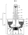
- FIG. 2 is a schematic cross-sectional view showing an example of a structure of an EBM method powder additive manufacturing apparatus and an additive manufacturing method.
- the EBM powder additive manufacturing apparatus 100 is roughly divided into an electron beam control unit 110 and a powder control unit 120, and the whole is a vacuum chamber.
- the stage 121 is lowered by one layer thickness (for example, about 30 to 800 ⁇ m) of the alloy laminate model 230 to be modeled.
- the alloy powder 20 is supplied from the powder hopper 123 onto the base plate 122 on the upper surface of the stage 121, and the alloy powder 20 is flattened by the rake arm 124 to form a powder bed 210 (layered powder) (powder bed forming step).
- Thermoelectrons are emitted from the heated tungsten filament 111 (for example, 2500 ° C. or higher) and accelerated by the anode 112 (for example, about half the speed of light) to form an electron beam 113.
- the accelerated electron beam 113 is rounded by the astigmatism correction device 114 and focused on the powder bed 210 by the focus coil 115.
- a relatively weak (loose) focused beam is scanned by the deflection coil 116 to preheat the entire powder bed 210 to form a temporary sintered body of the powder bed.
- there is an effect that the residual stress of the alloy laminate model is relaxed by the heating in this step, and the deformation of the alloy laminate model 230 is suppressed.
- the calcining temperature of the powder bed 210 is preferably 900 ° C. or higher and 1000 ° C. or lower.
- the calcining temperature is less than 900 ° C., the sintering of the alloy powder particles hardly progresses, and it becomes difficult to form a calcined body.
- the calcining temperature exceeds 1000 ° C., the sintering between the alloy powders proceeds too much, and it becomes difficult to take out the alloy laminated shaped body 230 (separation between the alloy laminated shaped body 230 and the temporary sintered body). .
- the presintered body of the powder bed is irradiated with a strong focused beam for local melting and alloyed
- a 2D slice-shaped solidified layer 220 is formed by scanning the focused beam and moving and sequentially solidifying the fine molten pool (local melting / solidified layer forming step).
- an extraction step of taking out the alloy layered model 230 is performed next.
- the method for taking out the alloy laminate model 230 the separation method between the alloy laminate model 230 and the temporary sintered body, the separation method between the alloy laminate model 230 and the base plate 122
- the conventional method can be used.
- sand blasting using the alloy powder 20 can be preferably used. Sandblasting using the alloy powder 20 has an advantage that it can be reused as the alloy powder 20 by crushing together with the alloy powder 20 sprayed with the removed pre-sintered body.
- the parent phase of the alloy laminate model 230 has a structure in which fine columnar crystals (average particle size of 100 ⁇ m or less) are forested along the lamination direction of the alloy laminate model 230 (so-called rapid solidification structure). It was. Further observation of the alloy laminate model 230 shows that the intermetallic compound phase (mainly Ni 3 Ti phase) needle-like crystals are dispersed and precipitated in a three-dimensional lattice pattern in the matrix crystal. Observed.
- pseudo-solution heat treatment process a pseudo-solution heat treatment is performed on the above-described alloy laminate shaped body 230 so that the intermetallic compound phase of the needle-like crystals is almost completely in solution (referred to as pseudo-solution formation in the present invention).
- the temperature of this heat treatment is preferably in the range of 950 to 1180 ° C, more preferably 1000 to 1150 ° C, and still more preferably 1050 to 1120 ° C.
- the heating atmosphere there is no particular limitation on the heating atmosphere, and it may be in the air or a non-oxidizing atmosphere (an atmosphere in which substantially no oxygen exists, for example, in a vacuum or high-purity argon).
- the sample is kept in the temperature range for an appropriate time and then rapidly cooled (for example, air cooling or water cooling).
- rapidly cooled for example, air cooling or water cooling.
- a temperature range for example, a temperature range of 900 to 800 ° C.
- the previous intermetallic compound phase tends to reprecipitate and grow grains (for example, cool at a rate of 10 ° C./s or more)
- a pseudo-solution-cast alloy shaped body 231 having a microstructure in which nano-scale microscopic particles are dispersed and precipitated in a matrix crystal is obtained.
- the average particle size of the ultrafine particles dispersed and precipitated is preferably 40 nm or less, more preferably 1 nm to 30 nm, and further preferably 2 nm to 20 nm.
- the average particle size of the extremely small particles exceeds 40 nm, the mechanical properties are drastically lowered (details will be described later).
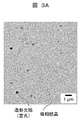
- FIG. 3A is an SEM observation image showing an example of the microstructure of the pseudo-solution-alloyed shaped article according to the present invention.
- FIG. 3B is an SEM observation image showing an example of the microstructure of the alloy laminate model before the pseudo-solution heat treatment.
- the black spot observed in FIG. 3A and FIG. 3B is the defect (modeling defect, for example, void
- TEM transmission electron microscope
- STEM-EDX scanning transmission electron microscope-energy dispersive X-ray spectrometer
- FIG. 4 is a TEM observation result showing an example of the microstructure of the pseudo-solution alloyed shaped body, (a) a bright-field image, (b) an electron diffraction pattern obtained from the field of a, (c) in b (D) a dark field image from the diffraction ring of D2 in b.
- the electron beam diffraction pattern obtained from the field of view in FIG. 4A is a concentric circle such as D2 centered on the diffraction spot such as D1 and the diffraction spot of the transmitted beam.
- a characteristic diffraction pattern with both diffractive rings was shown.
- the diffraction spot in the dark field image from the diffraction spot of D1, since the parent phase is a bright part, the diffraction spot reflects a relatively large parent phase crystal grain. Conceivable. Further, as shown in FIG. 4 (d), it is confirmed that the bright portion having a diameter of about 1 to 10 nm is dispersed in the dark field image from the Debye-Scherrer ring of D2.
- the Debye-Scherrer ring means an assembly of diffraction spots from fine crystal grains (there are a large number of fine crystal grains having random crystal orientations). That is, from these observation results, it was considered that the pseudo-solidified alloy shaped body 231 has a relatively large matrix crystal grain composed of a large number of fine crystal grains.
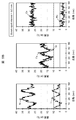
- FIG. 5A is a high-angle scattering annular dark field scanning transmission electron microscope image (HAADF-STEM image) showing an example of the microstructure of the pseudo-solution alloyed shaped article according to the present invention
- FIG. 5B is an analysis in FIG. 5A. It is an EDX ray analysis result on a line.
- FIG. 5A periodic bright and dark (bright / dark) are observed in the HAADF-STEM image.
- the pseudo-solution-alloyed shaped body 231 of the present invention has a microscopic composition modulation structure.
- Ni, Ti, Cr and Fe were modulated in Ni, Ti, Cr and Fe. More specifically, a concentrated region of Ni and Ti (average width of 8 nm) was formed, and in this region, the concentration of Cr and Fe was low (that is, a lightened region of Cr and Fe). ) No clear compositional modulation was observed for Co and Mo. From these facts, Ni and Ti enrichment regions may form crystals of Ni-Ti-Co alloys (Ni-Ti-Co or Ni-Ti-Co-Mo alloys or intermetallic compounds). Sex was suggested.
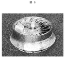
- FIG. 6 is a photograph showing an impeller of a fluid machine as an example of a product using the HEA member according to the present invention. Since the HEA product of the present invention is manufactured by the metal powder additive manufacturing method, even a complicated shape as shown in FIG. 6 can be easily modeled. Further, since the impeller using the HEA member of the present invention has both high mechanical properties and high corrosion resistance, it can exhibit excellent durability even under severe stress / corrosion environments.
- FIG. 7 is a schematic cross-sectional view showing a centrifugal compressor in which the impeller of the present invention is incorporated, which is another example of a product using the HEA member according to the present invention.
- a removal process of removing the temporary sintered body around the alloy additive manufacturing body by sandblasting using HEA powder P1 was performed, and the HEA member M1E of the alloy additive manufacturing body was taken out.
- the HEA member M1E is subjected to pseudo-solution heat treatment (maintained in the air at a temperature range of 950 to 1180 ° C for 3 hours and then rapidly cooled) to form a pseudo-solution-molded HEA member M1E-S.
- pseudo-solution heat treatment maintained in the air at a temperature range of 950 to 1180 ° C for 3 hours and then rapidly cooled
- the sample that has been subjected to water cooling (the average cooling rate at 900 to 800 ° C is about 100 ° C / s) as the rapid cooling method is HEA member M1E-SW, and air cooling (the average cooling rate at 900 to 800 ° C is about 10 ° C / s).
- the sample subjected to s) was designated as HEA member M1E-SA.
- HEA powders P2 to P6 are subjected to the additive manufacturing process, the removal process, and the pseudo-solution heat treatment process in the same manner as described above, and the HEA members M2E-SW, M2E-SA to M6E-SW of the pseudo-solution-forming model body, M6E-SA was produced.
- Example 3 Manufacture of HEA members M1E to M4E for alloy additive manufacturing
- the HEA powders P1 to P4 prepared in Experiment 1 were subjected to the additive manufacturing process and the extraction process in the same manner as described above, thereby producing HEA members M1E to M4E of the alloy additive manufacturing object.
- These alloy layered bodies are samples that have not undergone the pseudo-solution heat treatment step, and serve as reference samples for confirming the influence of the pseudo-solution heat treatment.
- HEA powders P1 to P4 prepared in Experiment 1 were cast by casting an ordinary cast material (14 mm wide x 80 mm long x 15 mm high prism) by arc melting using a copper water-cooled mold. Then, HEA members M1C to M4C of ordinary casting materials were produced. In order to suppress elemental segregation and texture spots during casting as much as possible, dissolution was repeated 5 times or more. These ordinary cast materials are samples that have not been subjected to the additive manufacturing process, and serve as reference samples for confirming the influence of the metal powder additive manufacturing.
- HEA members M1C to M4C of ordinary cast materials are composed of equiaxed crystals with an average grain size of about 900 ⁇ m (however, the crystal grain size is relatively small near the mold) And a structure in which the crystal grain size increases toward the center (so-called cast solidification structure).
- the crystal structure of the equiaxed crystal was a mixture of simple cubic (SC) and face-centered cubic (FCC) (in other words, it clearly contained FCC).
- the matrix structure of HEA members M1E to M4E of the additive manufacturing model has a structure (so-called local rapidly solidified structure) in which fine columnar crystals (average particle size of 100 ⁇ m or less) are forested along the stacking direction of the stacked model. It was. As a result of XRD measurement, the crystal structure of the columnar crystals was almost regarded as consisting of simple cubic crystals (SC).
- the parent phase structure of the HEA member of the pseudo-solution-molded shaped body is composed of equiaxed crystals, but the average particle size was slightly different depending on the quenching method of the pseudo-solution heat treatment and the presence or absence of the aging heat treatment. Specifically, the samples (M1E-SW to M6E-SW) that were water-cooled as a rapid cooling method had an average particle size of the parent phase crystals of about 300 ⁇ m. Samples (M1E-SA to M6E-SA) that were air-cooled as a rapid cooling method had an average particle size of the parent phase crystal of about 500 ⁇ m.
- the average grain size of the parent phase crystal was about 400 ⁇ m.
- the crystal structures of these equiaxed crystals were all considered to consist of simple cubic crystals (SC).
- FIG. 8 is an SEM observation image showing an example of the microstructure of the HEA member M1C of a normal cast material.
- FIG. 3B shown above is an SEM observation image showing an example of the microstructure of the HEA member M1E of the alloy laminate model, and
- FIG. 3A shows an example of the microstructure of the HEA member M1E-SW of the pseudo-solution alloy model. It is a SEM observation image. In other HEA members, it was confirmed that a characteristic precipitate structure was exhibited in each of the normal cast material, the alloy layered structure, and the pseudo-solution formed alloy structure.
- the HEA member M1C which is a normal cast material, had acicular crystals aggregated and deposited randomly.
- a Ni 3 Ti phase was detected, and the main precipitate of needle crystals was considered to be a Ni 3 Ti phase.
- the XRD measurement results have not been able completely deny the precipitation of NiTi phase and NiTi 2 phase (in other words, is likely to NiTi phase and NiTi 2 phase is little precipitation).
- the acicular crystals of the main precipitation phase were dispersed and precipitated in a three-dimensional lattice shape.
- the Ni 3 Ti phase was also detected in the XRD measurement.
- the HEA members M4C and M4E produced using HEA powder P4 containing more than 8 atomic percent of Mo component are considered to be ⁇ phase which is an embrittlement phase in addition to Ni 3 Ti phase as the main precipitation phase in XRD measurement. Diffraction peaks were also detected.
- Ni-Ti-Co-based alloy crystals suggesting the possibility of forming Ni-Ti-Co-based alloy crystals (see FIG. 5B).
- Dispersed and precipitated ultrafine particles (Ni-Ti enriched region) showed a slight difference in the average particle size due to the difference in the quenching method of the pseudo-solution heat treatment.
- the samples (M1E-SW to M6E-SW) that were water-cooled as a rapid cooling method had an average particle size of very small particles of about 2 to 20 nm.
- Samples (M1E-SA to M6E-SA) that were air-cooled as a rapid cooling method had an average particle size of very small particles of about 10 to 40 nm.
- FIG. 9 is a surface analysis result by EDX showing an example of the microstructure of the HEA member M1E-SW-A of the pseudo-solution-cast alloy shaped body.
- the HEA member M1E-SW-A is a sample in which an aging heat treatment is added after the pseudo-solution heat treatment for the purpose of coarsening of extremely small particles.
- the presence of a granular Ni—Ti enriched region (Cr—Fe lightened region) was confirmed.
- the average particle size of the region was over 40 nm.
- a polarization test piece (15 mm long ⁇ 15 mm wide ⁇ 2 mm thick) for pitting corrosion test was collected from each HEA member produced above. The pitting corrosion test was performed on each polarization test piece in accordance with JIS G 0577.
- HEA members M1C to M3C which are ordinary cast materials that have not been subjected to additive manufacturing processes, have a tensile strength of less than 1050 MPa and an elongation at break of less than 10%, and have mechanical properties. It was a failure.
- HEA members M1E to M3E which are specimens of the additive manufacturing process that has been subjected to the additive manufacturing process but not subjected to the pseudo-solution heat treatment process, have a tensile strength of 1050 MPa or more, but the elongation at break is less than 10%. The mechanical properties were unacceptable in terms of ductility.
- the mechanical properties of HEA member M1E-SW-A (average particle size of ultrafine particles exceeding 40 ⁇ ⁇ ⁇ nm), in which the ultrafine particles dispersed and precipitated by coarse heat treatment after quasi-solution heat treatment are coarsened, are significantly reduced. did. From this result, it was confirmed that the average particle size of the extremely small particles dispersed and precipitated in the matrix crystal is preferably 40 nm or less.
- HEA members M1E-SW, M1E-SA to M3E-SW, M3E-SA, and M5E-SW, M5E-SA to M6E-SW, M6E of pseudo-solution-alloyed alloy shaped bodies that are embodiments of the present invention -SA exhibited a tensile strength of 1050 MPa or more and an elongation at break of 10% or more, and proved to have good mechanical properties.
- the HEA member of the present invention is considered to have excellent corrosion resistance due to the combination of elements itself (Co—Cr—Fe—Ni—Ti—Mo).
- the HEA member of the pseudo-solidified alloy shaped body which is an example of the present invention exhibited a higher pitting corrosion occurrence potential than other HEA members, it is expected to have higher corrosion resistance.
Landscapes
- Engineering & Computer Science (AREA)
- Chemical & Material Sciences (AREA)
- Mechanical Engineering (AREA)
- Materials Engineering (AREA)
- Manufacturing & Machinery (AREA)
- Organic Chemistry (AREA)
- Metallurgy (AREA)
- Physics & Mathematics (AREA)
- General Engineering & Computer Science (AREA)
- Optics & Photonics (AREA)
- Thermal Sciences (AREA)
- Plasma & Fusion (AREA)
- Powder Metallurgy (AREA)
- Manufacture Of Metal Powder And Suspensions Thereof (AREA)
- Structures Of Non-Positive Displacement Pumps (AREA)
Abstract
Priority Applications (5)
| Application Number | Priority Date | Filing Date | Title |
|---|---|---|---|
| JP2017566508A JP6493568B2 (ja) | 2016-02-09 | 2016-10-25 | 合金部材、該合金部材の製造方法、および該合金部材を用いた製造物 |
| SG11201806759SA SG11201806759SA (en) | 2016-02-09 | 2016-10-25 | Alloy article, method for manufacturing same, and product using same |
| US16/076,764 US11141791B2 (en) | 2016-02-09 | 2016-10-25 | Alloy article, method for manufacturing same, and product using same |
| CN201680081497.1A CN108699643B (zh) | 2016-02-09 | 2016-10-25 | 合金部件、该合金部件的制造方法和使用了该合金部件的制造物 |
| EP16889892.2A EP3415652B1 (fr) | 2016-02-09 | 2016-10-25 | Élément d'alliage, procédé de production dudit élément d'alliage, et produit comprenant ledit élément d'alliage |
Applications Claiming Priority (2)
| Application Number | Priority Date | Filing Date | Title |
|---|---|---|---|
| JP2016-022381 | 2016-02-09 | ||
| JP2016022381 | 2016-02-09 |
Publications (1)
| Publication Number | Publication Date |
|---|---|
| WO2017138191A1 true WO2017138191A1 (fr) | 2017-08-17 |
Family
ID=59563246
Family Applications (1)
| Application Number | Title | Priority Date | Filing Date |
|---|---|---|---|
| PCT/JP2016/081566 Ceased WO2017138191A1 (fr) | 2016-02-09 | 2016-10-25 | Élément d'alliage, procédé de production dudit élément d'alliage, et produit comprenant ledit élément d'alliage |
Country Status (6)
| Country | Link |
|---|---|
| US (1) | US11141791B2 (fr) |
| EP (1) | EP3415652B1 (fr) |
| JP (1) | JP6493568B2 (fr) |
| CN (1) | CN108699643B (fr) |
| SG (1) | SG11201806759SA (fr) |
| WO (1) | WO2017138191A1 (fr) |
Cited By (9)
| Publication number | Priority date | Publication date | Assignee | Title |
|---|---|---|---|---|
| WO2019074059A1 (fr) * | 2017-10-13 | 2019-04-18 | 株式会社日立製作所 | Élément en alliage à base de titane, procédé de production d'élément en alliage à base de titane, et produit dans lequel un élément en alliage à base de titane est utilisé |
| WO2019088157A1 (fr) | 2017-10-31 | 2019-05-09 | 日立金属株式会社 | Matériau d'alliage, produit utilisant ledit matériau d'alliage, et machine hydraulique ayant ledit produit |
| WO2019088158A1 (fr) * | 2017-10-31 | 2019-05-09 | 日立金属株式会社 | Matériau d'alliage, procédé de production dudit matériau d'alliage, produit utilisant ledit matériau d'alliage et machine à fluide possédant ledit produit |
| WO2021054119A1 (fr) * | 2019-09-20 | 2021-03-25 | 日立金属株式会社 | Procédé de production d'élément en alliage et élément en alliage |
| WO2021176910A1 (fr) * | 2020-03-03 | 2021-09-10 | 日立金属株式会社 | Procédé de production d'élément en alliage, élément en alliage, et produit utilisant un élément en alliage |
| WO2022071378A1 (fr) | 2020-09-29 | 2022-04-07 | 日立金属株式会社 | Matériau d'alliage, produit en alliage dans lequel le matériau d'alliage est utilisé et dispositif de machine comprenant le produit en alliage |
| WO2022172995A1 (fr) * | 2021-02-10 | 2022-08-18 | 日立金属株式会社 | Aimant en alliage fer-chrome-cobalt et son procédé de production |
| US11492685B2 (en) | 2017-08-09 | 2022-11-08 | Hitachi Metals, Ltd. | Alloy member, process for producing said alloy member, and product including said alloy member |
| WO2022260044A1 (fr) | 2021-06-08 | 2022-12-15 | 日立金属株式会社 | Matériau d'alliage, produit d'alliage utilisant un matériau d'alliage, et dispositif de machine pourvu d'un produit d'alliage |
Families Citing this family (29)
| Publication number | Priority date | Publication date | Assignee | Title |
|---|---|---|---|---|
| DE102018204593A1 (de) * | 2018-03-27 | 2019-10-02 | Airbus Defence and Space GmbH | Al-& Mg- verträgliches Strahlgut zum Reinigungsstrahlen derselben auf Basis von AlSc-Pulver |
| US10780515B2 (en) | 2018-04-26 | 2020-09-22 | Raytheon Technologies Corporation | Auto-adaptive braze dispensing systems and methods |
| US10522324B1 (en) * | 2018-08-02 | 2019-12-31 | Expresslo Llc | Method of producing lift out specimens for teaching, practice, and training |
| WO2020084166A1 (fr) | 2018-10-26 | 2020-04-30 | Oerlikon Surface Solutions Ag, Pfäffikon | Revêtements pvd à matrice céramique hea à structure de précipité contrôlée |
| CN109957700B (zh) * | 2019-04-12 | 2020-06-16 | 苏州大学 | 激光熔化沉积制造用FeCrCuTiV高熵合金粉末及其制备方法 |
| US11925985B2 (en) * | 2019-06-26 | 2024-03-12 | Hamilton Sundstrand Corporation | Method of making a radial turbine wheel using additive manufacturing |
| US11353117B1 (en) | 2020-01-17 | 2022-06-07 | Vulcan Industrial Holdings, LLC | Valve seat insert system and method |
| US11421679B1 (en) | 2020-06-30 | 2022-08-23 | Vulcan Industrial Holdings, LLC | Packing assembly with threaded sleeve for interaction with an installation tool |
| US11421680B1 (en) | 2020-06-30 | 2022-08-23 | Vulcan Industrial Holdings, LLC | Packing bore wear sleeve retainer system |
| US12049889B2 (en) | 2020-06-30 | 2024-07-30 | Vulcan Industrial Holdings, LLC | Packing bore wear sleeve retainer system |
| US11384756B1 (en) | 2020-08-19 | 2022-07-12 | Vulcan Industrial Holdings, LLC | Composite valve seat system and method |
| USD986928S1 (en) | 2020-08-21 | 2023-05-23 | Vulcan Industrial Holdings, LLC | Fluid end for a pumping system |
| USD980876S1 (en) | 2020-08-21 | 2023-03-14 | Vulcan Industrial Holdings, LLC | Fluid end for a pumping system |
| USD997992S1 (en) | 2020-08-21 | 2023-09-05 | Vulcan Industrial Holdings, LLC | Fluid end for a pumping system |
| US12366245B1 (en) | 2020-08-27 | 2025-07-22 | Vulcan Industrial Holdings, LLC | Connecting rod assembly for reciprocating pump |
| CN112548482A (zh) * | 2020-10-28 | 2021-03-26 | 中国人民解放军空军工程大学航空机务士官学校 | 基于微弧增材的tc4钛合金结构原位增长修复工艺及工具箱 |
| US11391374B1 (en) | 2021-01-14 | 2022-07-19 | Vulcan Industrial Holdings, LLC | Dual ring stuffing box |
| US12055221B2 (en) | 2021-01-14 | 2024-08-06 | Vulcan Industrial Holdings, LLC | Dual ring stuffing box |
| US12292120B1 (en) | 2021-02-23 | 2025-05-06 | Vulcan Industrial Holdings, LLC | System and method for valve assembly |
| US11846356B1 (en) | 2021-08-18 | 2023-12-19 | Vulcan Industrial Holdings, LLC | Self-locking plug |
| US12510164B1 (en) | 2021-08-18 | 2025-12-30 | Vulcan Industrial Holdings, LLC | Sleeved fluid end |
| US12140240B1 (en) | 2022-01-19 | 2024-11-12 | Vulcan Industrial Holdings, LLC | Gradient material structures and methods of forming the same |
| US12297922B1 (en) | 2022-03-04 | 2025-05-13 | Vulcan Industrial Holdings, LLC | Valve seat with embedded structure and related methods |
| CN114875289B (zh) * | 2022-04-11 | 2023-05-26 | 上海交通大学 | 一种耐高温抗辐照高熵合金及其制备方法 |
| US11434900B1 (en) | 2022-04-25 | 2022-09-06 | Vulcan Industrial Holdings, LLC | Spring controlling valve |
| US11920684B1 (en) | 2022-05-17 | 2024-03-05 | Vulcan Industrial Holdings, LLC | Mechanically or hybrid mounted valve seat |
| USD1113987S1 (en) | 2022-05-20 | 2026-02-17 | Vulcan Industrial Holdings, LLC | Header ring for a pumping system |
| USD1061623S1 (en) | 2022-08-03 | 2025-02-11 | Vulcan Industrial Holdings, LLC | Fluid end for a pumping system |
| US12292121B2 (en) | 2023-08-10 | 2025-05-06 | Vulcan Industrial Holdings, LLC | Valve member including cavity, and related assemblies, systems, and methods |
Citations (1)
| Publication number | Priority date | Publication date | Assignee | Title |
|---|---|---|---|---|
| WO2016013498A1 (fr) * | 2014-07-23 | 2016-01-28 | 株式会社日立製作所 | Structure en alliage, et procédé de fabrication de celle-ci |
Family Cites Families (3)
| Publication number | Priority date | Publication date | Assignee | Title |
|---|---|---|---|---|
| JP4190720B2 (ja) | 2000-11-29 | 2008-12-03 | 國立清華大學 | 多元合金 |
| TWI315345B (en) * | 2006-07-28 | 2009-10-01 | Nat Univ Tsing Hua | High-temperature resistant alloys |
| CN104308153B (zh) * | 2014-10-27 | 2016-08-03 | 西安交通大学 | 一种基于选区激光熔化的高熵合金涡轮发动机热端部件的制造方法 |
-
2016
- 2016-10-25 CN CN201680081497.1A patent/CN108699643B/zh active Active
- 2016-10-25 US US16/076,764 patent/US11141791B2/en active Active
- 2016-10-25 EP EP16889892.2A patent/EP3415652B1/fr active Active
- 2016-10-25 SG SG11201806759SA patent/SG11201806759SA/en unknown
- 2016-10-25 JP JP2017566508A patent/JP6493568B2/ja active Active
- 2016-10-25 WO PCT/JP2016/081566 patent/WO2017138191A1/fr not_active Ceased
Patent Citations (1)
| Publication number | Priority date | Publication date | Assignee | Title |
|---|---|---|---|---|
| WO2016013498A1 (fr) * | 2014-07-23 | 2016-01-28 | 株式会社日立製作所 | Structure en alliage, et procédé de fabrication de celle-ci |
Non-Patent Citations (2)
| Title |
|---|
| CHOU Y. L. ET AL.: "Effect of Inhibitors on the Critical Pitting Temperature of the High- Entropy Alloy Co1.5CrFeNi1.5Ti0.5Mo0.1", JOURNAL OF THE ELECTROCHEMICAL SOCIETY, vol. 158, no. 8, 22 June 2011 (2011-06-22), pages C246 - C251, XP055390822, Retrieved from the Internet <URL:doi:10.1149/1.3600348> * |
| See also references of EP3415652A4 * |
Cited By (28)
| Publication number | Priority date | Publication date | Assignee | Title |
|---|---|---|---|---|
| US11492685B2 (en) | 2017-08-09 | 2022-11-08 | Hitachi Metals, Ltd. | Alloy member, process for producing said alloy member, and product including said alloy member |
| WO2019074059A1 (fr) * | 2017-10-13 | 2019-04-18 | 株式会社日立製作所 | Élément en alliage à base de titane, procédé de production d'élément en alliage à base de titane, et produit dans lequel un élément en alliage à base de titane est utilisé |
| EP3705590A4 (fr) * | 2017-10-31 | 2021-03-24 | Hitachi Metals, Ltd. | Matériau d'alliage, produit utilisant ledit matériau d'alliage, et machine hydraulique ayant ledit produit |
| WO2019088157A1 (fr) | 2017-10-31 | 2019-05-09 | 日立金属株式会社 | Matériau d'alliage, produit utilisant ledit matériau d'alliage, et machine hydraulique ayant ledit produit |
| JPWO2019088158A1 (ja) * | 2017-10-31 | 2020-05-28 | 日立金属株式会社 | 合金材、該合金材の製造方法、該合金材を用いた製造物、および該製造物を有する流体機械 |
| JPWO2019088157A1 (ja) * | 2017-10-31 | 2020-05-28 | 日立金属株式会社 | 合金材、該合金材を用いた製造物、および該製造物を有する流体機械 |
| JP2020114948A (ja) * | 2017-10-31 | 2020-07-30 | 日立金属株式会社 | 金属積層造形用混合粉末 |
| WO2019088158A1 (fr) * | 2017-10-31 | 2019-05-09 | 日立金属株式会社 | Matériau d'alliage, procédé de production dudit matériau d'alliage, produit utilisant ledit matériau d'alliage et machine à fluide possédant ledit produit |
| US12000022B2 (en) | 2017-10-31 | 2024-06-04 | Proterial, Ltd. | High entropy alloy article, product formed of said high entropy alloy article, and fluid machine having said product |
| US11359638B2 (en) | 2017-10-31 | 2022-06-14 | Hitachi Metals, Ltd. | Alloy article, method for manufacturing said alloy article, product formed of said alloy article, and fluid machine having said product |
| CN111051551B (zh) * | 2017-10-31 | 2022-10-11 | 日立金属株式会社 | 合金材料、使用该合金材料的制造物、及具有该制造物的流体机械 |
| EP4190933A1 (fr) | 2017-10-31 | 2023-06-07 | Proterial, Ltd. | Poudre d'alliage |
| CN111051551A (zh) * | 2017-10-31 | 2020-04-21 | 日立金属株式会社 | 合金材料、使用该合金材料的制造物、及具有该制造物的流体机械 |
| JP7156474B2 (ja) | 2019-09-20 | 2022-10-19 | 日立金属株式会社 | 合金部材の製造方法 |
| JP2021185272A (ja) * | 2019-09-20 | 2021-12-09 | 日立金属株式会社 | 合金部材の製造方法 |
| JPWO2021054119A1 (ja) * | 2019-09-20 | 2021-09-30 | 日立金属株式会社 | 合金部材の製造方法、および合金部材 |
| JP7156475B2 (ja) | 2019-09-20 | 2022-10-19 | 日立金属株式会社 | 合金部材 |
| US12330215B2 (en) | 2019-09-20 | 2025-06-17 | Proterial, Ltd. | Alloy member production method and alloy member |
| JP2021185273A (ja) * | 2019-09-20 | 2021-12-09 | 日立金属株式会社 | 合金部材 |
| WO2021054119A1 (fr) * | 2019-09-20 | 2021-03-25 | 日立金属株式会社 | Procédé de production d'élément en alliage et élément en alliage |
| JP7173397B2 (ja) | 2020-03-03 | 2022-11-16 | 日立金属株式会社 | 合金部材の製造方法、合金部材、および合金部材を用いた製造物 |
| JPWO2021176910A1 (fr) * | 2020-03-03 | 2021-09-10 | ||
| WO2021176910A1 (fr) * | 2020-03-03 | 2021-09-10 | 日立金属株式会社 | Procédé de production d'élément en alliage, élément en alliage, et produit utilisant un élément en alliage |
| WO2022071378A1 (fr) | 2020-09-29 | 2022-04-07 | 日立金属株式会社 | Matériau d'alliage, produit en alliage dans lequel le matériau d'alliage est utilisé et dispositif de machine comprenant le produit en alliage |
| WO2022172995A1 (fr) * | 2021-02-10 | 2022-08-18 | 日立金属株式会社 | Aimant en alliage fer-chrome-cobalt et son procédé de production |
| JP7524979B2 (ja) | 2021-02-10 | 2024-07-30 | 株式会社プロテリアル | 鉄-クロム-コバルト系合金磁石およびその製造方法 |
| JPWO2022172995A1 (fr) * | 2021-02-10 | 2022-08-18 | ||
| WO2022260044A1 (fr) | 2021-06-08 | 2022-12-15 | 日立金属株式会社 | Matériau d'alliage, produit d'alliage utilisant un matériau d'alliage, et dispositif de machine pourvu d'un produit d'alliage |
Also Published As
| Publication number | Publication date |
|---|---|
| CN108699643B (zh) | 2020-06-23 |
| EP3415652A1 (fr) | 2018-12-19 |
| US20190047049A1 (en) | 2019-02-14 |
| JP6493568B2 (ja) | 2019-04-03 |
| JPWO2017138191A1 (ja) | 2018-12-27 |
| SG11201806759SA (en) | 2018-09-27 |
| US11141791B2 (en) | 2021-10-12 |
| EP3415652A4 (fr) | 2019-08-21 |
| EP3415652B1 (fr) | 2021-03-24 |
| CN108699643A (zh) | 2018-10-23 |
Similar Documents
| Publication | Publication Date | Title |
|---|---|---|
| JP6493568B2 (ja) | 合金部材、該合金部材の製造方法、および該合金部材を用いた製造物 | |
| JP6835139B2 (ja) | 合金部材の製造方法 | |
| JP6493561B2 (ja) | ハイエントロピー合金部材、該合金部材の製造方法、および該合金部材を用いた製造物 | |
| JP6937491B2 (ja) | 合金部材、該合金部材の製造方法、および該合金部材を用いた製造物 | |
| US12000022B2 (en) | High entropy alloy article, product formed of said high entropy alloy article, and fluid machine having said product | |
| US11359638B2 (en) | Alloy article, method for manufacturing said alloy article, product formed of said alloy article, and fluid machine having said product | |
| US20240076763A1 (en) | Heat-resistant alloy, heat-resistant alloy powder, heat-resistant alloy structural component, and manufacturing method of the same | |
| JP7156475B2 (ja) | 合金部材 | |
| JP7311053B2 (ja) | 合金材料、該合金材料を用いた合金製造物、および該合金製造物を有する機械装置 |
Legal Events
| Date | Code | Title | Description |
|---|---|---|---|
| 121 | Ep: the epo has been informed by wipo that ep was designated in this application |
Ref document number: 16889892 Country of ref document: EP Kind code of ref document: A1 |
|
| WWE | Wipo information: entry into national phase |
Ref document number: 2017566508 Country of ref document: JP |
|
| WWE | Wipo information: entry into national phase |
Ref document number: 11201806759S Country of ref document: SG |
|
| NENP | Non-entry into the national phase |
Ref country code: DE |
|
| WWE | Wipo information: entry into national phase |
Ref document number: 2016889892 Country of ref document: EP |
|
| ENP | Entry into the national phase |
Ref document number: 2016889892 Country of ref document: EP Effective date: 20180910 |