WO2017138351A1 - Structure de fixation d'élément d'insert pour matériau de coussin - Google Patents
Structure de fixation d'élément d'insert pour matériau de coussin Download PDFInfo
- Publication number
- WO2017138351A1 WO2017138351A1 PCT/JP2017/002445 JP2017002445W WO2017138351A1 WO 2017138351 A1 WO2017138351 A1 WO 2017138351A1 JP 2017002445 W JP2017002445 W JP 2017002445W WO 2017138351 A1 WO2017138351 A1 WO 2017138351A1
- Authority
- WO
- WIPO (PCT)
- Prior art keywords
- insert
- cushion material
- fixing structure
- wire
- cushion
- Prior art date
- Legal status (The legal status is an assumption and is not a legal conclusion. Google has not performed a legal analysis and makes no representation as to the accuracy of the status listed.)
- Ceased
Links
Images


Classifications
-
- A—HUMAN NECESSITIES
- A47—FURNITURE; DOMESTIC ARTICLES OR APPLIANCES; COFFEE MILLS; SPICE MILLS; SUCTION CLEANERS IN GENERAL
- A47C—CHAIRS; SOFAS; BEDS
- A47C27/00—Spring, stuffed or fluid mattresses or cushions specially adapted for chairs, beds or sofas
- A47C27/14—Spring, stuffed or fluid mattresses or cushions specially adapted for chairs, beds or sofas with foamed material inlays
-
- A—HUMAN NECESSITIES
- A47—FURNITURE; DOMESTIC ARTICLES OR APPLIANCES; COFFEE MILLS; SPICE MILLS; SUCTION CLEANERS IN GENERAL
- A47C—CHAIRS; SOFAS; BEDS
- A47C31/00—Details or accessories for chairs, beds, or the like, not provided for in other groups of this subclass, e.g. upholstery fasteners, mattress protectors, stretching devices for mattress nets
- A47C31/02—Upholstery attaching means
-
- B—PERFORMING OPERATIONS; TRANSPORTING
- B68—SADDLERY; UPHOLSTERY
- B68G—METHODS, EQUIPMENT, OR MACHINES FOR USE IN UPHOLSTERING; UPHOLSTERY NOT OTHERWISE PROVIDED FOR
- B68G7/00—Making upholstery
- B68G7/05—Covering or enveloping cores of pads
- B68G7/052—Covering or enveloping cores of pads with webs secured to the core, e.g. by stitching
Definitions
- the present invention relates to an insert member fixing structure for a cushion material.
- an insert wire for trim cover suspension is integrally foamed and held in the cushion material.
- An object of the present invention is to provide an insert member fixing structure of a cushion material having a structure in which an insert member such as an insert wire is difficult to be removed from the cushion material.
- the present invention is a structure for fixing to the cushion material an insert member used to suspend and support the skin on the foam cushion material, It further includes an anchor member attached to the insert member and at least a part of which is located inside the cushion material.
- the anchor member improves the pulling strength of the insert member such as an insert wire. This makes it difficult for the insert member to come off the cushion material.
- the present invention is a structure for fixing to the cushion material an insert member used to suspend and support a trim cover serving as a skin for the foam cushion material constituting the seat member, It further includes an anchor member attached to a part of the insert member and at least a part of which is located inside the cushion material.
- the anchor member improves the pulling strength of the insert member such as an insert wire. Thereby, it becomes difficult for the insert member in the seat to come off from the cushion material.
- the insert member is, for example, an insert wire.
- the anchor member may be a non-woven fabric.
- the anchor member may be arranged in a direction orthogonal to the insert wire.
- the anchor member may be spread in a direction orthogonal to the direction of the tensile force received when the insert wire suspends and supports the skin.
- the anchor member may be attached to an end portion of the insert wire.
- the anchor member may be arranged at a position near the surface of the cushion material of the insert wire.
- the insert wire may be inserted through the anchor member.
- the anchor member may be tied to the insert wire.
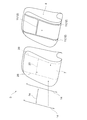
- FIG. 1 It is a perspective view which shows an example of a sheet
- FIG. 6 is a cross-sectional view showing an insert member fixing structure (corresponding to a second embodiment) taken along line X (XI) -X (XI) in FIG. 5.
- FIG. 6 is a cross-sectional view showing an insert member fixing structure (corresponding to a third embodiment) taken along line X (XI) -X (XI) in FIG. 5.
- the seat 1 includes a seat 2 that can move back and forth on the floor panel of the vehicle, and a backrest 3 that can be reclined with respect to the seat 2.
- Each of the seat 2 and the backrest 3 is a seat member constituting the seat 1 and includes a cushion material 4 made of a foam.
- the trim cover 7 can be attached to and detached from the seat 2 and the backrest 3 by using the suspension structure 10.
- the cushion material 4 constituting the backrest 3 has a main cushion portion 41 for supporting the occupant's back from the rear and a side cushion portion 42 for holding the occupant's back from the side (see FIG. 3). ).
- the trim cover 7 includes a main surface portion 71 placed on the main cushion portion 41 of the cushion material 4 and a part of the side cushion portion 42, a side surface portion 72 placed on the remaining portion of the side cushion portion 42, Is formed by.
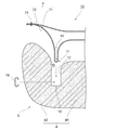
- the main surface portion 71 and the side surface portion 72 of the trim cover 7 are joined together by a stitching portion 74 in a state where the surfaces of the trim cover 7 are in contact with each other, and the front surface faces the seated person and the back surface faces the cushion material 4 side. 4, the stitched portion 74 and the portion of the trim cover 7 beyond the stitched portion 74 are not exposed to the surface side (see FIGS. 3 and 4).
- the suspension structure 10 includes a suspension groove 11, a linear suspension member 14, an insert wire 16, and a hog ring 18 (see FIG. 3 and the like).
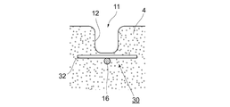
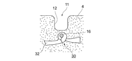
- the hanging groove 11 is composed of a recess 12 formed at a predetermined depth in the longitudinal direction of the backrest 2 along the boundary portion between the main cushion portion 41 and the side cushion portion 42, and forms the appearance of the seat 1. .
- the recess 12 is pressed and closed between the main cushion portion 41 and the side cushion portion 42 by the elasticity of the cushion material 4, but for the sake of convenience, in FIG. 3 and FIG.
- the recessed part 12 of the state which showed is shown.
- the backrest 3 is further provided with a hanging groove 11 extending along the lateral method (width direction of the backrest 3) in addition to the above-described hanging groove 11, and the seat 2 is also provided with the hanging groove 11.
- the description will be continued by taking the hanging groove 11 formed of the concave portion 12 formed in the vertical direction as described above as an example.
- the insert wire 16 is partially embedded in the cushion material 4 of the backrest 3 and in a portion deeper than the bottom of the recess 12 by a predetermined amount (see FIG. 3. In FIG. 3, the groove depth of the recess 12. The direction is represented by the symbol D).
- the predetermined amount here is an amount suitable for fastening in consideration of the size of the hog ring 18 and the like when fastening the linear suspension member 14 and the insert wire 16 with the hog ring 18 (see FIG. 4). ).
- the insert wire 16 has a direction in which the recess 12 is formed (in this embodiment, a boundary portion between the main cushion portion 41 and the side cushion portion 42).
- the wire may extend straight in the longitudinal direction), or may be a wire in which the portion to which the hog ring 18 is fastened is bent in a crank shape toward the recess 12.
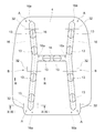
- the longitudinal direction one end or both ends of the insert wire 16 may be rounded (refer FIG. 5).
- deeper deep groove portions (skin suspending portions) 13 may be formed at a plurality of locations along the direction in which the recess 12 is formed (see FIG. 5).
- the insert wire 16 embedded in the cushion material 4 is in a state of being exposed from the cushion material 4 in the deep groove portion 13, and the hog ring 18 can be easily fastened to the insert wire 16. .
- the linear suspension member 14 is disposed on the surface of the trim cover 7 (the surface on the side opposite to the cushion material 4 and serving as a skin on which the seated person touches the seat 1), and is suspended with a part of the trim cover 7. A member that is inserted into the groove 11 and suspends the trim cover 7.
- the linear suspension member 14 may be made of metal such as iron or aluminum, may be made of resin such as polypropylene or polyethylene, or may be made of rubber. Both ends of the linear suspension member 14 formed of a linear wire are rounded so as to be easy to handle during work and difficult to move in the longitudinal direction inside the suspension groove 11 (see FIG. 2). .
- the hog ring 18 fastens the linear suspension member 14 inserted into the suspension groove 11 to the sheet member.
- the hog ring 18 can be easily fastened to a predetermined position in the hanging groove 11 by using a dedicated tool (hog ring fastening device).
- the hog ring 18 is substantially C-shaped, and one end penetrates the trim cover 7 from the back side and is hooked on the linear suspension member 14, and the other end is thrust into the cushion material 4 and hooked on the insert wire 16, or a deep groove portion. 13 is hooked on the insert wire 16 and is deformed by being pressed and fastened together (see FIGS. 3 and 4).
- the hog ring 18 is only a suitable example of a fastening member that fastens the linear suspension member 14 and the insert wire 16, and other than this, a C-shaped ring or other various fastening tools can be used.
- an insert wire fixing structure 30 for fixing the insert wire 16 to the cushion material 4 will be described (see FIGS. 5 to 11).
- the insert wire fixing structure 30 is a structure for fixing the insert wire 16 used to suspend and support the trim cover 7 to the cushion material 4 to the cushion material 4.
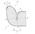
- the insert wire fixing structure 30 of this embodiment further includes a nonwoven fabric 32.
- the nonwoven fabric 32 is attached to the insert wire 16 so that at least a part thereof is located inside the cushion material 4 (see FIG. 8 and the like).
- the nonwoven fabric 32 is one of urethane-impregnated members, foamed so as to impregnate the urethane constituting the cushion material 4, and at least a part of the nonwoven fabric 32 is positioned inside the cushion material 4 to contact the cushion material 4.
- By increasing the area it functions as an anchor that disperses the pressure and increases the pull-out resistance from the cushion material 4.
- the nonwoven fabric 32 is lightweight and inexpensive, and is one of materials suitable as an anchor member.
- the insert wire fixing structure 30 including the non-woven fabric 32 it is possible to improve the pull-out strength at the end of the insert wire 16, which is a particularly weak portion (see the portion represented by symbol A in FIG. 5). Of course, it is possible to improve the pull-out strength not only at the end portion but also at the intermediate portion of the insert wire 16 (see the portion indicated by symbol B in FIG. 5).
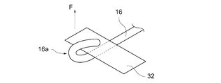
- FIG. 6 shows an example in which the nonwoven fabric 32 is attached to the front surface side (close to the surface) of the cushion material 4 when viewed from the insert wire 16.
- the nonwoven fabric 32 functions as an anchor that makes it difficult to pull out the insert wire 16 inside the cushion material 4 (see FIG. 10).
- the nonwoven fabric 32 may be sandwiched and fixed by the bent portion 16a (see FIG. 6).
- the non-woven fabric 32 is arranged in a direction orthogonal to the insert wire 16 (direction of the cross section of the wire) (see FIGS. 6 and 10), and according to this, otherwise (for example, the axial direction of the insert wire 16)
- the resistance in the cushioning material 4 is increased as compared with the case where it is arranged so as to extend along the vertical axis, and the pull-out strength can be further improved.
- the trim cover 7 can be suspended and supported by fastening the hog ring 18 to a portion of the insert wire 16 exposed on the surface of the cushion material 4 (see FIGS. 4 and 9).
- the direction of the tensile force F received by the suspended insert wire 16 is represented by an upward arrow in FIG. 6 (and also in FIGS. 7 and 8)
- the nonwoven fabric 32 is orthogonal to the direction of the tensile force F. It is preferable to spread in the direction (see FIG. 6 and the like). According to this, the resistance to the tensile force F can be further increased and the pulling strength can be improved.
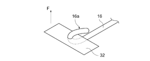
- the insert wire 16 may be inserted through the nonwoven fabric 32 (see FIG. 7). Also in this case, the nonwoven fabric 32 is preferably arranged in a direction orthogonal to the insert wire 16 and preferably spread in a direction orthogonal to the direction of the tensile force F.
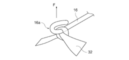
- the non-woven fabric 32 may be connected to the insert wire 16 (see FIGS. 8 and 11). Also in this case, the nonwoven fabric 32 is preferably arranged in a direction orthogonal to the insert wire 16 and preferably spread in a direction orthogonal to the direction of the tensile force F.
- the linear suspension member 14 is disposed at a predetermined position on the surface side of the trim cover 7 while using the marking 20 as a mark (see FIGS. 2 and 3). Thereafter, the linear suspension member 14 is inserted into the suspension groove 11 while being wrapped in the trim cover 7 (see FIG. 3).
- the hog ring fastening device (not shown) is used to fasten the linear suspension member 14 and the insert wire 16 with the hog ring 18 (see FIGS. 3 and 4). Similarly, the linear suspension member 14 and the insert wire 16 are fastened by the hog ring 18 at other predetermined locations. As described above, the linear suspension member 14 is fastened to the backrest 3 together with a part of the trim cover 7, and the suspension operation is completed.
- the insert wire 16 has been described as an example, but this is only a suitable example of an insert member partially embedded in the cushion material 4.
- non-woven fabric 32 described in the above embodiment is merely a suitable example of an anchor member, and it goes without saying that various members can be used as the anchor member.
- the seat 1 includes various seats such as an automobile seat, an airplane seat, a passenger ship seat, a stroller, and a child seat. Things are included.
- the present invention is applied to the seat 1, but the present invention can also be applied to other than the seat 1 including the cushion material 4.
- the provision of the insert member such as the insert wire 16 in the cushion material 4 can alleviate local deformation of the cushion material 4 and make the hog ring 18 difficult to move or come off.
- the insert member may not necessarily be provided as long as the hog ring 18 can be firmly fastened only by the cushion material 4.
- the present invention is suitable for application to a structure for fixing an insert member used to suspend and support an epidermis to a foam cushion material to the cushion material.
Landscapes
- Engineering & Computer Science (AREA)
- Textile Engineering (AREA)
- Manufacturing & Machinery (AREA)
- Mechanical Engineering (AREA)
- Seats For Vehicles (AREA)
- Mattresses And Other Support Structures For Chairs And Beds (AREA)
Abstract
L'invention concerne une structure de fixation d'élément d'insert qui est une structure pour fixer, dans un matériau de coussin en mousse (4) qui constitue une partie d'un élément de siège, un élément d'insert (16) utilisé pour soutenir de manière suspendue un revêtement de garniture qui est une enveloppe pour le matériau de coussin (4), la structure étant fixée à une partie de l'élément d'insert (16), et au moins une partie de la structure comprenant en outre un élément d'ancrage (32) positionné à l'intérieur du matériau de coussin (4). L'élément d'insert (16) est, par exemple, un fil d'insert. L'élément d'ancrage (32) peut comprendre un non-tissé.
Applications Claiming Priority (2)
| Application Number | Priority Date | Filing Date | Title |
|---|---|---|---|
| JP2016022008A JP2017140099A (ja) | 2016-02-08 | 2016-02-08 | クッション材のインサート部材固定構造 |
| JP2016-022008 | 2016-02-08 |
Publications (1)
| Publication Number | Publication Date |
|---|---|
| WO2017138351A1 true WO2017138351A1 (fr) | 2017-08-17 |
Family
ID=59563159
Family Applications (1)
| Application Number | Title | Priority Date | Filing Date |
|---|---|---|---|
| PCT/JP2017/002445 Ceased WO2017138351A1 (fr) | 2016-02-08 | 2017-01-25 | Structure de fixation d'élément d'insert pour matériau de coussin |
Country Status (2)
| Country | Link |
|---|---|
| JP (1) | JP2017140099A (fr) |
| WO (1) | WO2017138351A1 (fr) |
Citations (5)
| Publication number | Priority date | Publication date | Assignee | Title |
|---|---|---|---|---|
| JPS6088899U (ja) * | 1983-11-25 | 1985-06-18 | (株)タチエス | 車輌用の座席 |
| JPS6292798U (fr) * | 1985-11-30 | 1987-06-13 | ||
| JPH0213430U (fr) * | 1988-07-12 | 1990-01-26 | ||
| JPH11276735A (ja) * | 1998-03-31 | 1999-10-12 | Ikeda Bussan Co Ltd | 車両用シートのカバー取付構造 |
| JP2011078452A (ja) * | 2009-10-02 | 2011-04-21 | Toyo Tire & Rubber Co Ltd | 車両用シートパッド |
-
2016
- 2016-02-08 JP JP2016022008A patent/JP2017140099A/ja active Pending
-
2017
- 2017-01-25 WO PCT/JP2017/002445 patent/WO2017138351A1/fr not_active Ceased
Patent Citations (5)
| Publication number | Priority date | Publication date | Assignee | Title |
|---|---|---|---|---|
| JPS6088899U (ja) * | 1983-11-25 | 1985-06-18 | (株)タチエス | 車輌用の座席 |
| JPS6292798U (fr) * | 1985-11-30 | 1987-06-13 | ||
| JPH0213430U (fr) * | 1988-07-12 | 1990-01-26 | ||
| JPH11276735A (ja) * | 1998-03-31 | 1999-10-12 | Ikeda Bussan Co Ltd | 車両用シートのカバー取付構造 |
| JP2011078452A (ja) * | 2009-10-02 | 2011-04-21 | Toyo Tire & Rubber Co Ltd | 車両用シートパッド |
Also Published As
| Publication number | Publication date |
|---|---|
| JP2017140099A (ja) | 2017-08-17 |
Similar Documents
| Publication | Publication Date | Title |
|---|---|---|
| US8157324B2 (en) | Cover material terminal treating member, seat part, and vehicle seat | |
| JP6276042B2 (ja) | 乗物用シート | |
| JP6636263B2 (ja) | シート | |
| JP6703809B2 (ja) | シートの吊り込み構造およびシートにおけるトリムカバーの吊り込み方法 | |
| JP2016087196A (ja) | 乗物用シート | |
| JP2017018561A (ja) | シートの吊り込み構造 | |
| CN111469730A (zh) | 用于模块化车辆座椅等的车辆座椅衬垫托架组件 | |
| US20170088027A1 (en) | Vehicle seat | |
| JP6292100B2 (ja) | 乗物用シート | |
| JP6639333B2 (ja) | 車両用シート | |
| JP6265881B2 (ja) | シート | |
| JP5890876B1 (ja) | サイドサポートカバーの取付構造 | |
| WO2017138351A1 (fr) | Structure de fixation d'élément d'insert pour matériau de coussin | |
| JP5917317B2 (ja) | 自動車シートに用いるシート・バック | |
| US10358064B2 (en) | Headrest cover | |
| JP6275777B2 (ja) | 車両用シート | |
| JP2019062994A (ja) | 車両用シート構造 | |
| JP5528676B2 (ja) | 車両用シート | |
| JP2022147823A (ja) | 乗物用シート及び乗物用シートの製造方法 | |
| JP4745413B2 (ja) | シート製造方法およびシート構造 | |
| JP5989409B2 (ja) | 自動車シートに用いるアームレスト | |
| WO2017188000A1 (fr) | Structure d'accrochage de siège, housse de siège, et siège | |
| CN113840796A (zh) | 座椅 | |
| JP2007236460A (ja) | シートパッド及びクッション材 | |
| JP2017081362A (ja) | 車両用シート及びその製造方法 |
Legal Events
| Date | Code | Title | Description |
|---|---|---|---|
| 121 | Ep: the epo has been informed by wipo that ep was designated in this application |
Ref document number: 17750076 Country of ref document: EP Kind code of ref document: A1 |
|
| NENP | Non-entry into the national phase |
Ref country code: DE |
|
| 122 | Ep: pct application non-entry in european phase |
Ref document number: 17750076 Country of ref document: EP Kind code of ref document: A1 |