WO2017138657A1 - Article moulé à bord d'un véhicule - Google Patents
Article moulé à bord d'un véhicule Download PDFInfo
- Publication number
- WO2017138657A1 WO2017138657A1 PCT/JP2017/005004 JP2017005004W WO2017138657A1 WO 2017138657 A1 WO2017138657 A1 WO 2017138657A1 JP 2017005004 W JP2017005004 W JP 2017005004W WO 2017138657 A1 WO2017138657 A1 WO 2017138657A1
- Authority
- WO
- WIPO (PCT)
- Prior art keywords
- vehicle
- aluminum substrate
- resin
- molded article
- molded product
- Prior art date
- Legal status (The legal status is an assumption and is not a legal conclusion. Google has not performed a legal analysis and makes no representation as to the accuracy of the status listed.)
- Ceased
Links
Images







Classifications
-
- B—PERFORMING OPERATIONS; TRANSPORTING
- B60—VEHICLES IN GENERAL
- B60K—ARRANGEMENT OR MOUNTING OF PROPULSION UNITS OR OF TRANSMISSIONS IN VEHICLES; ARRANGEMENT OR MOUNTING OF PLURAL DIVERSE PRIME-MOVERS IN VEHICLES; AUXILIARY DRIVES FOR VEHICLES; INSTRUMENTATION OR DASHBOARDS FOR VEHICLES; ARRANGEMENTS IN CONNECTION WITH COOLING, AIR INTAKE, GAS EXHAUST OR FUEL SUPPLY OF PROPULSION UNITS IN VEHICLES
- B60K35/00—Instruments specially adapted for vehicles; Arrangement of instruments in or on vehicles
- B60K35/20—Output arrangements, i.e. from vehicle to user, associated with vehicle functions or specially adapted therefor
- B60K35/21—Output arrangements, i.e. from vehicle to user, associated with vehicle functions or specially adapted therefor using visual output, e.g. blinking lights or matrix displays
- B60K35/212—Output arrangements, i.e. from vehicle to user, associated with vehicle functions or specially adapted therefor using visual output, e.g. blinking lights or matrix displays displaying on manual operation elements, e.g. on a knob
-
- B—PERFORMING OPERATIONS; TRANSPORTING
- B29—WORKING OF PLASTICS; WORKING OF SUBSTANCES IN A PLASTIC STATE IN GENERAL
- B29C—SHAPING OR JOINING OF PLASTICS; SHAPING OF MATERIAL IN A PLASTIC STATE, NOT OTHERWISE PROVIDED FOR; AFTER-TREATMENT OF THE SHAPED PRODUCTS, e.g. REPAIRING
- B29C45/00—Injection moulding, i.e. forcing the required volume of moulding material through a nozzle into a closed mould; Apparatus therefor
- B29C45/14—Injection moulding, i.e. forcing the required volume of moulding material through a nozzle into a closed mould; Apparatus therefor incorporating preformed parts or layers, e.g. injection moulding around inserts or for coating articles
-
- C—CHEMISTRY; METALLURGY
- C23—COATING METALLIC MATERIAL; COATING MATERIAL WITH METALLIC MATERIAL; CHEMICAL SURFACE TREATMENT; DIFFUSION TREATMENT OF METALLIC MATERIAL; COATING BY VACUUM EVAPORATION, BY SPUTTERING, BY ION IMPLANTATION OR BY CHEMICAL VAPOUR DEPOSITION, IN GENERAL; INHIBITING CORROSION OF METALLIC MATERIAL OR INCRUSTATION IN GENERAL
- C23F—NON-MECHANICAL REMOVAL OF METALLIC MATERIAL FROM SURFACE; INHIBITING CORROSION OF METALLIC MATERIAL OR INCRUSTATION IN GENERAL; MULTI-STEP PROCESSES FOR SURFACE TREATMENT OF METALLIC MATERIAL INVOLVING AT LEAST ONE PROCESS PROVIDED FOR IN CLASS C23 AND AT LEAST ONE PROCESS COVERED BY SUBCLASS C21D OR C22F OR CLASS C25
- C23F1/00—Etching metallic material by chemical means
- C23F1/02—Local etching
Definitions
- the present invention relates to an in-vehicle molded product.
- Japanese Unexamined Patent Publication No. 2000-199082 discloses a technique relating to carving and forming an aluminum thin plate.
- an image is formed on the first surface by performing an etching process from the first surface to the second surface of the thin plate, and after an etching process, an anodic oxide film is formed on the etching end surface of the aluminum thin plate.
- Techniques for manufacturing engraved molded products are disclosed.
- An object of the present invention is to provide a technique capable of further improving the visibility of symbols and the like displayed on an in-vehicle molded product, as compared with the processing method for engraved molded products in the above technique.
- the in-vehicle molded article according to the present invention has a metal plate material and a resin material, and for example, an in-vehicle panel for displaying numbers, characters, designs, etc. of a speedometer of a vehicle, an in-vehicle panel such as an engine starter or a power window It can be used for operation switches.
- a metal plate material for example, an aluminum substrate can be preferably used, or stainless steel, copper, nickel, nichrome, titanium, or an alloy substrate by appropriate selection thereof can be used.
- the material of the resin material for example, PMMA (acrylic), PC (polycarbonate), PET (polyethylene terephthalate), PVC (vinyl chloride resin), or the like can be adopted.
- the metal plate material has a first surface and a second surface formed in an opposing manner, and a resin material is disposed on the first surface, and a second surface is disposed on the second surface.
- a predetermined symbol is arranged. This symbol is used as visual information toward the vehicle occupant, and is formed on the second surface through a recess formed through the metal plate material from the first surface to the second surface.
- the 2nd surface of a metal plate material will be set as a design surface which a passenger
- it is comprised so that the opening edge part in the 2nd surface of the said recessed part may become an acute angle. Therefore, the pattern formed on the second surface has a sharp outline due to the opening end of the recess having an acute angle, and high visibility to the occupant can be ensured.
- the first surface of the metal plate material when a pattern or the like is formed on a metal plate material by an etching process, particularly when etching is performed so as to penetrate the metal plate material by an isotropic etching process, typically, the first surface of the metal plate material
- the shape of the recess formed by etching differs from the second surface. If the first surface, which is the surface on the etching start side, is set as a design surface for the occupant, the inner wall surface of the penetrating recess due to the etching process is exposed to the occupant side due to undercut or the like due to etching. , The design may look bad.
- the metal plate is formed from the first surface to the second surface through the metal plate material, and the opposite end of the first surface is provided through the concave portion in which the opening end of the second surface is formed at an acute angle.
- the second surface as a design surface, the inner surface of the recess is prevented from being exposed from the second surface to the occupant side as much as possible, and the contour of the design formed on the second surface, which is the design surface, is emphasized. Stand up, improve appearance, and improve the visibility of symbols.
- An in-vehicle molded article according to the present invention includes, for example, an etching process step of performing an etching process from the first surface of the metal plate material to the second surface so as to penetrate the metal plate material, and the first surface of the metal plate material. It can manufacture through the resin material arrangement
- the concave portion as an etching processing portion.
- the opening end portion on the second surface of the recess corresponds to the design dimension of the design, and the opening end portion area on the second surface is smaller than the opening end portion area on the first surface.
- the resin material is further configured to have a colored ink layer.
- the colored ink layer is an embodiment using the resin material itself, an embodiment in which an ink layer different from the resin material is prepared and laminated on the resin material, an embodiment in which a colored region is partly or entirely, a plurality of colored patterns A mode in which the change is applied, a mode in which a gradation change (gradation) is performed in a single color, and the like can be appropriately employed.
- the resin material it is also preferable to control the amount of light passing through the concave portion from the first surface to the second surface by adjusting the resin material to be transparent or translucent so as to dimm the design. Thereby, the visibility of a symbol can further be improved.
- the resin material it is good also as a structure which has a resin molded product relevant to a vehicle-mounted product, and the resin film interposed between the said resin molded product and a metal plate. Since the resin film is interposed, the integral formation of the resin molded product and the metal plate is further rationalized.
- the resin molded product and the resin film may adopt various forms relating to coloring, such as an aspect configured with the same color, an aspect configured with different colors, and an aspect configured with the same color but different brightness.
- FIGS. A typical embodiment of the present invention will be described with reference to FIGS.
- This embodiment demonstrates the symbol display molded product 100 as a vehicle-mounted panel used for a vehicle speedometer etc. as an example of vehicle-mounted molded products.
- the symbol display molded article 100 is a flat plate-mounted component in which numbers, patterns, and the like are visible.
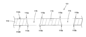
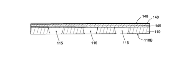
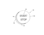
- the symbol display molded article 100 includes a display unit 101 such as numerals and patterns formed by etching the aluminum substrate 110.
- the display unit 101 includes a recess 115 formed by etching, and a non-etched portion 116 surrounded by the recess 115 around the entire periphery.
- the non-etched portion 116 surrounded by the recess 115 is also referred to as a floating island portion or a surrounding portion.
- the display unit 101 is surrounded by a form such as a number or a pattern including only the recess 115 such as the number “1”, and the recess 115 and the recess 115 such as the numbers “8” and “0”. Any form of numbers, patterns, and the like constituted by the non-etching portion 116 is also suitably included.
- the aluminum substrate 110 is isotropic from the first surface 110 ⁇ / b> A (the upper surface in FIG. 3, also referred to as an etching start surface) to the second surface 110 ⁇ / b> B (the lower surface in FIG. 3).
- the dimension (opening end area) of the recess 115 formed by etching on the first surface 110A and the second surface 110B of the aluminum substrate 110 is different.
- the dimension (width) of the recess 115 on the second surface 110B side of the aluminum substrate 110 is smaller than the dimension (width) of the recess 115 on the first surface 110A side of the aluminum substrate 110.
- the opening end portion 115a on the first surface 110A side has an obtuse angle (an angle greater than 90 degrees), and the aluminum substrate 110 About the etching opening edge part 115b by the side of the 2nd surface 110B, the cross section becomes an acute angle (angle smaller than 90 degree
- the portion covered with the etching mask may be corroded and undercut may occur. If the first surface 110A of the aluminum substrate 110 is set as a design surface, it is assumed that the opening size of the recess 115 in the first surface 110A is larger than the design size due to the undercut by the etching process. .
- the second surface 110B of the aluminum substrate 110 is set as a design surface. Therefore, in the case where the display portion 101 is formed by the etching process, in this embodiment, a dimensional error (dimension expansion) due to the etching process is reduced as compared with the case where the first surface 110A of the aluminum substrate 110 is a design surface. By eliminating as much as possible, the dimensions of the display unit 101 can be matched with the design dimensions as much as possible. Furthermore, the opening end 115b of the second surface 110B of the aluminum substrate 110 is formed at an acute angle (the angle formed by the wall surface of the recess 115 and the second surface 110B is formed at an acute angle), whereby the first end of the aluminum substrate 110 is formed.
- the contour of the display unit 101 is more beautiful Nicely formed. Furthermore, due to the fact that the opening end 115b is formed at an acute angle, when the second surface 110B is used as a design surface and illuminated from the first surface 110A side corresponding to the back surface, the irradiation light passing through the recess 115 is diffused. This makes it possible to make the contour of the display unit 101 more prominent.
- the molding resin 150 is applied to the first surface side (see FIG. 12), and the first surface side is entirely or partially colored through, for example, a printing process. Can be set in the area.
- the dimming control of the design can be performed by making the front or part of the molded resin 150 or the like transparent or translucent.
- the symbol display molded product 100 can be efficiently manufactured, and therefore, a technology excellent in cost performance is provided. Will be provided.
- a 1st process is a base material preparation process which prepares the aluminum substrate 110 as a base material.
- the aluminum substrate 110 is a plate material having a thickness of 1 mm or less.
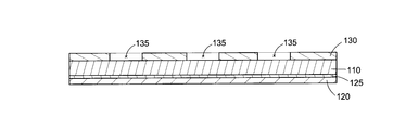
- the upper surface of the aluminum substrate 110 in FIG. 4 is defined as a first surface 110A, and the lower surface of the aluminum substrate 110 is defined as a second surface 110B.
- the second step is a support plate bonding step in which a resin plate 120 as a support plate is bonded to the second surface 110 ⁇ / b> B of the aluminum substrate 110.
- the resin plate 120 is bonded to the second surface 110 ⁇ / b> B of the aluminum substrate 110 by the adhesive layer 125.
- the resin plate 120 is a layer that supports the non-etched portion 116 (see FIG. 2) surrounded by the recess 115 of the display unit 101 when the aluminum substrate 110 is etched so as to penetrate from the first surface 110A to the second surface 110B.
- a PET (polyethylene terephthalate) film is typically used.
- an olefin film or a polyvinyl chloride film may be used. Note that various adhesives are used for the adhesive layer 125 in consideration of the properties of the etching solution used in the etching process.
- the third step is a mask forming step for forming an etching mask layer 130 on the first surface 110 ⁇ / b> A of the aluminum substrate 110.
- the mask layer 130 is formed by printing masking ink on the first surface 110A of the aluminum substrate 110 by screen printing or inkjet printing.
- Mask layer 130 forms a non-mask region 135 so that a region to be etched is exposed in the region of first surface 110 ⁇ / b> A of aluminum substrate 110.
- This mask layer 130 is also referred to as a resist layer.
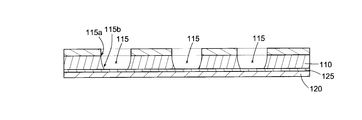
- the fourth process is an etching process that performs an etching process on the aluminum substrate 110 on which the mask layer 130 is formed.
- the aluminum substrate 110 integrated with the resin plate 120 and the mask layer 130 is immersed in an etching solution, whereby the aluminum substrate 110 is etched.
- a recess 115 is formed in aluminum substrate 110 corresponding to non-mask region 135 of mask layer 130 formed on first surface 110 ⁇ / b> A of aluminum substrate 110.
- the aluminum substrate 110 is gradually removed from the first surface 110A of the aluminum substrate 110 toward the second surface 110B to form the recess 115.
- the etching process is performed from the first surface 110 ⁇ / b> A side of the aluminum substrate 110.
- the dimension (width) of the recess 115 on the first surface 110 ⁇ / b> A side of the aluminum substrate 110 is larger than the dimension (width) of the recess 115 on the second surface 110 ⁇ / b> B side of the aluminum substrate 110.
- the opening end 115a on the first surface 110A side of the aluminum substrate 110 has an obtuse angle (an angle greater than 90 degrees), and the opening end 115b on the second surface 110B side of the aluminum substrate 110 has an acute angle (90 Angle smaller than degrees).
- the fifth step is a mask removal step of removing the mask layer 130 from the first surface 110A of the aluminum substrate 110 after the etching process.
- the mask layer 130 is removed with a stripping solution.
- a stripping solution that does not affect the aluminum substrate 110 or the resin plate 120 is used. Note that the mask layer 130 may be removed by photoexcitation ashing or plasma ashing.
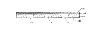
- the sixth step is a resin film bonding step in which the resin film 140 is bonded to the first surface 110 ⁇ / b> A of the aluminum substrate 110.
- Resin film 140 is bonded to first surface 110 ⁇ / b> A of aluminum substrate 110 by adhesive layer 145.
- the adhesive layer 145 is typically a film-like hot melt adhesive or an adhesive formed by printing or coating.
- the resin film 140 is typically a transparent or translucent PC (polycarbonate) film.
- the resin film 140 is bonded to the first surface 110A of the aluminum substrate 110 by applying pressure and heating to the first surface 110A of the aluminum substrate 110 via the adhesive layer 145.
- the seventh step is a support plate removing step for removing the resin plate 120 as the support plate from the second surface 110 ⁇ / b> B of the aluminum substrate 110.
- the second surface 110B of the aluminum substrate 110 is exposed as a design surface.
- the floating island-shaped non-etched portion 116 is held by the resin film 140. That is, the function of holding the non-etched portion 116 is transferred from the resin plate 120 on the second surface 110B of the aluminum substrate 110 to the resin film 140 on the first surface of the aluminum substrate 110.
- the eighth step is a painting / printing step for forming a colored ink layer 148 on the resin film 140.
- the colored ink layer 148 is preferably formed to have translucency so as to transmit light irradiated from the back surface of the design display molded article 100. This makes it possible to control the dimming of the symbol.
- the ninth step is a resin molding step of molding the molding resin 150 on the first surface side of the aluminum substrate 110.
- the molding resin 150 is molded by performing insert molding on the aluminum substrate 110 with the resin film 140 arranged in a predetermined molding die.
- the aluminum substrate 110 and the molding resin 150 can be integrally molded without using an adhesive or the like in the injection molding, and therefore, from the viewpoint of process rationalization and cost reduction. It will be advantageous.
- a switch operation knob for vehicle-mounted product operation is applied as the molding resin 150, it is also useful in that the part can be reliably and easily fixed to the aluminum base material.
- the symbol display molded article 100 is formed by the first to ninth steps.
- display portions 101 corresponding to the plurality of symbol display molded articles 100 may be formed on the aluminum substrate 110.
- it has the cutting process of cut
- the manufacturing efficiency of the molded article 100 for symbol display is improved.
- the aluminum substrate 110 with the resin film 140 may be folded into a predetermined shape and formed. That is, the manufacturing method of the symbol display molded article 100 may have a forming step between the eighth step and the ninth step. This forming is performed by a method such as vacuum forming, pressure forming, or press forming. Note that the forming process may be performed before the cutting process or after the cutting process.
- the resin plate 120 for supporting the non-etched portion 116 may not be provided. That is, the second step (support plate bonding step) can be omitted depending on the shape of the display unit 101. Further, when the second step (support plate bonding step) is omitted, the seventh step (support plate removing step) is also omitted.
- the eighth step can be omitted.
- the color of the transparent or translucent resin film 140 is visually recognized as the color of the display unit 101. Therefore, the resin film 140 may be formed of an opaque colored resin.
- a resin film 140 having a colored layer is prepared, and in the sixth step (resin film bonding step), the resin film 140 having the colored layer is attached to the aluminum substrate 110.
- the eighth step may be omitted.
- the colored layer may be provided on the surface of the resin film 140 on the aluminum substrate 110 side, or may be provided on the surface opposite to the aluminum substrate 110.
- the ninth step (resin molding step) can be omitted.
- the symbol display molded article 100 is constituted by the aluminum substrate 110 and the resin film 140.
- the manufacturing method according to this embodiment includes at least the first step (base material preparation step), the third step (mask formation step), the fourth step (etching treatment step), the fifth step (mask removal step), And the 6th process (resin film adhesion process) should just be provided.
- the order of the second step (support plate bonding step) and the third step (mask forming step) can be interchanged.
- the order of the seventh step (support plate removing step) and the eighth step (painting / printing step) can be interchanged.
- the first surface 110A of the aluminum substrate 110 is set as an etching start surface
- the second surface 110B of the aluminum substrate 110 is set as a design surface for symbol display. ing.
- the resin plate 120 as a support plate, the second surface 110B of the aluminum substrate 110 is used as a design surface, and the first surface 110A of the aluminum substrate 110 is used as an etching start surface. Even in this case, the floating island-shaped non-etched portion 116 in the display portion 101 can be formed.
- the symbol display molded product 100 as a vehicle-mounted panel used in a vehicle speedometer or the like has been described.
- this molded product is visually-recognized information for a vehicle occupant.
- the application is not limited to the in-vehicle panel.
- the present invention may be applied to a push-type engine starter switch formed as a symbol display molded product 100.
- the display unit 101 is provided on the second surface 110B of the aluminum substrate 110 pressed by the user.
- a resin film 140 and a molding resin 150 are provided on the first surface of the aluminum substrate 110.
- the first surface 110A and the second surface 110B of the aluminum substrate 110 are defined. That is, if the design surface and the etching start surface are set to different surfaces, the first surface 110A of the aluminum substrate 110 may be set as the design surface and the second surface 110B may be set as the etching start surface.
- the support plate 120 is bonded to the first surface 110A of the aluminum substrate 110, and the resin film 140 and the molding resin 150 are provided on the second surface 110B of the aluminum substrate 110.
Landscapes
- Engineering & Computer Science (AREA)
- Chemical & Material Sciences (AREA)
- Mechanical Engineering (AREA)
- Combustion & Propulsion (AREA)
- Transportation (AREA)
- General Chemical & Material Sciences (AREA)
- Chemical Kinetics & Catalysis (AREA)
- Materials Engineering (AREA)
- Metallurgy (AREA)
- Organic Chemistry (AREA)
- Manufacturing & Machinery (AREA)
- ing And Chemical Polishing (AREA)
- Instrument Panels (AREA)
- Injection Moulding Of Plastics Or The Like (AREA)
Abstract
La présente invention a pour but de fournir une configuration améliorée pour améliorer la visibilité d'informations de dessin affichées sur un article moulé à bord d'un véhicule. Pour atteindre ce but, l'invention consiste en un article moulé d'affichage de dessin 100 qui possède une plaque de base en aluminium ayant une première surface 110A et une seconde surface 110B se faisant face, la seconde surface 110B ayant un dessin formé sur celle-ci. La plaque de base en aluminium 110 de l'article moulé affichant un dessin présente : un renfoncement 115 formé depuis la première surface 110A jusqu'à la seconde surface 110B de telle sorte qu'un bord d'ouverture 115B sur la seconde surface 110B est en angle aigu ; un motif prédéterminé 101 formé sur la seconde surface 110B par le renfoncement, qui constitue une information visible pour un occupant du véhicule.
Applications Claiming Priority (2)
| Application Number | Priority Date | Filing Date | Title |
|---|---|---|---|
| JP2016025181A JP2017140801A (ja) | 2016-02-12 | 2016-02-12 | 車載用成形品 |
| JP2016-025181 | 2016-02-12 |
Publications (1)
| Publication Number | Publication Date |
|---|---|
| WO2017138657A1 true WO2017138657A1 (fr) | 2017-08-17 |
Family
ID=59563099
Family Applications (1)
| Application Number | Title | Priority Date | Filing Date |
|---|---|---|---|
| PCT/JP2017/005004 Ceased WO2017138657A1 (fr) | 2016-02-12 | 2017-02-10 | Article moulé à bord d'un véhicule |
Country Status (2)
| Country | Link |
|---|---|
| JP (1) | JP2017140801A (fr) |
| WO (1) | WO2017138657A1 (fr) |
Citations (2)
| Publication number | Priority date | Publication date | Assignee | Title |
|---|---|---|---|---|
| JP2000199082A (ja) * | 1998-12-28 | 2000-07-18 | Corona International Kk | アルミニウム薄板の彫り抜き表示成形品の製造法並びに彫り抜き成形品 |
| JP2014113777A (ja) * | 2012-12-11 | 2014-06-26 | Tokai Rika Co Ltd | 金属加飾品製造方法及び金属加飾品 |
-
2016
- 2016-02-12 JP JP2016025181A patent/JP2017140801A/ja active Pending
-
2017
- 2017-02-10 WO PCT/JP2017/005004 patent/WO2017138657A1/fr not_active Ceased
Patent Citations (2)
| Publication number | Priority date | Publication date | Assignee | Title |
|---|---|---|---|---|
| JP2000199082A (ja) * | 1998-12-28 | 2000-07-18 | Corona International Kk | アルミニウム薄板の彫り抜き表示成形品の製造法並びに彫り抜き成形品 |
| JP2014113777A (ja) * | 2012-12-11 | 2014-06-26 | Tokai Rika Co Ltd | 金属加飾品製造方法及び金属加飾品 |
Also Published As
| Publication number | Publication date |
|---|---|
| JP2017140801A (ja) | 2017-08-17 |
Similar Documents
| Publication | Publication Date | Title |
|---|---|---|
| US12198577B2 (en) | Decorative film, decorative film body, display body and methods for production thereof | |
| JP4541016B2 (ja) | 繊細な図記号が装備された操作ボタン、装飾パネルおよびインストルメントパネルの製造方法 | |
| EP2311689A1 (fr) | Méthode de fabrication d'un élément décoratif, en particulier destiné à être utilisé comme emblème sur un véhicule à moteur | |
| US12337769B2 (en) | Control unit for a vehicle interior and method for producing the control unit | |
| CN109416899B (zh) | 具有部分膜和涂漆的过渡部掩盖的显示元件 | |
| US11745649B2 (en) | Vehicle panel including a perforated pattern and a method of manufacturing same | |
| JP4803820B2 (ja) | 背光表示パネル及びその製造方法 | |
| JPH0450687B2 (fr) | ||
| JP2000305495A (ja) | 着色透光表示体及びその製造方法 | |
| WO2017138657A1 (fr) | Article moulé à bord d'un véhicule | |
| JP5138010B2 (ja) | 金属調化粧シートの製造方法、及び当該金属調化粧シートを用いたインサート成形体の製造方法 | |
| JP6608206B2 (ja) | 車載用成形品、および車載用成形品の製造方法 | |
| JP2006500554A (ja) | 表示デバイス | |
| KR101511524B1 (ko) | 로고 라벨 제조 방법 | |
| US20040055193A1 (en) | Backlit sign | |
| JP4768286B2 (ja) | 車両用計器装置及びその製造方法 | |
| JP6211134B1 (ja) | 照光式表示板及び照光式表示板の製造方法 | |
| KR102147177B1 (ko) | 레이저 식각을 이용한 투명기판 베이스 칼라 명판 제작방법 및 그 투명기판 베이스 칼라 명판 | |
| US20250388082A1 (en) | Display device for a vehicle and associated manufacturing method | |
| US12187124B2 (en) | Display device having a cover body forming a plurality of display areas to be backlit and meeting different optical requirements, associated use and associated production method | |
| JP5441592B2 (ja) | 車両用金属調加飾部品及びその製造方法 | |
| JP7187653B1 (ja) | クッション性を備え、加飾された成形樹脂製品およびその製造方法 | |
| CN215851052U (zh) | 一种车膜结构、套装以及车辆 | |
| JP2011016298A (ja) | 装飾体 | |
| JP2000199082A (ja) | アルミニウム薄板の彫り抜き表示成形品の製造法並びに彫り抜き成形品 |
Legal Events
| Date | Code | Title | Description |
|---|---|---|---|
| 121 | Ep: the epo has been informed by wipo that ep was designated in this application |
Ref document number: 17750378 Country of ref document: EP Kind code of ref document: A1 |
|
| NENP | Non-entry into the national phase |
Ref country code: DE |
|
| 122 | Ep: pct application non-entry in european phase |
Ref document number: 17750378 Country of ref document: EP Kind code of ref document: A1 |