WO2017138781A1 - Four - Google Patents
Four Download PDFInfo
- Publication number
- WO2017138781A1 WO2017138781A1 PCT/KR2017/001500 KR2017001500W WO2017138781A1 WO 2017138781 A1 WO2017138781 A1 WO 2017138781A1 KR 2017001500 W KR2017001500 W KR 2017001500W WO 2017138781 A1 WO2017138781 A1 WO 2017138781A1
- Authority
- WO
- WIPO (PCT)
- Prior art keywords
- cooking chamber
- coating film
- oven
- wall
- fan
- Prior art date
- Legal status (The legal status is an assumption and is not a legal conclusion. Google has not performed a legal analysis and makes no representation as to the accuracy of the status listed.)
- Ceased
Links
Images















Classifications
-
- C—CHEMISTRY; METALLURGY
- C09—DYES; PAINTS; POLISHES; NATURAL RESINS; ADHESIVES; COMPOSITIONS NOT OTHERWISE PROVIDED FOR; APPLICATIONS OF MATERIALS NOT OTHERWISE PROVIDED FOR
- C09D—COATING COMPOSITIONS, e.g. PAINTS, VARNISHES OR LACQUERS; FILLING PASTES; CHEMICAL PAINT OR INK REMOVERS; INKS; CORRECTING FLUIDS; WOODSTAINS; PASTES OR SOLIDS FOR COLOURING OR PRINTING; USE OF MATERIALS THEREFOR
- C09D1/00—Coating compositions, e.g. paints, varnishes or lacquers, based on inorganic substances
-
- F—MECHANICAL ENGINEERING; LIGHTING; HEATING; WEAPONS; BLASTING
- F24—HEATING; RANGES; VENTILATING
- F24C—DOMESTIC STOVES OR RANGES ; DETAILS OF DOMESTIC STOVES OR RANGES, OF GENERAL APPLICATION
- F24C15/00—Details
- F24C15/005—Coatings for ovens
-
- C—CHEMISTRY; METALLURGY
- C09—DYES; PAINTS; POLISHES; NATURAL RESINS; ADHESIVES; COMPOSITIONS NOT OTHERWISE PROVIDED FOR; APPLICATIONS OF MATERIALS NOT OTHERWISE PROVIDED FOR
- C09D—COATING COMPOSITIONS, e.g. PAINTS, VARNISHES OR LACQUERS; FILLING PASTES; CHEMICAL PAINT OR INK REMOVERS; INKS; CORRECTING FLUIDS; WOODSTAINS; PASTES OR SOLIDS FOR COLOURING OR PRINTING; USE OF MATERIALS THEREFOR
- C09D5/00—Coating compositions, e.g. paints, varnishes or lacquers, characterised by their physical nature or the effects produced; Filling pastes
- C09D5/16—Antifouling paints; Underwater paints
-
- F—MECHANICAL ENGINEERING; LIGHTING; HEATING; WEAPONS; BLASTING
- F24—HEATING; RANGES; VENTILATING
- F24C—DOMESTIC STOVES OR RANGES ; DETAILS OF DOMESTIC STOVES OR RANGES, OF GENERAL APPLICATION
- F24C14/00—Stoves or ranges having self-cleaning provisions, e.g. continuous catalytic cleaning or electrostatic cleaning
-
- F—MECHANICAL ENGINEERING; LIGHTING; HEATING; WEAPONS; BLASTING
- F24—HEATING; RANGES; VENTILATING
- F24C—DOMESTIC STOVES OR RANGES ; DETAILS OF DOMESTIC STOVES OR RANGES, OF GENERAL APPLICATION
- F24C15/00—Details
Definitions
- the present invention relates to an oven, and more particularly, to an oven having an improved structure to keep the cooking chamber clean.
- Pyro Cleaning is a method of cleaning the inside of an oven at a high temperature of 420 ° C. or higher, which takes 2 to 4 hours, but is used by consumers in Europe and America in particular.
- Teflon registered trademark
- Teflon is weak to high heat and generates harmful gases at high temperatures, and thus cannot be used in a temperature environment of 250 ° C. or higher, such as an oven inner wall.
- a material having another liquid repellent component when exposed to a temperature environment of up to 420 ° C. such as pyro cleaning, the liquid repellency is lost, and the antifouling effect cannot be expected after the next time. Therefore, when the coating film which has liquid repellent performance is applied to the inner wall of an oven, it is conventionally comprised so that a pyro cleaning function may not be mounted (refer patent document 1).
- the required liquid-repellent surface is capable of maintaining a predetermined liquid-repelling performance for a long time without cracking in the film due to repetition of heat load at 350 ° C.
- the method of depositing the coating film which has the above-mentioned characteristic on the oven inner wall is not specifically known.
- oil droplets from meat and the like are discolored and thicken when heated by cooking, and eventually become black, hard, small pieces that cling to the inner wall of the oven. That is, even in the inner wall of the oven having the coating film, the problem that small spots of contaminants remain.
- Patent Document 2 is configured to vibrate the inner wall of the oven to drop the deposit, but this targets a relatively large volume, so that even if there is a coating film, it is possible to remove a small volume of oil droplets or water drops that are still attached. It is not composed.
- Patent Document 1 United States Patent Application Publication No. 2013-192582
- Patent Document 2 Japanese Patent Laid-Open No. 2005-230162
- One aspect of the present invention provides an oven having a coating film having a liquid repellent performance that can prevent contaminants such as oil, and having durability against repeated heat load.
- Another aspect of the present invention provides a method for forming a coating film for an oven having a liquid repellent performance that can prevent contaminants such as oil, and having a durability against repeated heat load.
- Still another aspect of the present invention provides an oven capable of preventing a contaminant from adhering to the inner wall of the oven even if a small volume of oil or water drops from the inner wall of the oven.
- Another aspect of the present invention provides an oven capable of dropping contaminants adhered to the inner wall of the oven by a simple method without impairing the liquid repellency of the coating film formed on the inner wall of the oven.
- Another aspect of the present invention is to further reduce the contaminants of the coating film is formed over a long period of time, which can reduce the contaminants caused by the deposition of very fine oil droplets attached to the coating film, and in a simple operation Provide an oven that can drop contaminants.
- an oven includes a cooking chamber inner wall forming a cooking chamber in which a cooking object is accommodated, and a coating film having a predetermined film thickness formed on the cooking chamber inner wall, wherein the coating film has liquid repellency.
- contaminants such as oil generated from the cooked material can be prevented from adhering to the inner wall of the cooking chamber. Therefore, the user can simply remove the contaminants stuck to the inner wall of the cooking chamber without rubbing the brush or the like, thereby reducing the effort required for cleaning.
- contaminants tend to fall off by the coating film, contaminants can be sufficiently dropped without performing pyrocleaning up to 420 ° C as in the prior art. Therefore, since it is not necessary to repeat the pyro cleaning, it is possible to reduce the load of the heater mechanism or the like and reduce the frequency of failure of the oven.
- the coating film may have a surface characteristic of a contact angle of 100 ° or more.
- the inventors of this application etc. as a result of earnestly examining, when the film thickness of the said coating film is 0.2 micrometer or more and 3 micrometers or less, even if cooking of a to-be-cooked thing is repeated and the heat load which reaches 350 degreeC, for example in a coating film is repeated, the liquid repellency performance is almost impaired. It was also found that cracking was unlikely to occur in the coating film.
- the oven according to the idea of the present invention can be made to have a durability against the heat load while making it easy to drop the contaminants using the coating film.
- the film thickness of the coating film is preferably 0.2 ⁇ m or more and 2 ⁇ m or less.
- the film thickness of the coating film is 0.5 ⁇ m or more and 1.5 ⁇ m or less.
- the said coating film should just have a surface characteristic that the contact angle at the time of oil contacting the surface becomes 40 degrees or more.
- the coating film is combined at a ratio of 5% or more and 28% or less with respect to the total weight of the solid component of the material containing the solvent. All you need is
- the coating film may be formed in one layer.
- the said coating film should just be formed in two layers.
- the coating film is applied to the surface of the inner wall of the cooking chamber in order to release cracks and the like while releasing internal stress generated during curing. After heating to a 1st temperature in a state, what was necessary is just to heat and harden
- the coating film may be one obtained by applying and curing the second layer of the coating film on the first layer before the first layer of the coating film is completely cured. If it is such a thing, before a 1st layer exhibits liquid repellency, a 2nd layer can be apply
- the said interior wall of the said cooking chamber is what the enamel was coated on the steel plate, and the thing in which the said coating film was apply
- the said cooking chamber inner wall is formed with the steel plate, and the coating film was apply
- the inner surface of the viewing window provided on the door for inserting and removing the workpiece into the cooking chamber in order to make it difficult to stick the contaminants caused by oil or the like even on the viewing window, for example, to check the state of the workpiece inside the oven. What is necessary is just to apply.
- the coating film forming method according to the spirit of the present invention is a method of forming a coating film on the inner wall of the cooking chamber that forms the cooking chamber in which the workpiece is to be accommodated, and a silicone- or alkyl-based liquid-repellent material is added to a material having a silsesquioxane as a skeleton.
- a solution in which one coating material is dissolved in a solvent is applied to the inner wall of the cooking chamber by spray coating.
- the coating film can maintain reliability for a long time without losing its liquid repellency.
- the coating material may be combined in an amount of 5% or more and 20% or less with respect to the total weight of the solution.
- the coating film can be formed at the film thickness described above, the durability against heat load can be greatly improved.
- the spray target is sprayed while moving the spray target, and the spray target is sprayed twice against the inner wall of the cooking chamber.
- the solution may be applied three times.
- the solvent capable of satisfactorily forming the coating film include any one of hexane, heptane, octane, butyl acetate, PEGMEA, and ethyl acetate.
- an oven includes a coating film having liquid repellency formed on an inner wall of a cooking chamber that forms a cooking chamber in which a workpiece is accommodated, a vibrator for vibrating the inner wall of the cooking chamber in at least a vertical direction, and the vibrator with a predetermined amplitude.
- a control unit for controlling to oscillate at a reverse frequency and a predetermined frequency range, wherein the predetermined frequency range is set to include a resonance frequency of the droplet determined according to the size of the droplet attached to the inner wall of the cooking chamber. do.
- the inner wall of the cooking chamber vibrates in the vertical direction at the resonance frequency of the droplet, even if the coating film is present, even if a small droplet is not dropped from the inner wall of the cooking chamber by its own weight, the droplet can be moved in the vertical direction and dropped. Done.
- the said predetermined frequency range may be 20 Hz or more and 220 Hz or less in order to effectively resonate and drop the small droplet which does not fall by self weight from the inner wall of the cooking chamber even if there is the coating film.
- the predetermined amplitude range may be set to 10 ⁇ m or more and 100 ⁇ m or less in order to effectively remove the droplets adhering to the inner wall of the cooking chamber while reducing the sound generated by the vibrator.
- the control unit further includes a heater mechanism for heating the inside of the cooking chamber in order to increase the viscosity of the droplet having a small volume so that vibration through the inner wall of the cooking chamber can be easily transmitted.
- the oscillator may be further controlled to vibrate the inner wall of the cooking chamber in a state in which the heater mechanism is controlled to maintain the cooking chamber or the inner wall of the cooking chamber at 60 ° C to 350 ° C.
- control unit is configured to continuously vibrate the inner wall of the cooking chamber within 10 seconds to 60 seconds in order to generate resonance with the droplets and to move from the inner wall of the cooking chamber to the bottom surface of the cooking chamber, for example. do.
- the control unit changes the frequency of vibration of the vibrator at 10 Hz or less per second to be within the predetermined frequency range. It may be configured to sweep the.
- control unit controls the cooked material in the cooking chamber to prevent contamination. What is necessary is just to be comprised so that the cooking mode heated by a heater mechanism and the cleaning mode which vibrates the inner wall of the said cooking chamber by the said vibrator after completion
- finish of the said cooking mode may be performed.
- An oven includes a coating film having a liquid repellency formed on an inner wall of a cooking chamber that forms a cooking chamber in which a cooking object is accommodated, a heater mechanism for heating the inside of the cooking chamber, and a fan that generates air flow in the cooking chamber. And a control unit for controlling the heater mechanism and the fan, wherein the control unit has a state in which the temperature of the inner wall of the cooking chamber is 350 ° C. or higher and 400 ° C. or lower in a cleaning mode for dropping contaminants attached to the inner wall of the cooking chamber.
- the fan is characterized in that it is configured to drive the fan at the same time while driving the heater mechanism to continue for a predetermined holding time or more.
- the contaminants may be dropped by heat.
- the temperature of the inner wall of the cooking chamber is maintained at 350 ° C. or higher and 400 ° C. or lower, the temperature may be lower than that of conventional pyro cleaning, and the loss of liquid repellency of the coating film due to high temperature can be prevented.
- the user since the user does not need to rub the inner wall of the cooking chamber with a brush or the like, the time and effort required for cleaning can be reduced.
- the predetermined holding time may be set to 1 hour or more in order to sufficiently drop even when heavy contaminants adhere to the inner wall of the cooking chamber.
- the controller controls the temperature distribution on the standing surface of the inner wall of the cooking chamber.
- the heater mechanism and the fan may be controlled so that the deviation is within 15 ° C.
- the heater mechanism includes an upper heater for heating the upper part of the cooking chamber, a lower heater for heating the lower part of the cooking chamber, and
- the rear surface heater which heats a back part may be provided, and the said fan should just be provided in the back side in the said cooking chamber.
- the control unit is within the predetermined holding time.
- the fan is operated so that the operation rate of the fan is 50% or more, and the operation rate of the rear heater within the predetermined holding time is 30% or more and 80% or less, and the operation rates of the upper heater and the lower heater are 40% or less.
- the thing comprised so that it may become may be mentioned.
- the control unit alternately drives the upper heater and the lower heater in order to be able to maintain the temperature of the inner wall of the cooking chamber uniformly at the high temperature described above while continuing to reduce the amount of power required at one time in the heater mechanism. It may be configured to.
- control unit may be driven such that the ON time of each of the upper heater and the lower heater is 10 seconds or more and 40 seconds or less.
- the air flow formed by the fan is 1 m / s or more at a position 1 cm away from the standing surface of the inner wall of the cooking chamber.
- An oven according to the spirit of the present invention is provided in a cooking chamber inner wall which forms a cooking chamber in which a workpiece is to be housed, a main heater disposed in the cooking chamber, and a place different from the main heater in the cooking chamber. And a coating film having a liquid repellency of a predetermined film thickness formed on the inner wall of the cooking chamber, and a portion of the inner wall of the oven where the circulation of the hot air formed by the fan collides with the coating film.
- the contaminant collecting portion is formed by a surface having a low liquid repellency.
- the oil droplets bounced off the coating film formed on the inner wall of the cooking chamber or the minute oil droplets contained in the circulating wind are collected by the contaminant collecting portion, so that the minute oil droplets are deposited on the coating film, and black as small contaminants. Discoloration can be prevented. Therefore, it is easy to maintain the cleanliness of the portion where the coating film is formed over a long period of time.
- the contaminant collecting portion In order to easily clean the contaminant collecting portion in which the oil droplets causing contaminants in the cooking chamber of the oven are concentrated, and to maintain the collecting effect of the oil droplets and to maintain the cleanliness of other parts, the contaminant collecting portion may be What is necessary is just to form in the detachable member in the said cooking chamber.
- the contaminant collecting part may be formed on the inner wall surface of the door for inserting and removing the workpiece into the cooking chamber.
- the contaminant collecting unit may be formed in a viewing window of a door for inserting and removing a workpiece into the cooking chamber. Since the sight glass of the door is the front side of the oven, it is easy for the user to clean it.
- the surface energy of the coating film may be 20 mJ / m 2 or less.
- the surface energy of the contaminant collecting unit may be 25 mJ / m 2 or more in order to make it possible to collect the small droplets of oil in the contaminant collecting unit sufficiently so that small dots of contaminants are hardly generated in the coating film.
- the difference between the surface energy of the coating film and the surface energy of the contaminant concentrator may be at least 5 mJ / m 2 .
- the contaminant collecting portion may be disposed in the pan, allowing the contaminant collecting portion to be collected before the minute oil droplets reach the coating film, thereby maintaining the cleanliness in the cooking chamber as a whole and being simple.
- the contaminant collecting unit may be formed of a metal plate, and may be detachably attached to the inner wall of the cooking chamber.
- the metal plate may be formed of any one of SUS430, a plated steel sheet, and an enameled steel sheet.
- the metal plate stands in the cooking chamber, and the collected liquid contaminants are lowered by their own weight. What is necessary is just to be comprised so that it may be gathered in the waste liquid container which was detachably installed in the said cooking chamber.
- the contaminant collecting unit has a catalyst coating layer, and the catalyst coating layer is formed of Ag.
- a compound containing at least one of Pt, Pd, Au, Cu, Ru, Ti, and Ni as a catalyst and include MnO 2, CeO 2, Al 2 O 3, Bi 2 O 3, SnO, TiO 2, Cr 2 O 3, Co 2 O 3, Fe 2 O 3, CuO, ZrO 2, What is necessary is just to include the compound containing at least one of SrO, LaO, V2O5, Li2O, ZnO, MgO, NiO, CuO, and BaO as a promoter or a supporting material.
- an undercoat layer is formed between the catalyst coating layer and a metal plate as a base material, and the undercoat layer is Low molecular weight Silane coating material containing Silane, Vinyl-Siloxane, Ethoxy-Alumina phosphate and Alkyl-Aryl Siloxane, or Polysilazane-based coating solution mainly composed of PerHydro-Polysilazane (PHPS) or Organo-Polysilazane (OPSZ) a predetermined thickness of -order is as long as it has SiO 2 film.
- PHPS PerHydro-Polysilazane
- OPSZ Organo-Polysilazane
- a heater mechanism including the main heater and a control unit for controlling the fan are further provided, and the control unit is configured to decompose contaminants deposited on the catalyst coating layer.
- the temperature range is 250 ° C or more and 400 ° C or less.
- the heater mechanism further includes a catalyst coating layer heating heater for heating the catalyst coating layer, It is configured to heat the catalyst coating layer to the temperature range by ON / OFF control of the catalyst coating layer heating heater and the fan.
- the controller may control the ON duty of the pan to be 16% or more and 20% or less.
- the distance between the said catalyst coating layer and the said catalyst coating layer heating heater is set to 1 mm or less.
- the catalyst coating layer is sufficiently exerted during the cooking. What is necessary is just to be comprised so that operation
- movement of a heater may be performed at the time of normal cooking.
- the contaminant collecting portion is convex with respect to the outer circumferential direction of the fan by air flow formed by the fan, and is a vane standing up against the inner wall of the cooking chamber provided around the fan, and the air flow discharged from the fan is What is necessary is just to be comprised so that the vane may be deflected and gradually deflected from the centrifugal direction to the tangential direction.
- the vanes may be arranged in a plurality of radial forms around the pan.
- the said vane is formed along the spiral curve centering on the said fan.
- the said vanes differ in the length of a flow direction, it can be set as the arrangement suitable for collecting a micro oil droplet according to the airflow formed by the said fan.
- the back plate which forms the inner wall of the cooking chamber in which the vanes are installed has a flow of circulation wind. What is necessary is just to form the vortex generator which has a convex shape in the direction.
- the pollutant collection part what is a filter formed from the porous material or the fiber material provided in the flow path of the hot wind circulation by the said fan is mentioned.
- An oven includes a main body, a cooking chamber provided inside the main body, a main heater disposed inside the cooking chamber, a fan disposed inside the cooking chamber to circulate air heated by the main heater, and the cooking chamber. It may include a coating film formed on at least a portion of the inner wall, having a liquid repellency and a liquid repellency smaller than that of the coating film and provided on the inner wall of the cooking chamber in which air circulated by the fan collides.
- the surface energy of the coating film is 20mJ / m 2 or less, the surface energy of the contaminant collecting portion may be 25mJ / m 2 or more.
- the contaminant collecting part may include a body detachably installed on the inner wall of the cooking chamber and a waste solution receiver provided to collect contaminants separated from the body by its own weight.
- the contaminant collecting part may include a plurality of vanes installed along the outer circumferential direction of the fan so as to gradually deflect the air flow discharged from the fan from the centrifugal direction of the fan in the tangential direction of the fan.
- a plurality of protrusions may be formed between the plurality of vanes.
- the contaminant collecting part may include a filter disposed at at least one of a suction port and a discharge port of the fan, and the filter may be formed of at least one of a porous material and a fiber material.
- the contaminant collecting part may be detachably provided on an inner wall of the cooking chamber.
- the contaminant collecting portion may be separable by magnetic.
- the contaminant collecting unit may include a catalyst coating layer, the catalyst coating layer is Ag, Pt, Pd, Au, Cu, Ru, Ti, and catalysts, and containing at least one of Ni MnO 2, CeO 2, Al 2 O 3, Bi 2 O 3 , SnO, TiO 2 , Cr 2 O 3 , Co 2 O 3 , Fe 2 O 3 , CuO, ZrO 2 , SrO, LaO, V 2 O 5 , Li 2 O, ZnO, MgO, NiO, CuO and BaO It may include a promoter including at least one of.
- the oven according to the spirit of the present invention may further include a catalyst coating layer heating heater installed in the cooking chamber to heat the catalyst coating layer, and the distance between the catalyst coating layer and the catalyst coating layer heating heater may be 1 mm or less.
- the coating layer may include a base material including silsesquioxane and a coating material including at least one of a silicon-based liquid repellent and an alkyl-based liquid repellent.
- the coating film may have a water contact angle of 100 ° or more and a thickness of 0.2 ⁇ m or more and 3 ⁇ m or less.
- the coating film may have an oil contact angle of 40 ° or more and a thickness of 0.2 ⁇ m or more and 3 ⁇ m or less.
- the coating film may include at least one layer.
- the at least one layer may include a first layer applied to at least a portion of the inner wall of the cooking chamber and a second layer applied on the first layer before the first layer is cured.
- An oven according to the spirit of the present invention includes a main body, a cooking chamber provided inside the main body, and a coating film formed on at least a portion of the inner wall of the cooking chamber, and having a liquid repellency and heat resistance, wherein the coating film includes silsesquioxane. It may include a coating material comprising at least one of the base and the silicone-based liquid repellent and the alkyl-based liquid repellent.
- the coating film may have a water contact angle of 100 ° or more and a thickness of 0.2 ⁇ m or more and 3 ⁇ m or less.
- the coating film may have an oil contact angle of 40 ° or more and a thickness of 0.2 ⁇ m or more and 3 ⁇ m or less.
- Oven according to the spirit of the present invention may further include a contaminant collecting unit having a liquid repellency smaller than the coating film.
- the oven according to the spirit of the present invention may further include a door rotatably installed in the main body to open and close the cooking chamber, and the contaminant collecting unit may be provided on an inner surface of the door facing the cooking chamber.
- the coating film having a film thickness of 0.2 ⁇ m or more and 3 ⁇ m or less is formed on the inner wall of the cooking chamber, contaminants caused by oil or the like are hard to stick to the inner wall of the cooking chamber according to the liquid repellency of the coating film. For example, it is possible to prevent cracks from occurring even when the heat load of about 350 ° C. is repeated by repeating cooking. Therefore, the antifouling effect can be maintained for a long time, and the time required for cleaning in the oven can be reduced.
- there is a coating film contaminants in the oven can be easily dropped, so that a very high temperature cleaning method such as conventional pyro cleaning is not required. Thereby, the load on the said oven can be reduced and the frequency
- the film thickness can be thickened to, for example, 0.2 ⁇ m or more and 3 ⁇ m or less with respect to a coating film having a surface characteristic with a contact angle of water of 100 ° or more. Therefore, it becomes possible to give the cooking chamber inner wall the outstanding antifouling effect and durability to a heat load.
- the inner wall of the cooking chamber is configured to vibrate at a frequency range including a resonance frequency of the droplet determined according to the size of the droplet attached to the inner wall of the cooking chamber, the minute liquid attached to the coating film. Even if it is an enemy, it can be eliminated by resonance, and it can prevent that it becomes a clinging pollutant.
- the oven according to the present invention even if contaminants derived from oil or the like adhere to the inner wall of the cooking chamber in which the coating film is formed, it can be dropped by high temperature. More specifically, it has been thought that if contaminants derived from oil or the like cannot be dropped unless the temperature of the cooking chamber and the inner wall of the cooking chamber is maintained at a very high temperature of 420 ° C. like pyro cleaning. On the other hand, as a result of intensive investigation by the inventors of the present invention, when the liquid-repellent coating film is formed on the inner wall of the cooking chamber, it has been found that the contaminants can be sufficiently dropped at a lower temperature than previously assumed. Since the cooking chamber inner wall is maintained at 350 ° C. or more and 400 ° C. or less, contaminants may be dropped while the liquid repellency of the coating film may not be lost. Therefore, even if the cleaning mode is implemented, the contaminants are hard to stick to the inner wall of the cooking chamber for a long time.
- the cooking chamber since the cooking chamber has not only an inner wall of the cooking chamber having a liquid-repellent coating film in which oil droplets bounce off, but also a contaminant collecting portion for collecting oil droplets, it is also deposited on the coating film, and contaminants in the form of small spots.
- the minute oil droplets, which are a cause of, can be collected by the contaminant collecting unit, thereby preventing the volume to the coating film. Therefore, it becomes possible to maintain the cleanliness of the part in which the said coating film is formed over a longer term.
- FIG. 1 is a schematic diagram showing the structure of an oven according to a first embodiment of the present invention.
- FIG. 2 is a schematic cross-sectional view showing the structure of the coating film in the first embodiment.
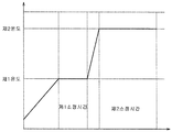
- 3 is a schematic graph showing a temperature profile when curing the coating film in the first embodiment.
- FIG. 5 is a graph showing the durability of the contact angle of water and the heating time according to the film thickness of the coating film in the first embodiment.
- FIG. 6 is a schematic cross section which shows the coating film in the 1st modified example of 1st Example.
- FIG. 7 is a schematic graph showing a temperature profile when curing the coating film in the fourth modification of the first embodiment.
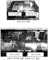
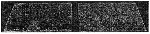
- Fig. 8 is a comparison result showing the antifouling effect when a coating film was formed on the see-through window in the fifth modification of the first embodiment.
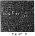
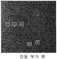
- 10A and 10B are experimental photographs showing movement of water drops by vibrating the inner wall of the cooking chamber in the second embodiment.
- 11A and 11B are experimental photographs showing movement of oil droplets by vibrating the inner wall of the cooking chamber in the second embodiment.
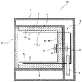
- FIG. 12 is a schematic diagram showing the structure of an oven according to a third embodiment of the present invention.
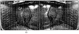
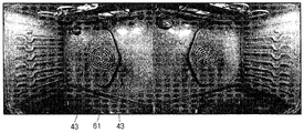
- Fig. 15 is a thermography showing the temperature distribution of the inner wall of the cooking chamber in the third embodiment.
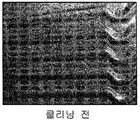
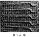
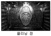
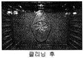
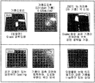
- 16A and 16B are comparison results showing the effect of cleaning in the third embodiment.
- 18A and 18B are comparison results showing the effect of cleaning in the modification of the third embodiment.
- 19 is an experimental result showing the relationship between the air flow and the cleaning effect in the third embodiment.
- 20 is a schematic diagram showing the structure of an oven according to the fourth embodiment.
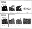
- Fig. 21 is an experimental result showing the improvement of the antifouling effect on the coating film by providing the contaminant collecting part in the fourth embodiment.
- 23 is an experimental result showing the antifouling effect when the coating film is formed on the entire surface in the oven.
- Fig. 25 is a schematic diagram showing the structure of the contaminant collecting unit in the first modification of the fourth embodiment.
- 27 is an experimental result showing the antifouling effect in the first modification of the fourth embodiment.
- Fig. 28 is an experimental result showing the difference of the antifouling effect with or without the contaminant collecting part in the first modification of the fourth embodiment.
- FIG. 29 is an experimental result showing a difference in the amount of soft discharge to the outside depending on the presence or absence of a contaminant collecting unit in the first modification of the fourth embodiment.
- Fig. 30 is a diagram showing a contaminant collecting part in the second modification of the fourth embodiment.
- FIG. 31 is a schematic diagram showing a cleaning result in the second modification of the fourth embodiment.
- Fig. 32 is a diagram showing a contaminant collecting part in the third modification of the fourth embodiment.
- Fig. 33 is an experimental result showing the antifouling effect by the pollutant collecting unit in the fourth modification of the fourth embodiment.
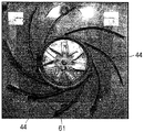
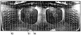
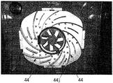
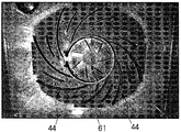
- Fig. 34 is a view showing vanes that are contaminant collecting portions in the fifth modification of the fourth embodiment.
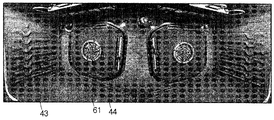
- Fig. 36 is an experimental result showing the antifouling effect by vanes in the fifth modification of the fourth embodiment.
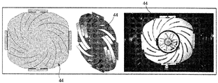
- Fig. 37 is a diagram showing vanes of another example in the fifth modification of the fourth embodiment.
- Fig. 39 is a diagram showing a vane of still another example in the fifth modification of the fourth embodiment.
- FIG. 40 is a diagram showing details of a vortex generator in still another example in a fifth modification of the fourth embodiment.
- Fig. 41 is an experimental result showing the antifouling effect by the vane of still another example in the fifth modification of the fourth embodiment.
- Fig. 42 is an experimental result showing the difference of the contaminant collection effect with or without the vortex generator in the fifth modification of the fourth embodiment.
- FIG. 43 shows an example in which a catalyst coating layer is formed on a vane in the fifth modification of the fourth embodiment.
- Fig. 44 is an experimental result showing the antifouling effect in the middle in the case where the catalyst coating layer is formed on the vane in the fifth modification of the fourth embodiment.
- FIG. 45 is an experimental result showing the final antifouling effect when the catalyst coating layer was formed on the vane in the fifth modification of the fourth embodiment.
- Fig. 46 is a diagram showing an example of the experimental configuration for obtaining the relationship between the decomposition effect of contaminants by the catalyst coating layer and the temperature.
- Fig. 48 is an experimental result showing the decomposition effect of contaminants by the catalyst coating layer at 380 ° C.
- Fig. 49 is an experimental result showing the decomposition effect of contaminants by the catalyst coating layer at 350 ° C.
- 50 is a diagram showing the sixth modification of the fourth embodiment of the present invention.
- Fig. 51 is a view showing the seventh modification of the fourth embodiment of the present invention.
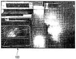
- the oven 100 is configured such that a workpiece is accommodated in the cooking chamber 1 and the workpiece is heated by the heater mechanism 5.
- the oven 100 may include a main body 2 forming an appearance.
- the main body 2 may have a substantially rectangular parallelepiped shape in which the front face is opened.
- the oven 100 may further include a cooking chamber 1 provided inside the main body 2.
- the cooking chamber 1 may have a substantially rectangular parallelepiped shape in which a front surface is opened.
- the cooking chamber 1 may be defined by the cooking chamber inner wall 4.
- the cooking chamber inner wall 4 may include an upper surface 4a, a lower surface 4b, a right side, a left side, and a rear side 4c.
- the oven 100 may further include a door 3 rotatably installed in the main body 2 to open and close the cooking chamber 1.
- the door 3 may be provided with a viewing window so that the state inside the cooking chamber 1 can be checked from the outside.
- the oven 100 may further include a heater mechanism 5 installed in the cooking chamber 1 or in the vicinity of the cooking chamber 1.
- the oven 100 may further include a fan 61 installed to convection or circulate the air heated by the heater mechanism 5.
- the oven 100 may further include a vibrator 7 which vibrates the cooking chamber inner wall 4 to separate contaminants attached to the cooking chamber inner wall 4 from the cooking chamber inner wall 4.
- the oven 100 may further include a heater mechanism 5, a motor 62 driving the fan 61, and a control board 8 that is responsible for controlling the vibrator 7.
- the heater mechanism 5 includes an upper heater 51 installed at the upper part of the cooking chamber 1, a lower heater 52 provided at the lower part of the cooking chamber 1, and a fan 61 at the rear side in the cooking chamber 1. It may include a rear heater 53 installed.
- the upper heater 51 and the rear heater 53 may be installed to be exposed inside the cooking chamber 1, and the lower heater 52 may be installed to be located between the cooking chamber 1 and the main body 2. That is, the lower heater 52 may be installed to be located outside the inner wall 4 of the cooking chamber and inside the main body 2.
- the oven 100 may further include a heat insulator 9 disposed between the cooking chamber 1 and the main body 2. That is, the heat insulating material 9 may be disposed between the outer surface of the cooking chamber inner wall 4 and the inner surface of the main body 2. In addition, the heat insulator 9 may be arranged inside the door 3.
- the oven 100 may further include a coating film 43 formed on at least a portion of the inner wall 4 of the cooking chamber. Detailed description of the coating film 43 will be described later.
- the heater mechanism 5, the fan 61, and the control board 8 can cooperate with each other to control the temperature inside the cooking chamber 1 or its temperature distribution.
- the cooking mode in which the temperature of the cooking chamber inner wall 4 reaches about 350 ° C. is maintained at a temperature higher than the cooking mode for a predetermined time, and the convection of air in the cooking chamber 1 is controlled.
- a cleaning mode for removing contaminants adhering to the inner wall 4 of the cooking chamber is configured.
- the inner wall 4 of the cooking chamber consists of an enamel steel sheet 41 serving as a base material from the outside, and an enamel 42 formed on the enamel steel sheet 41.
- the coating film 43 may be formed on the enamel 42 to be exposed to the inside of the cooking chamber 1. That is, the coating film 43 may be formed on the enamel 42 so as to face the inside of the cooking chamber 1.
- the coating film 43 may have liquid repellency. In other words, at least the outer surface of the coating film 43 may have liquid repellency.
- the outer surface of the coating film 43 refers to a surface facing the inside of the cooking chamber 1.
- the coating layer 43 may have a water contact angle of 100 ° or more.
- the coating film 43 may have an oil contact angle of 40 ° or more when vegetable oil such as rapeseed oil, canola oil, or safflower oil is 60 ° C.
- the coating layer 43 may include a base including silsesquioxane and a coating material including at least one of a silicon-based liquid repellent and an alkyl-based liquid repellent.
- the coating film 43 is obtained by adding a silicon- or alkyl-based liquid repellent material to a material having silsesquioxane as a skeleton.
- “addition” is a concept containing the thing which mixed the liquid repellent material of silicone type or alkyl type with the material which uses silsesquioxane, or couple
- guide_body which substituted a part of material used as the said skeleton with the said liquid repellent material may be used as a coating film. More specifically, even when the surface temperature reaches 350 ° C., the coating film 43 hardly generates thermal denaturation and continues to exhibit predetermined liquid repellency. That is, the coating film 43 may have heat resistance along with liquid repellency.
- the coating film 43 may be formed to have a predetermined film thickness by spray coating after the enamel steel plate 41 and the enamel 42 are formed in a substantially rectangular parallelepiped shape like the cooking chamber inner wall 4. Moreover, you may form the coating film 43 by spin coating in the flat plate state before forming the cooking chamber inner wall 4, and form it in a rectangular parallelepiped shape after that.
- the coating film 43 may apply a liquid coating material on the enamel 42 and then heat to express the liquid repellency and to harden it.
- the coating film 43 is heated to the first temperature for a first predetermined time in a state where it is applied to the surface of the inner wall of the cooking chamber 4. It is heated and cured for a second predetermined time to a second temperature which is higher than one temperature.
- the film thickness of the coating film 43 is set so that even if a cooking mode is repeated, the above-mentioned surface characteristic is substantially continued, and a crack etc. do not generate
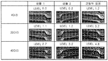
- FIG. 4 shows a state of the inner wall of the cooking chamber 4 for each number of digits in the case where the whole chicken is roasted as a cooking object in the oven 100.
- the level of pollution degree is taken as the average value of sensory evaluation by several people.
- the graph of FIG. 5 shows the change of the water contact angle with respect to the cumulative heating time by giving heat load to the coating film 43 formed with the film thickness of 0.5 micrometer, 0.7 micrometer, 1.0 micrometer, 1.5 micrometer, and 2.0 micrometer.
- the magnitude of the water contact angle correlates positively with the difficulty of attachment of contaminants.
- produced at that time and it is judged that it cannot use further, and the measurement was stopped.
- the film thickness of the coating film 43 is 0.5 ⁇ m or more and 2 ⁇ m or less, good antifouling performance is obtained such that the contact angle of water becomes 100 ° or more until the heating time reaches a cumulative time of about 50 hours. . If it is the range of such a film thickness, it is also preferable also about liquid repellency and durability to a heat load. In addition, when the film thickness of the coating film 43 is 0.7 ⁇ m or more and 1.5 ⁇ m or less, the time for maintaining the water contact angle from 105 ° to 110 ° can be further increased, and the durability against heat load is 200 hours or more in the cumulative heating time. It is more preferable because it can increase.
- the coating film 43 is uniformly formed with a predetermined film thickness, it can be seen that the durability against heat load is improved even if the thickness is 0.7 ⁇ m or less, or even 0.2 ⁇ m or less.
- the coating film 43 may have a film thickness larger than 0 ⁇ m.
- the coating film 43 formed on the inner wall 4 of the cooking chamber is formed in two layers instead of one.
- the two layers refer to a state before or completely after the coating film 43 is completely cured.
- the coating film 43 is before the first layer of the coating film 43 is completely cured on the enamel 42, and the liquid repellency is expressed in the first layer.
- the second layer of the coating film 43 is coated on the first layer and cured.
- the coating layer 43 may include at least one layer.
- the at least one layer may include a first layer applied to at least a portion of the inner wall of the cooking chamber 1 and a second layer applied on the first layer before the first layer is cured.
- the oven 100 of the second modification of the first embodiment is common to the first modification in that the coating film 43 is formed in two layers, but the first layer is a resin layer having no liquid repellency, and the second It differs in that only the layer contains solid content which expresses liquid repellency.
- Table 1 shows the results of comparing the surface conditions when the coating film 43 having such a configuration is cured.
- the coating film 43 formed on the inner wall 4 of the cooking chamber is cured by three temperature changes as shown in the graph of the temperature profile of FIG. 7. That is, the temperature is raised in the order of the first predetermined temperature, the second predetermined temperature, and the third predetermined temperature, and the temperature is kept constant for the first predetermined time, the second predetermined time, and the third predetermined time for each temperature. It is supposed to be.
- the first predetermined time and the second predetermined time are set to be shorter than the third predetermined time, and the lengths thereof are about the same.
- the difference between the first predetermined temperature and the second predetermined temperature is set smaller than the difference between the second predetermined temperature and the third predetermined temperature.
- the temperature profile is not limited to that shown in Figs. 3 and 7, and for example, the temperature change may be smoothly realized so that a temperature difference of a plurality of stages is formed.
- a transparent coating film 43 can also be formed on the inner surface side of the see-through window of the door 3. That is, the coating film 43 may be further formed on the inner surface of the see-through window of the door 3 facing the cooking chamber 1. At this time, the coating film 43 may be transparent.
- FIG. 8 shows a comparison result of contaminants attached to the coating film 43 only on the right side of the see-through window and attached when cooking of the cooked material in the cooking chamber 1.
- FIG. 8 by forming the coating film 43 on the inner surface of the see-through window, it can be seen that the see-through window is clouded and contaminated by oil or the like generated from the workpiece.
- the coating film 43 is formed directly on the surface of the steel sheet 41, rather than the coating film 43 on the surface of the enamel 42.
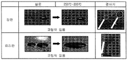
- FIG. 9 shows a comparison result in the case where the oil causing the contaminants extracted from the workpiece is dipped in each of the SUS304 on which the coating film 43 is formed on the surface and the glass plate on which the coating film 43 is not formed.
- the coating film 43 can exhibit substantially the same antifouling effect even if it is formed on the glass or the steel sheet 41. Able to know.
- the coating film which concerns on this invention is not limited to what was shown to the Example and each modified example, and may have other composition. More specifically, the coating film may be one that does not contain fluorine such as Teflon, and the liquid repellency may not be lost due to thermal denaturation even when it is around 350 ° C to be reached during cooking.
- the thickness of the coating film is 0.2 ⁇ m or more and 3 ⁇ m or less, generation of cracks or the like can be suppressed, and durability against repeated thermal loads can be realized at a level without problems in use.
- the coating film which concerns on this invention can be used also in any of an electric oven and a gas oven.
- At least one of hexane, heptane, octane, butyl acetate, PEGMEA, and ethyl acetate is used as the solvent, and the weight ratio of the coating material to the solution is combined to be 12.5%.
- the solution is applied to the inner wall 4 of the cooking chamber using a spray gun having a nozzle diameter of 0.5 mm.
- spray gun having a nozzle diameter of 0.5 mm.
- the coating film 43 is heated on the surface of the cooking chamber inner wall 4 for the first predetermined time at a first temperature, and then for a second predetermined time at a second temperature which is higher than the first temperature. It is heated and hardened.
- the base material on which the coating film 43 is formed was the enamel 42, but for example, the coating film 43 may be formed on the surface of the steel sheet such as SUS304. Moreover, you may form the coating film 43 on the inner surface of the viewing window provided in the door 3. Thus, when the base material on which the coating film 43 is formed is other than the enamel 42, what is necessary is just to make it different from the case where the density
- the coating film which concerns on this invention is not limited to what was shown to the Example and each modified example, and may have other composition. More specifically, the coating film does not need to contain fluorine, and even if it is around 320 degreeC reached
- the thickness of the coating film is 0.2 ⁇ m or more and 3 ⁇ m or less, generation of cracks or the like can be suppressed, and durability against repeated thermal loads can be realized at a level without problems in use.
- the coating film which concerns on this invention can be used also in any of an electric oven and a gas oven.
- the oven 100 according to the second embodiment of the present invention will be described with reference to the drawings. Although the oven 100 according to the second embodiment is the same as that of FIG. 1, the operations of the vibrator 7 and the heater mechanism 5 are different from those of the oven 100 according to the first embodiment.
- the vibrator 7 is a vibration in which one end is excited by the eccentric motor 71 (refer FIG. 1) and the eccentric weight of the eccentric motor 71, and the other end becomes a drive shaft connected to the outer side surface of the inner wall of the cooking chamber 4. It consists of the transfer plate 72 (refer FIG. 1). More specifically, the vibration frequency of the eccentric motor 71 changes according to the magnitude of the input current.
- the eccentric motor 71 is in contact with the face plate portion of the eccentric additional vibration transfer plate 72 in a direction perpendicular to the vibration and moves in the vertical direction.
- the vibration transmission plate 72 is connected to the cooking chamber inner wall 4 and is provided so as not to contact the main body 2. That is, the vibration generated in the vibrator 7 is not transmitted to the main body 2.
- the vibration transmission plate 72 is connected to the back surface which extends up and down among the cooking chamber inner walls 4, and the bending vibration of the vibration transmission plate 72 in the up-down direction is transmitted.
- the control board 8 controls the heater mechanism 5, the vibrator 7, and the motor 62 to control different operations at least in the cooking mode and the cleaning mode.
- the control board 8 is a so-called computer provided with a CPU, a memory, an A / D / D / A converter, and the like, and the oven program stored in the memory is executed to cooperate with various devices to at least the heater mechanism. It functions as a control part, a vibrator control part, and a fan control part.
- the heater mechanism controller controls the current flowing to each of the upper heater 51, the lower heater 52, and the rear heater 53 constituting the heater mechanism 5 so as to maintain the temperature in the cooking chamber 1 at the set temperature.
- the heater mechanism control unit controls the heater mechanism 5 to maintain the temperature in the cooking chamber 1 at a temperature suitable for cooking of the workpiece.
- the heater mechanism control unit controls the heater mechanism 5 to hold the inside of the cooking chamber 1 at a predetermined temperature which makes it easy to move the droplets attached to the cooking chamber inner wall 4 by vibration by the vibrator 7. To control.
- the fan control unit controls the amount of air in the cooking chamber 1 generated by the fan 61 by controlling the rotation speed of the motor 62 when the heating by the heater mechanism 5 is being performed. Convection in the cooking chamber 1 generated by the pan 61 causes only a part of the cooking chamber 1 to become high temperature so that the liquid repellency of the coating film 43 is not lost.
- the control board 8 enters the cleaning mode when the cooking mode ends.
- the vibrator control part vibrates the vibrator 7 in the predetermined amplitude range and the predetermined frequency range, and vibrates the cooking chamber inner wall 4 in the vertical direction.
- the predetermined amplitude range is attached on the coating film 43, and the vibration sound of the inner wall 4 of the cooking chamber from the main body 2 to the outside is supplied at a predetermined level while supplying the force required to move the minute droplets that do not fall off by its own weight. Set it to a value that will not leak.
- the predetermined frequency range is set to include the resonance frequency of the droplet determined according to the size of the droplet attached to the inner wall 4 of the cooking chamber.
- the predetermined amplitude range is set to 10 ⁇ m or more and 100 ⁇ m or less
- the predetermined frequency range is set to 20 Hz or more and 220 Hz or less.
- the vibration control unit controls the vibrator 7 to continuously vibrate the cooking chamber inner wall 4 within 10 seconds to 60 seconds.
- the heater mechanism control unit When vibrating the vibrator 7 in the cleaning mode, the heater mechanism control unit also operates the heater mechanism 5 to perform temperature control to maintain the inside of the cooking chamber 1 at a predetermined temperature.
- the heater mechanism 5 maintains the temperature inside the cooking chamber 1 at a temperature higher than room temperature in the cleaning mode. More specifically, in the cleaning mode, the interior of the cooking chamber 1 is maintained at 60 ° C or higher and 350 ° C or lower.
- the vibrator 7 and the heater mechanism 5 cooperate, and it demonstrates based on experimental data that the microdroplets which continue to adhere can be dropped even if there is liquid repellency of the coating film 43.
- 1.0 ⁇ L, 1.5 ⁇ L, 2.0 ⁇ L, 2.5 ⁇ L, 3.0 ⁇ L, 3.5 ⁇ L of water droplets are attached to the standing surface of the inner wall of the cooking chamber 4, and then the micro vibrator 7 performs the micro vibration. It occurred at room temperature. Specifically, the waveform of the sinusoidal wave whose frequency changes from 20 Hz to 120 Hz for 10 seconds by the vibrator 7 was added three times. As a result, water droplets could be moved as shown in FIG. 10B.
- 1.0 ⁇ L, 1.5 ⁇ L, 2.0 ⁇ L, 2.5 ⁇ L, 3.0 ⁇ L, 3.5 ⁇ L of oil droplets are adhered to the standing surface of the inner wall of the cooking chamber 4, and then the micro vibrator 7 performs the micro vibration. It occurred for each when it kept at 60 degreeC by room temperature and the heater mechanism 5. Specifically, the waveform of the sinusoidal wave whose frequency changes from 20 Hz to 120 Hz for 10 seconds by the vibrator 7 was added three times. As a result, the oil droplets could not be moved even at room temperature, but the oil droplets could be moved as shown in FIG. 11B when the temperature in the cooking chamber 1 was maintained at 60 ° C.
- Droplets Temperature Droplet diameter Waveform Modulation Conditions Moving distance Droplets Room temperature About 0.5mm Change sine wave of 20Hz-120Hz in ten seconds 1mm or less 0.8 mm 2 mm 1.0 mm 10mm or more Drops of oil (oil collected after cooking chicken) Room temperature About 0.5mm Sine wave of 20Hz-220Hz changes in 20 seconds Not moving 0.8 mm 1.0 mm 60 About 0.5mm Sine wave of 20Hz-220Hz changes in 20 seconds 1mm or less 0.8 mm 2 mm 1.0 mm 5 mm
- the inner wall 4 of the cooking chamber is opened by the vibrator 7.
- the vibrator 7 By vibrating minutely in the up and down direction, droplets containing minute water droplets or oil droplets can be moved out of the cooking chamber inner wall 4 and eliminated.
- the inner wall 4 of the cooking chamber is vibrated by the vibrator 7 while maintaining the temperature inside the cooking chamber 1 by the heater mechanism 5 at 60 ° C. or higher.
- the vibrator 7 may be vibrated to move the oil droplets.
- the temperature inside the cooking chamber 1 in the cleaning mode may be appropriately set or may be set to a temperature other than 60 ° C.
- the temperature in the cooking chamber 1 may be set in a temperature range in which the coating film 43 does not lose its liquid repellency due to thermal modification.
- the vibrator 7 is not limited to being operated by an eccentric motor, and various ones such as an electromagnetic vibrator and a piezoelectric element can be used. Moreover, the vibration direction by the vibrator 7 should just contain at least a vertical direction, and may contain other vibration direction components. Moreover, about the predetermined frequency range which vibrates the vibrator 7, you may set according to the magnitude
- the predetermined frequency range is not limited to that shown in the above embodiment, but may be appropriately set according to parameters such as the size of the oven, the size of the inner wall of the cooking chamber, the sound insulation performance, the length of time for oscillating the oscillator, and the like.
- the vibration by the vibrator 7 is not limited to being continuously applied, but may be applied intermittently. For example, a rest period may be provided each time the frequency of the vibrator is changed.
- the oven 100 of the third embodiment does not include the vibrator 7 as compared with the ovens 100 of the first and second embodiments, and the control board according to the cleaning mode ( It differs in the structure of 8).
- control board 8 (control unit) has a predetermined holding time for a state in which the temperature of the cooking chamber inner wall 4 is 350 ° C. or more and 400 ° C. or less in a cleaning mode for dropping contaminants attached to the cooking chamber inner wall 4. It is comprised so that the fan 61 may be driven simultaneously, driving the heater mechanism 5 so that it may continue abnormally. That is, unlike the conventional pyro cleaning, the pan 61 is driven when the inside of the cooking chamber 1 and the inner wall 4 of the cooking chamber are brought to a high temperature. Moreover, the temperature of the inside of the cooking chamber 1 and the inside wall of the cooking chamber 4 is raised only to the temperature lower than 420 degreeC which is conventionally needed when dropping a contaminant.
- the fan 61 and the upper heater 51, the lower heater 52, and the rear heater 53 each have a control board (for one hour or more, which is a predetermined holding time). 8).
- the fan 61 is always driven, and the air flow is always formed inside the cooking chamber 1 to make the temperature uniform.
- Each heater constituting the heater mechanism 5 is configured to perform periodic ON / OFF control. More specifically, the upper heater 51 and the lower heater 52 are alternately driven so that their ON timings do not overlap. More specifically, the upper heater 51 is configured to periodically perform ON / OFF control in which the ON state is set to 20 seconds and the OFF state is set to 32 seconds in one cycle.
- the lower heater 52 periodically performs ON / OFF control in which the ON state is 10 seconds and the OFF state is 42 seconds in one cycle.
- the phases of the control cycles of the upper heater 51 and the lower heater 52 are shifted, and the ON state of the lower heater 52 is started from the time when the ON state of the upper heater 51 is finished.
- the rear heater 53 is configured to periodically perform ON / OFF control such that the ON state is 40 seconds and the OFF state is 12 seconds in one cycle.
- the ON state of the rear heater 53 is coincident with the start of the ON state of the upper heater 51. Therefore, while the upper heater 51 and the lower heater 52 are turned ON alternately, the rear heater 53 is always ON. In addition, every 40 seconds, all the heaters are turned off for 12 seconds.
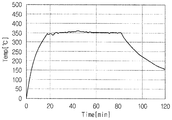
- FIG. 14 is a graph showing results obtained by measuring temperature change over time by providing a temperature sensor on each surface of the inner wall of the cooking chamber.
- FIG. 15 shows the results obtained by measuring the temperatures of the cooking chamber 1 and the cooking chamber inner wall 4 by thermography.
- the temperature of each standing surface in the cooking chamber inner wall 4 gradually rises from the start of the cleaning mode, and finally, all surfaces of the cooking chamber inner wall 4 are 385 ° C to 400 degrees. It can be seen that it is maintained in a substantially uniform state at °C.
- FIG. 16A shows a state in which contaminants before cleaning adhere to the cooking chamber inner wall 4 in spot form.
- FIG. 16B shows a state in which contaminants before cleaning adhere to the cooking chamber inner wall 4 in spot form.
- At least 1 m / s or more of air flow is formed by the fan 61 at the position 1 cm from the standing surface of the cooking chamber inner wall 4, as shown in FIG.
- the control of the heater mechanism 5 and the fan 61 is not limited to the above description, and feedback control based on the output of measurement sensors such as PWM control and temperature sensors may be performed. Further, as shown in the third embodiment, it is easy to realize the simplification and the cost reduction of the oven by performing the feed forward control.
- the vibrator 7 in the first and second embodiments may further apply the micro vibrations caused by the vibrator 7 to the cooking chamber inner wall 4 in the cleaning mode.
- the oven 100 is comprised so that the to-be-cooked object may be accommodated in the cooking chamber 1 and the to-be-cooked object is heated by the heater mechanism 5.
- the oven 100 may include a main body 2 forming an appearance.
- the main body 2 may have a shape of a substantially fused facet body in which a front face is opened.
- the oven 100 may further include a cooking chamber 1 provided inside the main body 2.
- the cooking chamber 1 may have a substantially rectangular parallelepiped shape in which a front surface is opened.
- the cooking chamber 1 may be defined by the cooking chamber inner wall 4.
- the cooking chamber inner wall 4 may include an upper surface 4a, a lower surface 4b, a right side, a left side, and a rear side 4c.
- the oven 100 may further include a door 3 rotatably installed in the main body 2 to open and close the cooking chamber 1.
- the door 3 may be provided with a viewing window so that the state inside the cooking chamber 1 can be checked from the outside.
- the oven 100 may further include a heater mechanism 5 installed in the cooking chamber 1 or in the vicinity of the cooking chamber 1.
- the oven 100 may further include a fan 61 installed to convection or circulate the air heated by the heater mechanism 5.
- the oven 100 may further include a control mechanism 8 that is responsible for controlling the heater mechanism 5 and the motor 62 that drives the fan 61.
- the heater mechanism 5 includes an upper heater 51 installed at the upper part of the cooking chamber 1, a lower heater 52 provided at the lower part of the cooking chamber 1, and a fan 61 at the rear side in the cooking chamber 1. It consists of a rear heater 53 installed.
- the upper heater 51 and the rear heater 53 may be installed to be exposed inside the cooking chamber 1, and the lower heater 52 may be installed to be located between the cooking chamber 1 and the main body 2. That is, the lower heater 52 may be installed to be located outside the inner wall 4 of the cooking chamber and inside the main body 2.
- the upper heater 51 corresponds to the main heater.
- the oven 100 may further include a heat insulator 9 disposed between the cooking chamber 1 and the main body 2. That is, the heat insulating material 9 may be disposed between the outer surface of the cooking chamber inner wall 4 and the inner surface of the main body 2. In addition, the heat insulator 9 may be arranged inside the door 3.
- the oven 100 may further include a coating film 43 formed on at least a portion of the inner wall of the cooking chamber.
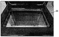
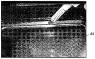
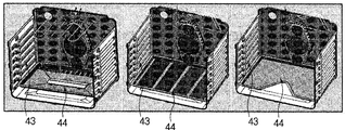
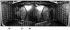
- the oven 100 may include a contaminant collecting portion 44 formed on at least a portion of the inner wall of the cooking chamber. It may further include.
- a coating layer 43 may be formed on a portion of the inner wall of the cooking chamber 4, and a contaminant collecting portion 44 may be formed on the remaining portion of the inner wall of the cooking chamber 4.
- the heater mechanism 5, the fan 61, and the control board 8 can cooperate with each other to control the temperature inside the cooking chamber 1 or its temperature distribution.
- the cooking mode in which the temperature of the cooking chamber inner wall 4 reaches about 350 ° C. is maintained at a temperature higher than the cooking mode for a predetermined time, and the convection of air in the cooking chamber 1 is controlled.
- a cleaning mode for removing contaminants adhering to the inner wall 4 of the cooking chamber is configured.
- the coating film 43 is to have a liquid-repellent surface energy is one having a 0mJ / m 2 more than 20mJ / m 2 or less characteristic.
- the contaminant collecting portion 44 is smaller in liquid repellency than the coating film 43 and has a surface energy of 25 mJ / m 2 or more.
- the difference of the surface energy of each surface is set to 5 mJ / m ⁇ 2> or more.
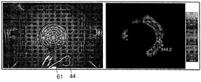
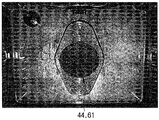
- the contaminant collecting unit 44 may be provided at a portion where the circulation of the hot air formed in the cooking chamber 1 by the pan 61 first moves. In other words, the contaminant collecting unit 44 may be provided at a portion where air circulating inside the cooking chamber 1 is first collided by the pan 61.
- the contaminant collecting portion 44 is formed to collect the minute oil droplets. That is, the contaminant collecting part 44 may be formed on the rear surface 4c of the cooking chamber inner wall 4.
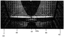
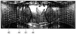
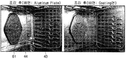
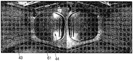
- the coating film 43 is formed on the left side of the rear surface of the cooking chamber inner wall 4, and the coating layer 43 is not formed on the right side of the rear surface of the cooking chamber.
- Raw chicken meat was baked at 230 ° C. for 1 hour as a food. This cooking was repeated until the total number of raw chicken meat reached 20, and the subsequent contamination of the inner wall 4 of the cooking chamber was observed.
- the grease is hardly present in the left portion of the rear surface where the coating film 43 is formed, but the grease concentration is concentrated in the contaminant collecting portion 44.
- the coating film 43 is not formed on the inner wall of the cooking chamber, and instead of forming the contaminant collecting portion 44, a metal plate on which the coating film 43 is not formed is detachably attached to the cooking chamber 1. It is configured to deploy.
- the pan 61 is arrange
- the contaminant collecting portion 44 is a body 44a detachably installed at one side of the inner wall of the cooking chamber 4 and a groove through which liquid oil collected on the surface of the body 44a flows downward by gravity ( 44b) and a waste liquid receiver 44e provided below the groove 44b to collect oil as waste liquid.
- the body 44a may be formed of a metal plate.
- the body 44a may be formed of an aluminum plate.
- the groove 44b may be inclined so that oil collected in the groove 44b can smoothly move to the waste liquid receiving 44e side.
- the guide 44b may be formed in the body 44a to guide contaminants attached to the surface of the body 44a to the lower side of the cooking chamber 1 as shown in FIG. 25.
- the handle 44c may be formed on the body 44a so as to easily mount or detach the contaminant collecting portion 44.
- the oven 100 of the first modified example is subjected to the same experiment as in FIGS. 21 to 23. The contaminants in the oven 100 were confirmed. As shown in FIG. 27, since the minute oil is absorbed into the detachable contaminant collecting portion 44, the contaminant in the form of minute spots is formed on the coating film 43 on the side surface of the cooking chamber inner wall 4. It does not occur and cleanliness is maintained.
- the spot-type contaminants can be prevented from being deposited on the coating film 43 even after long-term use by the minute oil collection effect of the contaminant collecting portion 44,
- the contaminant collecting portion 44 in which contaminants are collected can be removed from the cooking chamber 1 and easily cleaned. Therefore, the oil collection effect by the dirt collection part 44 can be simply reversed, and the ability to maintain the cleanliness of the cooking chamber inner wall 4 is exhibited continuously.
- the above-described contaminant collecting unit 44 since the softness generated from the cooked material is absorbed, even if the door is opened during cooking, the amount of softening discharged to the outside can be reduced.
- the cooking is performed under the same conditions and the door is opened at the same time. The difference in softening amount is shown.
- the oven 100 having the contaminant collecting unit 44 on the left side of FIG. 29 has a smaller amount of softness discharged to the outside than the oven 100 having no contaminant collecting unit 44 on the right side.
- the contaminant collecting portion 44 has stood in the cooking chamber 1, but for example, as shown in FIG. 32, the water-repellent coating film 43 at the bottom end of the cooking chamber 1 of the oven 100 is shown. You may arrange
- the oil which protruded from the to-be-cooked object can be prevented from contaminating the lower surface of the cooking chamber 1, and it can pick up also about the oil which falls.
- the metal tray may be removed so that it does not interfere with baking.
- the fourth modification is the oven 100 in which the catalyst coating layer is formed as the contaminant collecting portion 44.
- the contaminant collecting portion 44 may include a catalyst coating layer.
- the catalyst coating layer is a contaminant collecting portion 44 by applying a thermal catalyst to a detachable part in the oven 100. Specifically, Ag and MnO 2 as cocatalysts are used as catalyst materials.
- a low molecular weight Silane coating agent including a Silane coupling agent, Vinyl-Siloxane, Ethoxy-Aluminaphosphate and Alkyl-Aryl Siloxane, PerHydro-Polysilazane (PHPS) or Organo-Polysilazane (OPSZ)
- PHPS PerHydro-Polysilazane
- OPSZ Organo-Polysilazane
- the main component of the catalyst may be a substance containing at least one or more of noble metals and various catalyst metals (Ag, Pt, Pd, Au, Cu, Ru, Ti, Ni) and these metal elements.
- various catalyst metals Au, Cu, Ru, Ti, Ni
- metal oxides MnO 2, CeO 2, Al 2 O 3, Bi 2 O 3, SnO, TiO 2, Cr 2 O 3, Co 2 O 3, Fe 2 O 3, CuO, ZrO 2, SrO, LaO, V 2 O 5, Li 2 O, ZnO, MgO, NiO, CuO, BaO
- the compound containing one or more types may be included.
- the catalyst coating layer comprises a catalyst comprising at least one of Ag, Pt, Pd, Au, Cu, Ru, Ti, and Ni, and MnO 2 , CeO 2 , Al 2 O 3 , Bi 2 O 3 , SnO, TiO 2 ,
- a bath comprising at least one of Cr 2 O 3 , Co 2 O 3 , Fe 2 O 3 , CuO, ZrO 2 , SrO, LaO, V 2 O 5 , Li 2 O, ZnO, MgO, NiO, CuO and BaO It may include a catalyst.
- a pan 61 is provided, and a plurality of vanes standing vertically are provided to the cooking chamber inner wall 4 forming the rear surface of the cooking chamber 1, and a contaminant collecting portion is provided. (44).
- the vanes are formed convexly with respect to the outer circumferential direction of the pan, and stand up against the inner wall of the cooking chamber 4 provided around the pan 61, and the air flow discharged from the pan 61 follows the vanes from the centrifugal direction. It is comprised so that it may gradually deflect in the tangential direction.
- the contaminant collecting portion 44 is provided along the outer circumferential direction of the fan 61 so as to gradually deflect the air flow discharged from the fan 61 from the centrifugal direction of the fan 61 in the tangential direction of the fan 61. It may include a plurality of vanes. More specifically, as shown in FIG. 35, each vane is radially disposed by a spiral curve around the fan 61. Each vane is arranged at substantially equal intervals in the circumferential direction. In addition, the size and length of each vane are calculated by integrating the air flow rate with the wind speed distribution of the inlet port, and are designed in consideration of the air resistance so that the conditions are 23 to 26L per second. Each vane is accommodated in the case at the time of use, as shown in Fig. 36, so that it is invisible to the user.
- vanes having different lengths in the flow direction may be arranged as shown in FIG. More specifically, long vanes and short vanes may be alternately arranged along the circumferential direction of the fan 61. 38 shows a contamination state when 20 raw chickens are cooked when such a vane is used. As can be seen by comparing FIG. 36 with FIG. 38, a vane having a different length in the air flow direction is provided with a side surface of the inner wall of the cooking chamber 4 corresponding to the periphery of the pan case than when the same vanes are disposed radially. Less amount of dirt attached to the back.
- the collection area is increased, the separation effect of the flexion is increased from the improvement of the rectification effect of the airflow, and the airflow falls between the vanes at the outer periphery where the distance from the center is increased. It can be seen that the capture effect works.
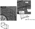
- a plurality of protrusions 44j having a substantially triangular shape are provided between the vanes as a vortex generator along the air flow direction.
- the protrusion 44j may be provided bent.
- the protrusion 44j generates a vortex in the air stream and collides with the vane, so that the oil droplets contained therein are easily collected in the vane.
- the left figure of FIG. 40 shows the position of the vortex generator, ie, the projection 44j, in the entire quarter of the area.
- the figure in the center shows the bending position.
- the figure on the right shows the planar dimension of the bend.
- the detailed dimensions are determined by the relationship between the wind speed, the path width, and the vane spiral curve, but are determined as shown in consideration of workability. However, it is not limited to the dimension shown.
- the vortex generator that is, the projection 44j is formed, as shown in FIG. 41, the collection effect such as micro oil droplets in the vane is further enhanced, and as a result, adhesion of grease to the cooking chamber inner wall 4 is further prevented. can do.
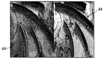
- FIG. 42 shows the difference in the collection effect of contaminants with or without the vortex generator, that is, the projection 44j.
- a vortex generator ie, projection 44j is absent, and a support plate is planar
- the right figure shows an example of the case where a vortex generator, ie projection 44j, is provided.
- the installation of the vortex generator collects a lot of contaminants, and contaminants are also attached to the back side of the bent triangle plate (a surface that can be seen with the eyes in the photograph on the downstream side of the wind). do. Therefore, it can be seen that the installation position and the number of installations of the vortex generator can change and increase or decrease depending on the optimization.
- FIG. 43 shows an unused state in which an oven 100 having a contaminant collecting portion 44 composed of a vortex generator and vanes is provided with a catalyst coating layer around the vanes.
- the catalyst is composed of a metal (Ag, Pt, Pd, Au, Cu, Ru, Ti, Ni) and at least one of these metal elements. In this example, Pt is used.
- FIG. 44 shows the state of time when 20 raw chickens were cooked
- FIG. 45 shows the state when 40 raw chickens were cooked. It can be seen from each figure that the presence of the catalyst coating layer does not lower the effect of collecting contaminants over a long period of time, and thus the cleanliness of the inner wall of the cooking chamber 4 is increased. In particular, it can be seen from FIG. 44 that overwhelmingly less than 20 contaminants after cooking without the catalyst coating layer. Therefore, it can be seen that by forming the catalyst coating layer, the ability to collect contaminants is improved at least twice. Moreover, in order to fully exhibit the effect
- the control board 8 operates the heater mechanism 5 in order to heat the catalyst coating layer, and controls ON / OFF of the fan 61.
- part on which the catalyst coating layer was formed is heated to the temperature range of 250 degreeC or more and 400 degrees C or less.
- the control board 8 has a function of lowering the duty of the pan at the time of cleaning than the duty of the pan at the time of normal cooking.
- the cycle of ON / OFF control may be 5 seconds to 60 seconds, and the duty of ON may be 16% to 20%.
- the effect of contaminant decomposition was confirmed under the above conditions.
- Fan behavior OFF ON 10 seconds / 60 seconds ON: 1 second / 5 seconds ON: 0.5 sec / 5 sec Fan case surface temperature 280 or more 280 or more 280 or more 280 or more Fan case surface temperature and high temperature Set temperature difference 60 or more 60 or more 60 or more 60 or more Internal vane temperature About 220 It fluctuates to approximately 230-260 Approximately 270 About 220 Fan case surface temperature and high set temperature difference radish 10-50 About 50 radish Fluctuation of Internal Vane Temperature radish U radish radish Decontamination of contaminants on the fan case surface possible possible possible possible possible Decomposition of contaminants in the inner vanes Impossible Possible (low efficiency) possible Impossible
- the catalyst materials described above that is, noble metals (Ag, Pt, Pd, Au, Cu, Ru, Ti, Ni) and those containing at least one or more of these metal elements, in particular, Even if it does not contain Pt, it can clean in a normal normal operation mode.
- the temperature is 400 ° C. or less.
- An example of the decomposition of grease in the table is shown.
- the oil spot which adhered on the surface of an enamel as a comparison object with a catalyst surface was produced
- the temperature environment in the cooking chamber 1 was realized with the temperature profile shown in FIG. 47, and the decomposition rate at the time of oil was compared on the conditions. 47 shows the case where the set temperature in the cooking chamber 1 is 350 ° C.
- the ON / OFF control of the heater mechanism 5 minimizes and confirms the temperature fluctuation when the temperature is maintained at a high temperature. However, if the average temperature is the same even if there is a fluctuation, it is expected that no large difference occurs in the result.
- the entire interior of the cooking chamber 1 is not heated, but only the portion where the catalyst coating layer is formed is locally heated during cooking to decompose contaminants. That is, it is possible to maintain the cleanliness of the inner wall 4 of the cooking chamber for a long time without executing the cleaning mode, which consumes a lot of power and takes time.
- FIG. 50 only a part of nichrome wire reaches 380 degreeC as an experiment. As shown in the left figure of FIG. 50, it can be seen that contaminants are decomposed and cleanliness is maintained in the heated portion.
- the catalytic coating layer heating heater is brought close to the portion where the catalyst coating layer is formed, so that the decomposition reaction occurs even during heating cooking.
- the distance between them is designed to be 1 mm or less.
- the oven 100 may further include a catalyst coating layer heating heater installed in the cooking chamber 1 to heat the catalyst coating layer.
- a seventh modification of the fourth embodiment of the present invention will be described.
- a member having a large specific surface area and no liquid repellency is disposed in the flow path of the air flow formed by the pan 61 in the cooking chamber 1.
- a filter is arrange
- the catalyst coating layer described above in such a filter, the contaminants accumulated in the contaminant collecting portion 44 can be decomposed to prevent the minute oil deposits on the coating film 43 for a long time.
- the contaminant collecting unit 44 may include a filter disposed at at least one of the inlet and outlet of the fan 61.
- the filter may be arranged at the inlet of the fan 61.
- a porous material may be sufficient as a filter, and what is necessary is just to select suitably about a catalyst coating layer.
- the filter may be formed of at least one of a porous material and a fiber material.
Landscapes
- Chemical & Material Sciences (AREA)
- Engineering & Computer Science (AREA)
- Combustion & Propulsion (AREA)
- Mechanical Engineering (AREA)
- General Engineering & Computer Science (AREA)
- Life Sciences & Earth Sciences (AREA)
- Materials Engineering (AREA)
- Wood Science & Technology (AREA)
- Organic Chemistry (AREA)
- Chemical Kinetics & Catalysis (AREA)
- Inorganic Chemistry (AREA)
- Electric Stoves And Ranges (AREA)
- Electric Ovens (AREA)
Abstract
Priority Applications (3)
| Application Number | Priority Date | Filing Date | Title |
|---|---|---|---|
| KR1020187012677A KR102641378B1 (ko) | 2016-02-12 | 2017-02-10 | 오븐 |
| EP17750473.5A EP3399240B1 (fr) | 2016-02-12 | 2017-02-10 | Four |
| US16/077,428 US10670277B2 (en) | 2016-02-12 | 2017-02-10 | Oven |
Applications Claiming Priority (10)
| Application Number | Priority Date | Filing Date | Title |
|---|---|---|---|
| JP2016-024939 | 2016-02-12 | ||
| JP2016024939 | 2016-02-12 | ||
| JP2016-027667 | 2016-02-17 | ||
| JP2016027669 | 2016-02-17 | ||
| JP2016-027669 | 2016-02-17 | ||
| JP2016027667 | 2016-02-17 | ||
| JP2016-091953 | 2016-04-28 | ||
| JP2016091953 | 2016-04-28 | ||
| JP2017010770A JP2017201232A (ja) | 2016-02-12 | 2017-01-24 | オーブン装置 |
| JP2017-010770 | 2017-01-24 |
Publications (1)
| Publication Number | Publication Date |
|---|---|
| WO2017138781A1 true WO2017138781A1 (fr) | 2017-08-17 |
Family
ID=59563936
Family Applications (1)
| Application Number | Title | Priority Date | Filing Date |
|---|---|---|---|
| PCT/KR2017/001500 Ceased WO2017138781A1 (fr) | 2016-02-12 | 2017-02-10 | Four |
Country Status (1)
| Country | Link |
|---|---|
| WO (1) | WO2017138781A1 (fr) |
Cited By (2)
| Publication number | Priority date | Publication date | Assignee | Title |
|---|---|---|---|---|
| CN113100637A (zh) * | 2021-04-30 | 2021-07-13 | 广州富港万嘉智能科技有限公司 | 智能烹饪设备的清洁控制方法及装置、智能橱柜 |
| US11519073B1 (en) * | 2019-10-09 | 2022-12-06 | Lincoln Industries, Inc. | Sol-gel coated oven and coating process |
Citations (5)
| Publication number | Priority date | Publication date | Assignee | Title |
|---|---|---|---|---|
| US20030213792A1 (en) * | 2002-04-23 | 2003-11-20 | Cleveland Range | Method and steaming oven and collector plate |
| KR20070091635A (ko) * | 2004-12-03 | 2007-09-11 | 터보쉐프 테크놀러지즈, 아이엔씨. | 고속 대류 오븐 |
| US20090266243A1 (en) * | 2006-10-10 | 2009-10-29 | Seong Bin Lee | Cooking apparatus and cleaning method for the same |
| KR20100087625A (ko) * | 2009-12-29 | 2010-08-05 | 주식회사 넥터스 | 진공 공간을 이용한 요리용 및 보온용 오븐 |
| US20130178568A1 (en) * | 2012-01-06 | 2013-07-11 | The United States Of America As Represented By The Secretary Of The Air Force | Liquid repellent surfaces |
-
2017
- 2017-02-10 WO PCT/KR2017/001500 patent/WO2017138781A1/fr not_active Ceased
Patent Citations (5)
| Publication number | Priority date | Publication date | Assignee | Title |
|---|---|---|---|---|
| US20030213792A1 (en) * | 2002-04-23 | 2003-11-20 | Cleveland Range | Method and steaming oven and collector plate |
| KR20070091635A (ko) * | 2004-12-03 | 2007-09-11 | 터보쉐프 테크놀러지즈, 아이엔씨. | 고속 대류 오븐 |
| US20090266243A1 (en) * | 2006-10-10 | 2009-10-29 | Seong Bin Lee | Cooking apparatus and cleaning method for the same |
| KR20100087625A (ko) * | 2009-12-29 | 2010-08-05 | 주식회사 넥터스 | 진공 공간을 이용한 요리용 및 보온용 오븐 |
| US20130178568A1 (en) * | 2012-01-06 | 2013-07-11 | The United States Of America As Represented By The Secretary Of The Air Force | Liquid repellent surfaces |
Cited By (2)
| Publication number | Priority date | Publication date | Assignee | Title |
|---|---|---|---|---|
| US11519073B1 (en) * | 2019-10-09 | 2022-12-06 | Lincoln Industries, Inc. | Sol-gel coated oven and coating process |
| CN113100637A (zh) * | 2021-04-30 | 2021-07-13 | 广州富港万嘉智能科技有限公司 | 智能烹饪设备的清洁控制方法及装置、智能橱柜 |
Similar Documents
| Publication | Publication Date | Title |
|---|---|---|
| WO2016024691A1 (fr) | Aspirateur | |
| EP3551334A1 (fr) | Appareil électronique de collecte de poussière et procédé de fabrication de collecteur de poussière | |
| EP3399240B1 (fr) | Four | |
| WO2013047975A1 (fr) | Appareil d'éclairage à base de semi-conducteurs optiques | |
| WO2019139359A1 (fr) | Purificateur d'eau et son procédé de commande | |
| WO2017171501A1 (fr) | Appareil de nettoyage | |
| WO2017074140A1 (fr) | Dispositif d'humidification et de purification | |
| WO2018143704A1 (fr) | Composition de verre et équipement de cuisson | |
| WO2022231089A1 (fr) | Hotte portative | |
| WO2019146923A1 (fr) | Dispositif de nettoyage | |
| WO2014088233A1 (fr) | Appareil chauffant pour chauffant instantané de l'eau | |
| WO2022244945A1 (fr) | Hotte portatible | |
| WO2024167130A1 (fr) | Dispositif de nettoyage et procédé de commande de dispositif de nettoyage | |
| WO2024096252A1 (fr) | Purificateur d'air | |
| WO2017074132A1 (fr) | Dispositif d'humidification et de nettoyage | |
| WO2017030315A1 (fr) | Support d'échantillon pour appareil de dépôt, et appareil de dépôt comportant ledit support d'échantillon | |
| US10654069B2 (en) | Coating of usage surfaces with plasma polymer layers under atmospheric pressure in order to improve the cleanability | |
| WO2023008896A1 (fr) | Dispositif de nettoyage | |
| WO2022250494A1 (fr) | Four à micro-ondes | |
| WO2024162601A1 (fr) | Purificateur d'eau et appareil électroménager ayant une fonction de décharge d'eau | |
| WO2023128180A1 (fr) | Matériau intérieur d'appareil de cuisson, appareil de cuisson et procédé d'élimination de taches de celui-ci | |
| WO2025206573A1 (fr) | Climatiseur et son procédé de commande | |
| WO2026029397A1 (fr) | Appareil de cuisson et procédé de commande associé | |
| WO2025018524A1 (fr) | Appareil de cuisson | |
| WO2025100795A1 (fr) | Appareil de cuisson et son procédé de commande |
Legal Events
| Date | Code | Title | Description |
|---|---|---|---|
| 121 | Ep: the epo has been informed by wipo that ep was designated in this application |
Ref document number: 17750473 Country of ref document: EP Kind code of ref document: A1 |
|
| ENP | Entry into the national phase |
Ref document number: 20187012677 Country of ref document: KR Kind code of ref document: A |
|
| WWE | Wipo information: entry into national phase |
Ref document number: 2017750473 Country of ref document: EP |
|
| NENP | Non-entry into the national phase |
Ref country code: DE |
|
| ENP | Entry into the national phase |
Ref document number: 2017750473 Country of ref document: EP Effective date: 20180731 |