WO2017141331A1 - Dispositif de joint d'arbre - Google Patents
Dispositif de joint d'arbre Download PDFInfo
- Publication number
- WO2017141331A1 WO2017141331A1 PCT/JP2016/054336 JP2016054336W WO2017141331A1 WO 2017141331 A1 WO2017141331 A1 WO 2017141331A1 JP 2016054336 W JP2016054336 W JP 2016054336W WO 2017141331 A1 WO2017141331 A1 WO 2017141331A1
- Authority
- WO
- WIPO (PCT)
- Prior art keywords
- shaft
- flow path
- side seal
- seal portion
- rotation
- Prior art date
- Legal status (The legal status is an assumption and is not a legal conclusion. Google has not performed a legal analysis and makes no representation as to the accuracy of the status listed.)
- Ceased
Links
Images


Classifications
-
- F—MECHANICAL ENGINEERING; LIGHTING; HEATING; WEAPONS; BLASTING
- F16—ENGINEERING ELEMENTS AND UNITS; GENERAL MEASURES FOR PRODUCING AND MAINTAINING EFFECTIVE FUNCTIONING OF MACHINES OR INSTALLATIONS; THERMAL INSULATION IN GENERAL
- F16K—VALVES; TAPS; COCKS; ACTUATING-FLOATS; DEVICES FOR VENTING OR AERATING
- F16K1/00—Lift valves or globe valves, i.e. cut-off apparatus with closure members having at least a component of their opening and closing motion perpendicular to the closing faces
- F16K1/16—Lift valves or globe valves, i.e. cut-off apparatus with closure members having at least a component of their opening and closing motion perpendicular to the closing faces with pivoted closure-members
- F16K1/18—Lift valves or globe valves, i.e. cut-off apparatus with closure members having at least a component of their opening and closing motion perpendicular to the closing faces with pivoted closure-members with pivoted discs or flaps
- F16K1/20—Lift valves or globe valves, i.e. cut-off apparatus with closure members having at least a component of their opening and closing motion perpendicular to the closing faces with pivoted closure-members with pivoted discs or flaps with axis of rotation arranged externally of valve member
- F16K1/2028—Details of bearings for the axis of rotation
-
- F—MECHANICAL ENGINEERING; LIGHTING; HEATING; WEAPONS; BLASTING
- F16—ENGINEERING ELEMENTS AND UNITS; GENERAL MEASURES FOR PRODUCING AND MAINTAINING EFFECTIVE FUNCTIONING OF MACHINES OR INSTALLATIONS; THERMAL INSULATION IN GENERAL
- F16K—VALVES; TAPS; COCKS; ACTUATING-FLOATS; DEVICES FOR VENTING OR AERATING
- F16K1/00—Lift valves or globe valves, i.e. cut-off apparatus with closure members having at least a component of their opening and closing motion perpendicular to the closing faces
- F16K1/16—Lift valves or globe valves, i.e. cut-off apparatus with closure members having at least a component of their opening and closing motion perpendicular to the closing faces with pivoted closure-members
- F16K1/18—Lift valves or globe valves, i.e. cut-off apparatus with closure members having at least a component of their opening and closing motion perpendicular to the closing faces with pivoted closure-members with pivoted discs or flaps
- F16K1/20—Lift valves or globe valves, i.e. cut-off apparatus with closure members having at least a component of their opening and closing motion perpendicular to the closing faces with pivoted closure-members with pivoted discs or flaps with axis of rotation arranged externally of valve member
-
- F—MECHANICAL ENGINEERING; LIGHTING; HEATING; WEAPONS; BLASTING
- F02—COMBUSTION ENGINES; HOT-GAS OR COMBUSTION-PRODUCT ENGINE PLANTS
- F02D—CONTROLLING COMBUSTION ENGINES
- F02D9/00—Controlling engines by throttling air or fuel-and-air induction conduits or exhaust conduits
- F02D9/04—Controlling engines by throttling air or fuel-and-air induction conduits or exhaust conduits concerning exhaust conduits
-
- F—MECHANICAL ENGINEERING; LIGHTING; HEATING; WEAPONS; BLASTING
- F02—COMBUSTION ENGINES; HOT-GAS OR COMBUSTION-PRODUCT ENGINE PLANTS
- F02D—CONTROLLING COMBUSTION ENGINES
- F02D9/00—Controlling engines by throttling air or fuel-and-air induction conduits or exhaust conduits
- F02D9/08—Throttle valves specially adapted therefor; Arrangements of such valves in conduits
- F02D9/10—Throttle valves specially adapted therefor; Arrangements of such valves in conduits having pivotally-mounted flaps
- F02D9/1005—Details of the flap
- F02D9/1025—Details of the flap the rotation axis of the flap being off-set from the flap center axis
- F02D9/103—Details of the flap the rotation axis of the flap being off-set from the flap center axis the rotation axis being located at an edge
-
- F—MECHANICAL ENGINEERING; LIGHTING; HEATING; WEAPONS; BLASTING
- F02—COMBUSTION ENGINES; HOT-GAS OR COMBUSTION-PRODUCT ENGINE PLANTS
- F02D—CONTROLLING COMBUSTION ENGINES
- F02D9/00—Controlling engines by throttling air or fuel-and-air induction conduits or exhaust conduits
- F02D9/08—Throttle valves specially adapted therefor; Arrangements of such valves in conduits
- F02D9/10—Throttle valves specially adapted therefor; Arrangements of such valves in conduits having pivotally-mounted flaps
- F02D9/1035—Details of the valve housing
- F02D9/106—Sealing of the valve shaft in the housing, e.g. details of the bearings
-
- F—MECHANICAL ENGINEERING; LIGHTING; HEATING; WEAPONS; BLASTING
- F16—ENGINEERING ELEMENTS AND UNITS; GENERAL MEASURES FOR PRODUCING AND MAINTAINING EFFECTIVE FUNCTIONING OF MACHINES OR INSTALLATIONS; THERMAL INSULATION IN GENERAL
- F16K—VALVES; TAPS; COCKS; ACTUATING-FLOATS; DEVICES FOR VENTING OR AERATING
- F16K1/00—Lift valves or globe valves, i.e. cut-off apparatus with closure members having at least a component of their opening and closing motion perpendicular to the closing faces
- F16K1/16—Lift valves or globe valves, i.e. cut-off apparatus with closure members having at least a component of their opening and closing motion perpendicular to the closing faces with pivoted closure-members
- F16K1/18—Lift valves or globe valves, i.e. cut-off apparatus with closure members having at least a component of their opening and closing motion perpendicular to the closing faces with pivoted closure-members with pivoted discs or flaps
- F16K1/20—Lift valves or globe valves, i.e. cut-off apparatus with closure members having at least a component of their opening and closing motion perpendicular to the closing faces with pivoted closure-members with pivoted discs or flaps with axis of rotation arranged externally of valve member
- F16K1/2042—Special features or arrangements of the sealing
- F16K1/2078—Sealing means for the axis of rotation
-
- F—MECHANICAL ENGINEERING; LIGHTING; HEATING; WEAPONS; BLASTING
- F16—ENGINEERING ELEMENTS AND UNITS; GENERAL MEASURES FOR PRODUCING AND MAINTAINING EFFECTIVE FUNCTIONING OF MACHINES OR INSTALLATIONS; THERMAL INSULATION IN GENERAL
- F16K—VALVES; TAPS; COCKS; ACTUATING-FLOATS; DEVICES FOR VENTING OR AERATING
- F16K41/00—Spindle sealings
- F16K41/02—Spindle sealings with stuffing-box ; Sealing rings
- F16K41/08—Spindle sealings with stuffing-box ; Sealing rings with at least one ring provided with axially-protruding peripheral closing-lip
Definitions
- the shaft sealing device may include a biasing member configured to bias the shaft-side seal portion toward the flow path-side seal portion.
- a biasing member configured to bias the shaft-side seal portion toward the flow path-side seal portion.
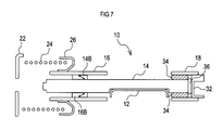
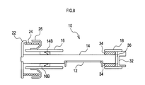
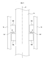
- FIG. 7 is a sectional view taken along the line VII-VII in the shaft seal device before assembly of the urging member. It is sectional drawing in the shaft seal apparatus after the assembly
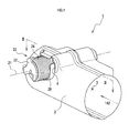
- the shaft seal device 1 includes a flow path pipe 2, a valve 10, and a valve opening / closing mechanism 20.
- the flow channel tube 2 is formed in a cylindrical shape with both ends opened, and a gas flow channel 3 that is a gas flow channel is formed therein.
- the flow path pipe 2 is connected to an exhaust pipe, an exhaust manifold, or the like into which the gas 142 from the internal combustion engine flows.
- the flow path pipe 2 is provided with a through hole 4 that communicates the inside of the gas flow path 3 and the outside of the gas flow path 3. Note that the term “communication” means that a plurality of spaces are connected.
- the rotation-side portion 14 includes the shaft-side seal portion 14 ⁇ / b> B and the flow-path-side seal that protrudes inward along the inner peripheral surface of the first cylindrical portion 16.
- a portion 16B is provided.
- the shaft side seal portion 14 ⁇ / b> B is provided so as to protrude along the outer peripheral portion of the rotating portion 14.
Landscapes
- Engineering & Computer Science (AREA)
- General Engineering & Computer Science (AREA)
- Mechanical Engineering (AREA)
- Chemical & Material Sciences (AREA)
- Combustion & Propulsion (AREA)
- Lift Valve (AREA)
- Sealing Devices (AREA)
- Details Of Valves (AREA)
Abstract
Priority Applications (5)
| Application Number | Priority Date | Filing Date | Title |
|---|---|---|---|
| CN201680055137.4A CN108138989A (zh) | 2016-02-15 | 2016-02-15 | 轴封装置 |
| JP2017567593A JP6633660B2 (ja) | 2016-02-15 | 2016-02-15 | 軸封装置 |
| PCT/JP2016/054336 WO2017141331A1 (fr) | 2016-02-15 | 2016-02-15 | Dispositif de joint d'arbre |
| DE112016006437.3T DE112016006437T5 (de) | 2016-02-15 | 2016-02-15 | Wellendichtungseinrichtung |
| US15/761,627 US20180347706A1 (en) | 2016-02-15 | 2016-02-15 | Shaft Sealing Device |
Applications Claiming Priority (1)
| Application Number | Priority Date | Filing Date | Title |
|---|---|---|---|
| PCT/JP2016/054336 WO2017141331A1 (fr) | 2016-02-15 | 2016-02-15 | Dispositif de joint d'arbre |
Publications (1)
| Publication Number | Publication Date |
|---|---|
| WO2017141331A1 true WO2017141331A1 (fr) | 2017-08-24 |
Family
ID=59624889
Family Applications (1)
| Application Number | Title | Priority Date | Filing Date |
|---|---|---|---|
| PCT/JP2016/054336 Ceased WO2017141331A1 (fr) | 2016-02-15 | 2016-02-15 | Dispositif de joint d'arbre |
Country Status (5)
| Country | Link |
|---|---|
| US (1) | US20180347706A1 (fr) |
| JP (1) | JP6633660B2 (fr) |
| CN (1) | CN108138989A (fr) |
| DE (1) | DE112016006437T5 (fr) |
| WO (1) | WO2017141331A1 (fr) |
Cited By (1)
| Publication number | Priority date | Publication date | Assignee | Title |
|---|---|---|---|---|
| JP2021148212A (ja) * | 2020-03-19 | 2021-09-27 | 株式会社テイエルブイ | 流速制御装置 |
Families Citing this family (3)
| Publication number | Priority date | Publication date | Assignee | Title |
|---|---|---|---|---|
| FR3080427B1 (fr) * | 2018-04-24 | 2020-04-03 | Faurecia Systemes D'echappement | Vanne pour une ligne d'echappement |
| US11384666B2 (en) * | 2019-10-30 | 2022-07-12 | Faurecia Emissions Control Technologies, Usa, Llc | Adaptive exhaust valve with purpose-designed spring |
| DE102020114359A1 (de) * | 2020-05-28 | 2021-12-02 | Bayerische Motoren Werke Aktiengesellschaft | Luftklappe für fahrzeug |
Citations (2)
| Publication number | Priority date | Publication date | Assignee | Title |
|---|---|---|---|---|
| JPS6174642U (fr) * | 1984-10-24 | 1986-05-20 | ||
| JP2013241966A (ja) * | 2012-05-18 | 2013-12-05 | Calsonic Kansei Corp | 流路切替機構 |
Family Cites Families (60)
| Publication number | Priority date | Publication date | Assignee | Title |
|---|---|---|---|---|
| US3300137A (en) * | 1964-08-06 | 1967-01-24 | Eaton Mfg Co | Manifold heat control valve |
| JPS5345708A (en) | 1976-10-06 | 1978-04-24 | Kobe Steel Ltd | Control method for discharge gas temperature of gas compressor |
| DE19646040A1 (de) * | 1996-11-08 | 1998-05-20 | Pfannenschmidt Erhard | Schaltarmatur |
| DE19735046A1 (de) * | 1997-08-13 | 1999-04-22 | Pierburg Ag | Anordnung einer Klammerfeder |
| US6129336A (en) * | 1998-01-16 | 2000-10-10 | Xomox | Ball stem seal |
| US6263898B1 (en) * | 1999-08-06 | 2001-07-24 | Siemens Canada Limited | Throttle shaft with return spring and spring cover and method of assembling the same |
| US6918401B1 (en) * | 1999-09-08 | 2005-07-19 | Siemens Canada Limited | Throttle shaft assembly and method of attachment |
| US6173939B1 (en) * | 1999-11-10 | 2001-01-16 | Ford Global Technologies, Inc. | Electronic throttle control system with two-spring failsafe mechanism |
| US6273119B1 (en) * | 2000-03-06 | 2001-08-14 | Delphi Technologies, Inc. | Exhaust control valve and method of manufacturing same |
| DE10102775A1 (de) * | 2001-01-23 | 2002-07-25 | Bosch Gmbh Robert | Vorrichtung zur Rückstellung eines Drehglieds |
| JP4376017B2 (ja) * | 2003-08-01 | 2009-12-02 | 株式会社デンソー | 電子制御式スロットル制御装置 |
| DE102004046077A1 (de) * | 2004-09-23 | 2006-04-06 | Pierburg Gmbh | Abgasklappeneinrichtung |
| DE102004046076A1 (de) * | 2004-09-23 | 2006-04-06 | Pierburg Gmbh | Abgasklappeneinrichtung |
| JP4502880B2 (ja) * | 2005-05-18 | 2010-07-14 | 本田技研工業株式会社 | 排気流量制御弁 |
| US7374147B2 (en) * | 2005-10-14 | 2008-05-20 | Et Us Holdings Llc | Valve assembly with overstroke device and associated method |
| US20080083218A1 (en) * | 2006-10-06 | 2008-04-10 | Arvin Technologies, Inc. | Passive throttling valve outside of muffler |
| JP4767183B2 (ja) * | 2007-01-15 | 2011-09-07 | 川崎重工業株式会社 | エンジンの排気デバイス |
| US8453672B2 (en) * | 2007-03-29 | 2013-06-04 | Emcon Technologies Llc | Passive valve for attenuation of low frequency noise |
| US9376947B2 (en) * | 2007-03-29 | 2016-06-28 | Faurecia Emissions Control Technologies Usa, Llc | Hybrid valve for attenuation of low frequency noise |
| US7748404B2 (en) * | 2007-03-29 | 2010-07-06 | Emcon Technologies Llc | Multi-purpose exhaust valve spring |
| JP4832371B2 (ja) * | 2007-07-09 | 2011-12-07 | トヨタ自動車株式会社 | 排気系バルブ |
| US20090019664A1 (en) * | 2007-07-20 | 2009-01-22 | Kwin Abram | Square bushing for exhaust valve |
| US7628250B2 (en) * | 2007-11-21 | 2009-12-08 | Emcon Technologies Llc | Passive valve assembly for vehicle exhaust system |
| US8776508B2 (en) * | 2009-02-02 | 2014-07-15 | Faurecia Emissions Control Technologies, Usa, Llc | Passive valve assembly with negative start angle |
| US8201401B2 (en) * | 2009-02-02 | 2012-06-19 | Emcon Technologies, Llc | Passive valve assembly with negative start angle |
| US8381401B2 (en) * | 2009-04-16 | 2013-02-26 | Tenneco Automotive Operating Company Inc. | Method of installing rotatable flapper valve to an interior of a conduit |
| DE102009024317A1 (de) * | 2009-05-27 | 2010-12-02 | Illinois Tool Works Inc., Glenview | Ventilanordnung für eine Verbrennungskraftmaschine |
| JP5180170B2 (ja) * | 2009-09-09 | 2013-04-10 | 愛三工業株式会社 | 電子制御式スロットル制御装置 |
| DE102010006023B4 (de) * | 2010-01-27 | 2012-04-26 | Pierburg Gmbh | Dichtungsanordnung für eine Regelvorrichtung einer Verbrennungskraftmaschine |
| US9739391B2 (en) * | 2011-01-06 | 2017-08-22 | Smith & Loveless, Inc. | Check valve for a pipe section |
| DE102011119139A1 (de) * | 2011-11-23 | 2013-05-23 | Gustav Wahler Gmbh U. Co. Kg | Ventil, insbesondere Niederdruckventil, zur Steuerung einer Abgasrückführung |
| JP6017798B2 (ja) * | 2012-02-23 | 2016-11-02 | フタバ産業株式会社 | 排気流路用弁装置 |
| US9816414B2 (en) * | 2012-03-06 | 2017-11-14 | Faurecia Emissions Control Technologies, Usa, Llc | Adaptive valve spring retainer with vibration damping |
| WO2013134399A2 (fr) * | 2012-03-06 | 2013-09-12 | KATCON USA, Inc. | Ensemble soupape d'échappement |
| DE102012103926B4 (de) * | 2012-05-04 | 2015-01-08 | Pierburg Gmbh | Klappenlagersystem für eine Klappenwelle in einem Kraftfahrzeug |
| US9624837B2 (en) * | 2012-05-08 | 2017-04-18 | Faurecia Emissions Control Technologies, Usa, Llc | Adaptive valve spring retainer |
| US9388719B2 (en) * | 2012-06-07 | 2016-07-12 | Futaba Industrial Co., Ltd. | Muffler |
| CN202914794U (zh) * | 2012-11-16 | 2013-05-01 | 五洲阀门有限公司 | 两半球静摩擦球阀 |
| DE102012111948B4 (de) * | 2012-12-07 | 2015-05-28 | Pierburg Gmbh | Klappenvorrichtung für eine Verbrennungskraftmaschine |
| DE102014104577B4 (de) * | 2014-04-01 | 2020-02-06 | Pierburg Gmbh | Abgasklappenvorrichtung für eine Verbrennungskraftmaschine |
| DE102014104579B4 (de) * | 2014-04-01 | 2017-05-11 | Pierburg Gmbh | Klappenvorrichtung für eine Verbrennungskraftmaschine |
| DE102014104578B4 (de) * | 2014-04-01 | 2020-02-06 | Pierburg Gmbh | Klappenvorrichtung für eine Verbrennungskraftmaschine |
| FR3024200B1 (fr) * | 2014-07-23 | 2017-03-10 | Valeo Systemes De Controle Moteur | Vanne de circulation de fluide, notamment pour vehicule automobile, a rondelle de butee et procede de fabrication d'une telle vanne |
| DE102014110849A1 (de) * | 2014-07-31 | 2016-02-04 | Friedrich Boysen Gmbh & Co. Kg | Klappeneinrichtung |
| JP6299566B2 (ja) * | 2014-11-20 | 2018-03-28 | 株式会社デンソー | バルブ装置 |
| JP6354577B2 (ja) * | 2014-12-25 | 2018-07-11 | 株式会社デンソー | バルブ装置 |
| US9464559B2 (en) * | 2015-02-04 | 2016-10-11 | Middleville Tool & Die Co. | Passive exhaust valve assembly and forming method |
| JP6384354B2 (ja) * | 2015-02-17 | 2018-09-05 | 株式会社デンソー | 電子スロットル |
| JP6551132B2 (ja) * | 2015-10-13 | 2019-07-31 | スズキ株式会社 | エンジンの排気制御装置 |
| KR101709706B1 (ko) * | 2015-10-14 | 2017-02-23 | 우신공업 주식회사 | 머플러용 배기 밸브 및 이를 포함한 머플러 |
| DE102015222609B4 (de) * | 2015-11-17 | 2022-05-25 | Purem GmbH | Elektrische Abgasklappeneinrichtung, Schalldämpfer und Abgasanlage |
| CN108884764B (zh) * | 2015-12-24 | 2019-11-08 | 米德维尔工具模具公司 | 具有浮动弹性止动件的被动排出阀 |
| US10253664B2 (en) * | 2016-01-15 | 2019-04-09 | Middleville Tool & Die Co. | Passive exhaust valve assembly with overlapping slip joint and method of forming and installation |
| KR101836254B1 (ko) * | 2016-03-16 | 2018-03-08 | 현대자동차 주식회사 | 차량용 배기가스 재순환 밸브장치 |
| DE102016112694A1 (de) * | 2016-07-11 | 2018-01-11 | Faurecia Emissions Control Technologies, Germany Gmbh | Ventilbetätigungsvorrichtung |
| US9982793B2 (en) * | 2016-08-05 | 2018-05-29 | Tenneco Automotive Operating Company Inc. | Passive exhaust valve with dual torsion spring |
| US9982794B2 (en) * | 2016-08-05 | 2018-05-29 | Tenneco Automotive Operating Company Inc. | Passive exhaust valve with external torsion spring |
| US10436088B2 (en) * | 2016-08-17 | 2019-10-08 | Tenneco Automotive Operating Company Inc. | Alignment system for slotted snap-action valve assembly for exhaust system |
| US10180092B2 (en) * | 2016-08-17 | 2019-01-15 | Tenneco Automotive Operating Company Inc. | Flutter dampened exhaust valve |
| EP3366904B1 (fr) * | 2017-02-22 | 2019-10-16 | Bosal Emission Control Systems NV | Unité de vannage avec pièce intercalaire |
-
2016
- 2016-02-15 DE DE112016006437.3T patent/DE112016006437T5/de not_active Withdrawn
- 2016-02-15 US US15/761,627 patent/US20180347706A1/en not_active Abandoned
- 2016-02-15 WO PCT/JP2016/054336 patent/WO2017141331A1/fr not_active Ceased
- 2016-02-15 JP JP2017567593A patent/JP6633660B2/ja active Active
- 2016-02-15 CN CN201680055137.4A patent/CN108138989A/zh active Pending
Patent Citations (2)
| Publication number | Priority date | Publication date | Assignee | Title |
|---|---|---|---|---|
| JPS6174642U (fr) * | 1984-10-24 | 1986-05-20 | ||
| JP2013241966A (ja) * | 2012-05-18 | 2013-12-05 | Calsonic Kansei Corp | 流路切替機構 |
Cited By (2)
| Publication number | Priority date | Publication date | Assignee | Title |
|---|---|---|---|---|
| JP2021148212A (ja) * | 2020-03-19 | 2021-09-27 | 株式会社テイエルブイ | 流速制御装置 |
| JP7403803B2 (ja) | 2020-03-19 | 2023-12-25 | 株式会社テイエルブイ | 流速制御装置 |
Also Published As
| Publication number | Publication date |
|---|---|
| JP6633660B2 (ja) | 2020-01-22 |
| DE112016006437T5 (de) | 2018-10-31 |
| JPWO2017141331A1 (ja) | 2018-05-31 |
| CN108138989A (zh) | 2018-06-08 |
| US20180347706A1 (en) | 2018-12-06 |
Similar Documents
| Publication | Publication Date | Title |
|---|---|---|
| JP5279968B2 (ja) | バタフライバルブ | |
| JP6432433B2 (ja) | バルブ装置 | |
| KR200493486Y1 (ko) | 부가적인 정지 부재들을 갖는 밸브를 포함하는 배기 라인의 요소 | |
| JP6498237B2 (ja) | 排ガスフラップ | |
| WO2017141331A1 (fr) | Dispositif de joint d'arbre | |
| CN105683531B (zh) | 用于内燃机的翻板装置 | |
| JP2009127839A (ja) | シール部材の装着支援装置、シール部材、及びスロットル装置 | |
| JP2017133665A (ja) | バルブ装置及び排熱回収システム | |
| JP5687872B2 (ja) | バルブ取付構造 | |
| WO2018167942A1 (fr) | Valve papillon et valve de recirculation de gaz d'échappement | |
| JP6203044B2 (ja) | 吸気制御弁の組付構造及び組付方法 | |
| JP6387753B2 (ja) | バルブ装置 | |
| WO2019009134A1 (fr) | Dispositif de soupape d'étranglement | |
| JPWO2017212805A1 (ja) | 流量可変バルブ機構及び過給機 | |
| CN117043454A (zh) | 排气阀 | |
| JP2021067290A (ja) | バタフライバルブ | |
| FR3065505B1 (fr) | Dispositif d'entrainement en rotation et vanne de circulation de fluide le comprenant | |
| JP2021139298A (ja) | 排気バルブ及びその製造方法 | |
| JP2021139298A5 (fr) | ||
| JP2017210978A (ja) | 二重偏心弁 | |
| JP6502197B2 (ja) | バルブ構造 | |
| WO2015111480A1 (fr) | Dispositif de soupape pour passage d'écoulement des gaz d'échappement | |
| JP2023054659A (ja) | 弁装置 | |
| JP6555756B2 (ja) | バルブアセンブリ | |
| JP6380130B2 (ja) | 吸気制御バルブの軸受構造 |
Legal Events
| Date | Code | Title | Description |
|---|---|---|---|
| 121 | Ep: the epo has been informed by wipo that ep was designated in this application |
Ref document number: 16890474 Country of ref document: EP Kind code of ref document: A1 |
|
| ENP | Entry into the national phase |
Ref document number: 2017567593 Country of ref document: JP Kind code of ref document: A |
|
| WWE | Wipo information: entry into national phase |
Ref document number: 112016006437 Country of ref document: DE |
|
| 122 | Ep: pct application non-entry in european phase |
Ref document number: 16890474 Country of ref document: EP Kind code of ref document: A1 |