WO2017141409A1 - Dispositif de spécification d'emplacement, procédé de spécification d'emplacement et programme de spécification d'emplacement - Google Patents
Dispositif de spécification d'emplacement, procédé de spécification d'emplacement et programme de spécification d'emplacement Download PDFInfo
- Publication number
- WO2017141409A1 WO2017141409A1 PCT/JP2016/054771 JP2016054771W WO2017141409A1 WO 2017141409 A1 WO2017141409 A1 WO 2017141409A1 JP 2016054771 W JP2016054771 W JP 2016054771W WO 2017141409 A1 WO2017141409 A1 WO 2017141409A1
- Authority
- WO
- WIPO (PCT)
- Prior art keywords
- area
- unit
- detection
- specifying
- instruction
- Prior art date
- Legal status (The legal status is an assumption and is not a legal conclusion. Google has not performed a legal analysis and makes no representation as to the accuracy of the status listed.)
- Ceased
Links
Images







Classifications
-
- H—ELECTRICITY
- H02—GENERATION; CONVERSION OR DISTRIBUTION OF ELECTRIC POWER
- H02J—ELECTRIC POWER NETWORKS; CIRCUIT ARRANGEMENTS OR SYSTEMS FOR SUPPLYING OR DISTRIBUTING ELECTRIC POWER; SYSTEMS FOR STORING ELECTRIC ENERGY
- H02J13/00—Circuit arrangements for providing remote monitoring or remote control of equipment in a power distribution network
-
- Y—GENERAL TAGGING OF NEW TECHNOLOGICAL DEVELOPMENTS; GENERAL TAGGING OF CROSS-SECTIONAL TECHNOLOGIES SPANNING OVER SEVERAL SECTIONS OF THE IPC; TECHNICAL SUBJECTS COVERED BY FORMER USPC CROSS-REFERENCE ART COLLECTIONS [XRACs] AND DIGESTS
- Y02—TECHNOLOGIES OR APPLICATIONS FOR MITIGATION OR ADAPTATION AGAINST CLIMATE CHANGE
- Y02B—CLIMATE CHANGE MITIGATION TECHNOLOGIES RELATED TO BUILDINGS, e.g. HOUSING, HOUSE APPLIANCES OR RELATED END-USER APPLICATIONS
- Y02B70/00—Technologies for an efficient end-user side electric power management and consumption
- Y02B70/30—Systems integrating technologies related to power network operation and communication or information technologies for improving the carbon footprint of the management of residential or tertiary loads, i.e. smart grids as climate change mitigation technology in the buildings sector, including also the last stages of power distribution and the control, monitoring or operating management systems at local level
-
- Y—GENERAL TAGGING OF NEW TECHNOLOGICAL DEVELOPMENTS; GENERAL TAGGING OF CROSS-SECTIONAL TECHNOLOGIES SPANNING OVER SEVERAL SECTIONS OF THE IPC; TECHNICAL SUBJECTS COVERED BY FORMER USPC CROSS-REFERENCE ART COLLECTIONS [XRACs] AND DIGESTS
- Y04—INFORMATION OR COMMUNICATION TECHNOLOGIES HAVING AN IMPACT ON OTHER TECHNOLOGY AREAS
- Y04S—SYSTEMS INTEGRATING TECHNOLOGIES RELATED TO POWER NETWORK OPERATION, COMMUNICATION OR INFORMATION TECHNOLOGIES FOR IMPROVING THE ELECTRICAL POWER GENERATION, TRANSMISSION, DISTRIBUTION, MANAGEMENT OR USAGE, i.e. SMART GRIDS
- Y04S20/00—Management or operation of end-user stationary applications or the last stages of power distribution; Controlling, monitoring or operating thereof
- Y04S20/20—End-user application control systems
- Y04S20/242—Home appliances
Definitions
- This invention relates to a technique for specifying an installation area of a device.
- Smart home appliance systems that provide services by providing network connection functions to devices such as home appliances and home facilities and connecting to home controllers and cloud servers have appeared. Then, by monitoring the power generation state of the solar panel and the charge state of the storage battery and controlling devices such as an air conditioner and a television, a home energy management system (HEMS) that manages the power consumption of the entire house is provided. Has been started.
- a mechanism for connecting things such as a solar panel and an air conditioner is called an M2M (Machine to Machine) system or an IoT (Internet of Things) system, and is expected to expand in the future.
- M2M Machine to Machine
- IoT Internet of Things
- Non-Patent Document 1 As a method of mutually exchanging information between management devices, a mechanism called REST (Representative State Transfer) in which setting information and control information are described as text messages and exchanged using the HTTP (HyperText Transfer Protocol) protocol has been studied. Yes.
- Non-Patent Document 2 the position of a device in the room is specified by attaching the device to both the management device and the device and transmitting / receiving GPS (Global Positioning System) position information.
- GPS Global Positioning System
- the location information of devices in the home is managed in a database by the management device of each system, and via a communication API (Application Programming Interface) represented by REST.
- Non-Patent Document 3 the position of a device such as a smoke alarm or a thermostat is managed by a room name such as “Bedroom”, and this information is acquired via the REST communication API.
- Non-Patent Document 2 a method for making GPS information available in the home requires a new device for the management device and the equipment, which increases the cost of device installation and becomes expensive. Therefore, it is not suitable for installation in each home.
- the method of acquiring location information managed by another system using a communication API is that the management device of each system independently manages the name of the room in which the device is installed and the room type as location information. Therefore, it is difficult to associate position information between management devices.
- the management apparatus A acquires information that “the television under the control of the management apparatus B is in the“ living room ”” using the communication API. In this case, when the management apparatus A does not manage the room as “living room”, the management apparatus A cannot determine which position information in the management apparatus A corresponds to the position information “living room”.
- An object of the present invention is to specify an area in which a device under the control of a management apparatus is installed with a simple configuration.
- the position specifying device is: An instruction unit that transmits a control instruction for the device to a management device that manages the device; When a control instruction is transmitted by the instruction unit, an acquisition unit that repeatedly acquires a plurality of detection values detected by a plurality of detection devices; Among the plurality of detection values acquired by the acquisition unit, the corresponding value whose value has changed to a reference value or more is specified, and the device is installed in an area where the detection device that detects the specified corresponding value exists A specifying unit that specifies the area.
- This invention specifies that a device is installed in an area where a detection device that detects a detected value that has changed when the device is controlled. Thereby, it is possible to specify the area where the equipment under the control of the management apparatus is installed with a simple configuration.
- FIG. 1 is a configuration diagram of a network system 100 according to Embodiment 1.
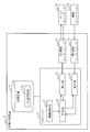
- FIG. 1 is a configuration diagram of a position specifying device 10 according to a first embodiment. Explanatory drawing of the position memory
- FIG. 4 is a process flow diagram of position specifying processing according to the first embodiment.
- 5 is a flowchart of relevant value identification processing according to the first embodiment. The figure which shows the illumination intensity detected by each illumination intensity sensor which concerns on Embodiment 1.
- FIG. The figure which shows the change of the record of the position memory
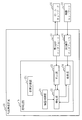
- FIG. FIG. 3 is a configuration diagram of a network system 100 according to a second embodiment.
- FIG. 10 is a process flowchart of position specifying processing according to the second embodiment.
- FIG. 4 is a configuration diagram of a network system 100 according to a third embodiment.
- FIG. 6 is a configuration diagram of a position specifying device 10 according to a third embodiment.
- FIG. 10 is a process flowchart of position specifying processing according to the third embodiment.
- FIG. 10 is a process flowchart of control processing according to Embodiment 4;
- FIG. 10 is a process flowchart of control processing according to Embodiment 5;
- Embodiment 1 FIG.
- the position specifying device 10 controls the device 50 under the control of the management device 40, and the device 50 is determined from the position information of the detection device managed by the position specifying device 10 and the detection value of the detection device. Identify the installed area.
- the network system 100 includes a home network 31 and device networks 32 and 33.
- the home network 31 includes a home router 41 installed in the residence 101.
- the home network 31 is configured using a wireless LAN (Local Area Network) or a wired LAN.
- the home network 31 is connected to the Internet 42 via a home router 41.
- the home network 31 is connected to the position specifying device 10 and the management device 40.
- the location specifying device 10 and the management device 40 perform IP (Internet Protocol) communication.
- the position specifying device 10 and the management device 40 are management devices of the M2M system and are computers.
- the device network 32 is configured by the position specifying device 10.
- the device network 32 is configured using a communication medium such as extra-low power radio.
- a home appliance 51 that is a device 50 installed in the residence 100, a housing facility 52, and a sensor 53 are connected.
- the device network 33 is configured by the management device 40.
- the device network 33 is configured using a communication medium such as extra-low power radio.
- a home appliance 54 that is a device 50 installed in the residence 100, a housing facility 55, and a sensor 56 are connected.
- the device networks 32 and 33 are not limited to extra-low power wireless, and may be configured by other communication media such as Bluetooth (registered trademark), wireless LAN, and wired LAN.
- the position specifying device 10 includes hardware of a processor 11, a storage device 12, a first communication interface 13, and a second communication interface 14.
- the processor 11 is connected to other hardware via a signal line, and controls these other hardware.
- the processor 11 is an IC (Integrated Circuit) that performs processing. Specific examples of the processor 11 are a CPU (Central Processing Unit), a DSP (Digital Signal Processor), and a GPU (Graphics Processing Unit).
- a CPU Central Processing Unit
- DSP Digital Signal Processor
- GPU Graphics Processing Unit
- the storage device 12 is, as a specific example, a RAM (Random Access Memory) or an HDD (Hard Disk Drive).
- the storage device 12 may be an SD (Secure Digital) memory card, CF (CompactFlash), NAND (Not AND) flash, flexible disk, optical disk, compact disk, Blu-ray (registered trademark) disk, DVD (Digital Versatile Disk), or the like. It may be a portable storage medium.
- the first communication interface 13 is a device for connecting to the home network 31.
- the first communication interface 13 is a NIC (Network Interface Card).
- the second communication interface 14 is a device for connecting to the device network 32.
- the second communication interface 14 is a NIC as a specific example.
- the position specifying device 10 includes a device control unit 21, a specifying unit 22, an instruction unit 23, and an acquisition unit 24 as functional components. Functions of the device control unit 21, the specifying unit 22, the instruction unit 23, and the acquisition unit 24 are realized by software.
- the storage device 12 stores a program that realizes the functions of the respective units of the position specifying device 10. This program is read by the processor 11 and executed by the processor 11. Thereby, the function of each part of position specifying device 10 is realized. Further, the storage device 12 implements a position storage unit 121.
- Information, data, signal values, and variable values indicating the processing results of the functions of the respective units realized by the processor 11 are stored in the storage device 12 or in a register or cache memory in the processor 11. In the following description, it is assumed that information, data, signal values, and variable values indicating the processing results of the functions of the respective units realized by the processor 11 are stored in the storage device 12.
- a program for realizing each function realized by the processor 11 is stored in the storage device 12.
- this program may be stored in a portable storage medium such as a magnetic disk, a flexible disk, an optical disk, a compact disk, a Blu-ray (registered trademark) disk, or a DVD.
- FIG. 2 only one processor 11 is shown. However, a plurality of processors 11 may be provided, and a plurality of processors 11 may execute programs that realize each function in cooperation with each other.
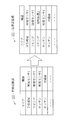
- the position storage unit 121 stores a name, which is first identification information indicating an installed area, as position information indicating an installation position for each device 50.
- the area indicates a range of granularity such as a room or a floor where the device 50 is installed.
- FIG. 3 shows that the refrigerator is installed in the area assigned the name “kitchen” and the illumination sensor 2 is installed in the area assigned the name “living room”.
- the position storage unit 121 stores at least an area for the device 50 connected to the device network 32 under the control of the position specifying device 10 as an initial state. In the position storage unit 121, an area for the device 50 connected to the device network 33 under the control of the management device 40 is added by a position specifying process described later.
- the operation of the position specifying device 10 according to the first embodiment corresponds to the position specifying method according to the first embodiment. Further, the operation of the position specifying device 10 according to the first embodiment corresponds to the processing of the position specifying program according to the first embodiment.
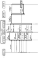
- the position specifying process according to the first embodiment will be described with reference to FIG. In FIG. 4, as a specific example, a processing sequence in a case where an area where the lighting device 1 under the control of the management device 40 is installed is specified.
- step S11 an instruction is transmitted from the device control unit 21 to the specifying unit 22, and the specifying unit 22 receives the instruction, thereby starting the position specifying process.
- the device control unit 21 has a function of controlling the device 50 and providing a service such as HEMS.
- the specifying unit 22 activates the acquisition unit 24 and transmits the identifier and control content of the device 50 to be controlled. Then, the acquisition unit 24 starts to acquire a plurality of detection values from the plurality of detection devices according to the type of control target device 50 indicated by the transmitted identifier and the control content via the second communication interface 14. In the example of FIG. 4, the specifying unit 22 transmits the identifier of the lighting device 1 that is the device 50 to be controlled and the lighting that is the control content to the instruction unit 23. Then, the acquisition unit 24 determines the illumination sensors 1, 2,... . . Start to get the detected value from.
- the specifying unit 22 activates the instruction unit 23 and transmits the identifier and control content of the device 50 to be controlled. Then, the instruction unit 23 transmits a control instruction for instructing to control the control target device 50 indicated by the transmitted identifier to the management apparatus 40 via the first communication interface 13. .
- the specifying unit 22 transmits the identifier of the lighting device 1 that is the device 50 to be controlled and the lighting that is the control content to the instruction unit 23. Then, the instruction unit 23 transmits a control instruction indicating that the lighting device 1 is lit to the management device 40.
- the management apparatus 40 controls the device 50 according to the control instruction. In the example of FIG. 4, the management device 40 performs control to turn on the lighting device 1.
- the management device 40 transmits a completion notification to the instruction unit 23.
- the instruction unit 23 receives the completion notification via the first communication interface 13
- the instruction unit 23 transmits the completion notification to the specifying unit 22.
- the specifying unit 22 transmits a detection value acquisition stop instruction to the acquisition unit 24.
- the acquisition unit 24 stops acquiring the detection value. Then, the acquisition unit 24 transmits a plurality of detection values acquired repeatedly from each detection device to the specifying unit 22.
- the specifying unit 22 specifies the corresponding value whose value has changed to a reference value or more from the plurality of detection values transmitted in step S14. And the specific
- step S16 the specifying unit 22 writes a record indicating the area specified in step S15 as the area where the control target device 50 is installed in the position storage unit 121.
- step S151 the specifying unit 22 receives a plurality of detection values acquired from each detection device transmitted in step S14.
- the specifying unit 22 executes processing of loop 1.
- the processing of loop 1 is executed in order for each detection device that is the detection source of the detection value received in step S151.
- the process of loop 1 is exited in step S154.
- step S152 the specifying unit 22 searches for the maximum value among the detection values detected by the detection device to which the index i is assigned.
- step S153 the specifying unit 22 searches for the minimum value among the detection values detected by the detection device for the index i.
- step S154 the specifying unit 22 determines whether or not the difference between the maximum value searched in step S152 and the minimum value searched in step S153 is greater than or equal to a reference value. If the difference is greater than or equal to the reference value, the specifying unit 22 exits the process of loop 1 and advances the process to step S155. On the other hand, when the difference is less than the reference value, the specifying unit 22 continues the process of loop 1.
- step S155 the specifying unit 22 specifies the area where the detection device to which the index i assigned when the difference is determined to be greater than or equal to the reference value in step S154 is present as the area where the control target device 50 is installed. .
- step S156 the identification unit 22 makes the area unidentifiable because the difference is less than the reference value for the detection devices to which all the indexes i are assigned.
- step S ⁇ b> 15 the specifying unit 22 executes the processing of loop 1 in order from the illuminance sensor 1. Then, for the illuminance sensor 1, the maximum value is retrieved as 15 (lx) in step S152 and the minimum value as 13 (lx) in step S153, and the difference is 2 (lx). Therefore, the difference is determined to be less than the reference value in step S154, and loop 1 is continued.
- step S152 the maximum value is retrieved as 300 (lx) in step S152 and the minimum value as 10 (lx) in step S153, and the difference is 290 (lx). Therefore, it is determined in step S154 that the difference is greater than or equal to the reference value, and in step S155, the area where the illuminance sensor 2 exists is specified as the area where the illumination device 1 is installed.
- the specifying unit 22 writes a record indicating living as an area where the illuminance sensor 1 is installed in the position storage unit 121, and the position storage unit 121 stores the table on the right side of FIG. .
- the lighting device has been described as a specific example of the device 50 to be controlled. Therefore, an illuminance sensor is used as the detection device.
- the device 50 to be controlled is not limited to the lighting device, but may be other types such as an air conditioner, a refrigerator, a washing machine, and a water heater.
- a detection apparatus is determined according to the kind and control content of the apparatus 50 as above-mentioned.
- a temperature sensor is used as a detection device when a temperature change occurs as in the case of cooling or heating the air conditioner.
- a sound sensor such as a microphone is used as a detection device.
- the detection device is attached to an illuminance sensor, a sound sensor, a temperature sensor, a humidity sensor, a wind speed sensor, an electric energy sensor, a current value sensor, a home appliance, and a residential equipment, depending on the type of device 50 and the control content.
- a device such as a sensor device can be used.
- the detected values are values such as illuminance, volume, temperature, humidity, wind speed, electric energy, and current value.
- the acquisition unit 24 acquires the detection value from the sensor 53 via the second communication interface 14.
- the acquisition unit 24 may acquire the detection value not only from the sensor 53 but also from the sensor 56 under the control of the management device 40 via the first communication interface 13.
- the position information needs to be stored in the position storage unit 121 for the sensor 56 from which the detection value is acquired.
- Embodiment 1 *** Effects of Embodiment 1 *** As described above, when the position specifying device 10 according to the first embodiment controls the device 50 under the control of the management device 40, the area in which the detection device that detects the detected value that has changed is present. It is specified that the device 50 is installed. Thereby, it is possible to specify the area where the device 50 under the control of the management apparatus 40 is installed with a simple configuration without providing a separate device.
- the area is specified using all the detected values transmitted in step S14.
- the transmission time at which the instruction unit 23 has transmitted the control instruction and the reception time at which the instruction unit 23 has received the completion notification are stored and detected between the transmission time and the reception time. Only the detection value may be used. That is, among the plurality of detection values acquired by the acquisition unit 24 between the time when the control instruction is transmitted by the instruction unit 23 and the time when the completion notification is received, the corresponding value whose value has changed to the reference value or more is obtained. It may be specified. As a result, the area is not identified using unnecessary detection values, and the identification accuracy is increased.
- ⁇ Modification 2> an instruction is transmitted from the device control unit 21 to the specifying unit 22, and the specifying unit 22 receives the instruction, whereby the position specifying process is started.
- the position specifying process may be started at another timing such as the timing when the management device 40 is controlled by the user or the timing when the device 50 or the new management device 40 is introduced.
- the position specifying device 10 includes a processing circuit 15 instead of the processor 11 and the storage device 12.
- the processing circuit 15 is a dedicated electronic circuit that realizes the functions of the respective units of the position specifying device 10 and the functions of the storage device 12.
- the processing circuit 15 is assumed to be a single circuit, a composite circuit, a programmed processor, a parallel programmed processor, a logic IC, a GA (Gate Array), an ASIC (Application Specific Integrated Circuit), or an FPGA (Field-Programmable Gate Array). Is done.
- the function of each part may be realized by one processing circuit 15, or the function of each part may be realized by being distributed to a plurality of processing circuits 15.
- ⁇ Modification 4> As a fourth modification, some functions may be realized by hardware, and other functions may be realized by software. That is, some of the functions of the position specifying device 10 may be realized by hardware, and other functions may be realized by software.
- the processor 11, the storage device 12, and the processing circuit 15 are collectively referred to as “processing circuitries”. That is, the function of each part is realized by a processing circuit.
- Embodiment 2 uses the correspondence information between the first identification information, which is the name assigned to the area in the position specifying device 10, and the second identification information, which is the name assigned to the area in the management device 40.
- the point which specifies the area where 50 is installed differs from Embodiment 1.
- the network system 100 is different from the network system 100 shown in FIG. 1 in that a location storage unit 401 is provided in the management apparatus 40.
- the position storage unit 401 stores, for each device 50, a name that is second identification information indicating an installed area as position information indicating an installation position.
- the position storage unit 401 stores at least an area for the device 50 connected to the device network 33 under the control of the management device 40.
- the location specifying device 10 can acquire information stored in the location storage unit 401 from the management device 40 via the communication API.
- the position specifying device 10 differs from the position specifying device 10 shown in FIG. 2 in that the storage device 12 implements the correspondence storage unit 122.
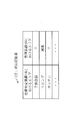
- the correspondence storage unit 122 stores correspondence information indicating a correspondence relationship between the name assigned as the first identification information in the position specifying device 10 and the name assigned as the second identification information in the management device 40.
- the correspondence storage unit 122 stores correspondence information between the names assigned by the position specifying device 10 and the names assigned by each management device 40.
- “living room” in the position specifying device 10 corresponds to “living room” in the management device 40.
- the operation of the position specifying device 10 according to the second embodiment corresponds to the position specifying method according to the second embodiment.
- the operation of the position specifying device 10 according to the second embodiment corresponds to the processing of the position specifying program according to the second embodiment.
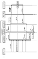
- FIG. 12 the position specifying process according to the second embodiment will be described.
- a processing sequence in a case where an area where the lighting device 2 under the control of the management device 40 is installed is specified.
- step S21 is the same as the process of step S11 of FIG.
- the specifying unit 22 activates the instruction unit 23 and transmits the identifier of the device 50 to be controlled. Then, the instruction unit 23 transmits an acquisition request for the area where the control target device 50 indicated by the transmitted identifier is installed to the management device 40.
- the specifying unit 22 transmits the identifier of the lighting device 2 that is the device 50 to be controlled to the instruction unit 23. Then, the instruction unit 23 transmits an acquisition request for the area of the lighting device 2 to the management device 40.
- the management device 40 When the management device 40 receives the acquisition request, the management device 40 acquires a name indicating the area where the device 50 is installed from the position storage unit 401 according to the acquisition request and transmits the name to the instruction unit 23.
- the name transmitted here is a name in the management device 40. In the example of FIG. 12, it is assumed that “living room” is transmitted to the instruction unit 23 as a name indicating an area where the lighting device 2 is installed.
- the instruction unit 23 receives a name via the first communication interface 13, the instruction unit 23 transmits the name to the specifying unit 22.
- the identifying unit 22 acquires the name in the position identifying device 10 corresponding to the name transmitted from the instruction unit 23 in step S22 from the correspondence storage unit 122.
- the specifying unit 22 specifies the area indicated by the acquired name as the area where the device 50 to be controlled is installed. That is, the specifying unit 22 acquires the name that is the second identification information of the area in which the device 50 is installed from the management device 40, and the name that is the acquired second identification information is stored in the correspondence storage unit 122. It converts into the name which is 1st identification information by correspondence information, and specifies the area which the name which is the converted 1st identification information shows as an area in which the apparatus 50 was installed.
- specification part 22 writes the record which shows the specified area as the area where the apparatus 50 of control object was installed in the position memory
- the specifying unit 22 specifies the area where the control target device 50 is installed by the process shown in FIG. 4 described in the first embodiment.
- the specifying unit 22 corresponds to the “living room” that is the name in the management device 40 transmitted in step S22, and the correspondence storage unit illustrated in FIG. 122. And the specific
- the specifying unit 22 cannot acquire the name in the position specifying device 10 in step S23, and if the area is specified by the process shown in FIG. 4 described in the first embodiment, the name of the specified area,
- the name transmitted in step S22 may be associated with and written in the correspondence storage unit 122. That is, the specifying unit 22 may write the name of the specified area as the name in the position specifying device 10 and the name transmitted in step S22 as the name in the management device 40 and write it in the correspondence storage unit 122. Thereby, after that, when the same name is transmitted in step S22, the specifying unit 22 can acquire the name in the position specifying device 10 in step S23.
- the position specifying device 10 specifies the area in which the device 50 is installed using the correspondence information between the first identification information and the second identification information. Thereby, when the first identification information and the second identification information are associated with each other, the area can be specified without operating the device 50. Further, there is a possibility that the area can be specified even when the area cannot be specified by the process shown in FIG. 4 described in the first embodiment.
- Embodiment 3 FIG.
- the third embodiment is different from the first and second embodiments in that the position can be detected and the mobile terminal 43 that acquires sound data is used as a detection device. In the third embodiment, this different point will be described. In the third embodiment, differences from the first embodiment will be described.
- the network system 100 is different from the network system 100 shown in FIG. 1 in that one or more portable terminals 43 are connected to the home network 31.
- the mobile terminal 43 can detect the position in the building by any method such as a method using the radio field intensity of WiFi, a method using Bluetooth (registered trademark) Beacon, or a method using sound waves.
- the mobile terminal 43 includes a device that acquires sound data such as a microphone.
- the portable terminal 43 is a terminal such as a smartphone, a cellular phone, or a portable PC (Personal Computer).
- the instruction unit 23 receives information transmitted from the mobile terminal 43 via the first communication interface 13, and the acquisition unit 24 is connected to the first communication interface 13. It differs from the position specifying device 10 shown in FIG.
- the operation of the position specifying device 10 according to the third embodiment corresponds to the position specifying method according to the third embodiment.
- the operation of the position specifying device 10 according to the third embodiment corresponds to the processing of the position specifying program according to the third embodiment.
- the position specifying process according to the third embodiment will be described with reference to FIG. In FIG. 15, as a specific example, a processing sequence in a case where an area where an air conditioner under the control of the management device 40 is installed is specified.
- step S31 is the same as the process of step S11 of FIG.
- step S ⁇ b> 32 the specifying unit 22 activates the acquisition unit 24. Then, the acquisition unit 24 transmits an acquisition start instruction to the plurality of mobile terminals 43, and sets a plurality of sets of sound data and position data as detection values from the plurality of mobile terminals 43 via the first communication interface 13. And start getting.
- the acquisition unit 24 includes the mobile terminals 43 ⁇ / b> A, 43 ⁇ / b> B,. . . To start acquiring a plurality of sets of sound data and position data as detection values.
- step S33 is the same as the process of step S13 of FIG.
- the specifying unit 22 transmits the identifier of the air conditioner that is the device 50 to be controlled and the activation that is the control content to the instruction unit 23.
- indication part 23 transmits the control instruction
- FIG. The management device 40 performs control to activate the air conditioner.
- the management device 40 transmits a completion notification to the instruction unit 23.
- the instruction unit 23 receives the completion notification via the first communication interface 13, the instruction unit 23 transmits the completion notification to the specifying unit 22.
- the identification unit 22 transmits a set acquisition stop instruction to the acquisition unit 24 when receiving the completion notification.
- the acquisition unit 24 transmits an acquisition stop instruction to the plurality of mobile terminals 43 and stops acquiring the set. Then, the acquisition unit 24 transmits a plurality of sets acquired from each mobile terminal 43 to the specifying unit 22.
- the specifying unit 22 specifies the corresponding value in which the volume of the sound data that is the detection value included in the plurality of sets transmitted in step S34 has changed to a reference value or more.
- specification part 22 specifies the area containing the position which the position data contained in the same set as the sound data which is the specified applicable value shows as an area where the apparatus 50 was installed.
- the specifying unit 22 includes the mobile terminals 43A, 43B,. . . It is sequentially determined whether or not the volume of the sound data acquired by each has changed to a reference value or more.
- the specifying unit 22 specifies the area including the position indicated by the position data included in the same set as the sound data as the area where the air conditioner is installed. To do.
- the fact that the volume of the sound data has changed is used here, the fact that the sound quality such as the pitch of the sound is changed is not limited to the volume.
- step S36 the specifying unit 22 writes a record indicating the area specified in step S35 as the area where the device 50 to be controlled is installed in the position storage unit 121.
- the position specifying device 10 can detect the position, and uses the mobile terminal 43 that acquires sound data as the detection device. Thereby, even if there is no detection device in which the installed area is specified, the area where the device 50 under the control of the management device 40 is installed can be specified by arranging the mobile terminal 43. Is possible.
- the acquisition unit 24 acquires the detection value only from the mobile terminal 43.
- the detection value may be acquired from the mobile terminal 43 and the detection value may be acquired from another detection device as in the first embodiment. Thereby, in addition to the detection device in which the installed area is specified, it is possible to specify the area in which the device 50 is installed using the mobile terminal 43 as the detection device.
- Embodiment 4 FIG. In the first to third embodiments, the method of specifying the area where the device 50 under the control of the management apparatus 40 is installed has been described.
- the fourth embodiment is different from the first to third embodiments in that when the device 50 in which the already installed area is specified is controlled, it is specified that the device 50 is controlled according to the control instruction. In the fourth embodiment, this different point will be described. In the fourth embodiment, differences from the first embodiment will be described.
- the management device 40 transmits a completion notification when the control is completed. Thereby, the position specifying device 10 was able to confirm that the control by the management device 40 was performed. However, depending on the management device 40, a completion notification may not be transmitted. In the fourth embodiment, whether or not the control by the management device 40 is performed even when the completion notification is not performed from the management device 40 is specified.
- the operation of the position specifying device 10 according to the fourth embodiment corresponds to the position specifying method according to the fourth embodiment.
- the operation of the position specifying device 10 according to the fourth embodiment corresponds to the processing of the position specifying program according to the fourth embodiment.
- FIG. 16 shows a processing sequence when the lighting device 1 under the control of the management device 40 is turned on as a specific example.
- the illuminance sensor 2 is installed in the same area as the lighting device 1.
- step S41 an instruction is transmitted from the device control unit 21 to the specifying unit 22, and the specifying unit 22 receives the instruction, thereby starting the control process.
- the identification unit 22 activates the acquisition unit 24 and is installed in the same area as the device 50 to be controlled, and the detection device according to the type and control content of the device 50 to be controlled. Send identifier. Then, the acquisition unit 24 starts acquiring the detection value from the detection device indicated by the transmitted identifier via the second communication interface 14.
- the specifying unit 22 is installed in the same area as the lighting device 1 that is the device 50 to be controlled, and the illuminance sensor 2 according to the lighting device that is the type of the device 50 and lighting that is the control content. Is transmitted to the instruction unit 23. Then, the acquisition unit 24 starts to acquire a detection value from the illuminance sensor 2.
- the specifying unit 22 activates the instruction unit 23, and transmits the identifier and control content of the device 50 to be controlled. Then, the instruction unit 23 transmits a control instruction for instructing to control the control target device 50 indicated by the transmitted identifier to the management apparatus 40 via the first communication interface 13. .
- the specifying unit 22 transmits the identifier of the lighting device 1 that is the device 50 to be controlled and the lighting that is the control content to the instruction unit 23. Then, the instruction unit 23 transmits a control instruction indicating that the lighting device 1 is lit to the management device 40.
- the management apparatus 40 When the management apparatus 40 receives the control instruction, the management apparatus 40 controls the device 50 according to the control instruction. In the example of FIG. 16, the management device 40 performs control to turn on the lighting device 1. However, the management device 40 does not transmit a completion notification to the instruction unit 23 even when the control is completed.
- step S44 the instruction unit 23 transmits a control completion inquiry to the specifying unit 22.
- the specifying unit 22 transmits a detection value acquisition request to the acquisition unit 24. Then, the acquisition unit 24 transmits the acquired detection value to the specifying unit 22.
- the specifying unit 22 notifies the instruction unit 23 of the result determined in step S46.
- the identifying unit 22 also notifies the device control unit 21 of the result determined in step S46.
- the specifying unit 22 may notify the result to the user or the system administrator by a method of displaying the result determined in step S46 on the display device.
- Embodiment 5 FIG.
- the fifth embodiment is different from the first to fourth embodiments in that an abnormality of the device 50 is specified when the device 50 in which an already installed area is specified is controlled. In the fifth embodiment, this different point will be described. In the fifth embodiment, differences from the fourth embodiment will be described.
- the operation of the position specifying device 10 according to the fourth embodiment corresponds to the position specifying method according to the fifth embodiment. Further, the operation of the position specifying device 10 according to the fifth embodiment corresponds to the processing of the position specifying program according to the fifth embodiment.
- FIG. 17 A control process according to the fifth embodiment will be described with reference to FIG. 17, as a specific example, similarly to the example of FIG. 16, a processing sequence in the case of lighting the lighting device 1 under the control of the management device 40 is shown. In FIG. 17, it is assumed that the illuminance sensor 2 is installed in the same area as the lighting device 1.
- step S53 the management device 40 transmits a completion notification to the instruction unit 23 when the control is completed.
- the instruction unit 23 receives the completion notification via the first communication interface 13
- the instruction unit 23 transmits the completion notification to the specifying unit 22.
- the identification unit 22 transmits a detection value acquisition stop instruction to the acquisition unit 24 upon receiving the completion notification.
- the acquisition unit 24 stops acquiring the detection value. Then, the acquisition unit 24 transmits the detection value acquired from each detection device to the specifying unit 22.
- the specifying unit 22 analyzes the detection value transmitted in step S54 and determines whether or not the detection value has changed to a reference value or more.
- the specifying unit 22 determines that the detection value is normal when the detection value changes to a reference value or more.
- the specifying unit 22 determines that the detected value is abnormal, and notifies the user or the system administrator of the abnormality by a method of displaying on the display device.
- the specifying unit 22 may notify the device control unit 21 of the abnormality.
- the control target device 50 depends on whether or not the detection value detected by the detection device installed in the same area as the control target device 50 has changed. It is determined whether or not is operating normally. Thereby, even when the abnormality is not notified from the management device 40, the abnormality of the device 50 can be specified. Some management devices 40 notify the abnormality of the device 50 together with the completion notification. However, the abnormality of the device 50 can be specified also when the management device 40 does not notify the abnormality and when the management device 40 does not detect the abnormality. For example, although the device 50 is operating, an abnormal state before a complete failure can be identified, such as when an operation state that is different from the normal state due to deterioration over time or when an abnormal noise occurs. .
- the user or the system administrator can replace the device 50 or repair the device 50 before the device 50 completely fails and does not operate.
Landscapes
- Engineering & Computer Science (AREA)
- Power Engineering (AREA)
- Remote Monitoring And Control Of Power-Distribution Networks (AREA)
- Selective Calling Equipment (AREA)
Abstract
L'invention concerne un dispositif de spécification d'emplacement (10) qui envoie, à un dispositif de gestion (40) qui gère un appareil (50), des instructions de commande relatives à l'appareil (50) et acquiert de manière répétée une pluralité de valeurs de détection détectées par une pluralité de capteurs (53, 56). Le dispositif de spécification d'emplacement (10) spécifie une valeur de détection qui a varié d'au moins une valeur de référence parmi une pluralité de valeurs de détection ainsi acquises, et spécifie, comme zone dans laquelle l'appareil (50) est disposé, une zone dans laquelle les capteurs (53, 56) qui ont détecté la valeur spécifiée sont présents.
Priority Applications (2)
| Application Number | Priority Date | Filing Date | Title |
|---|---|---|---|
| PCT/JP2016/054771 WO2017141409A1 (fr) | 2016-02-19 | 2016-02-19 | Dispositif de spécification d'emplacement, procédé de spécification d'emplacement et programme de spécification d'emplacement |
| JP2017549435A JP6250251B1 (ja) | 2016-02-19 | 2016-02-19 | 位置特定装置、位置特定方法及び位置特定プログラム |
Applications Claiming Priority (1)
| Application Number | Priority Date | Filing Date | Title |
|---|---|---|---|
| PCT/JP2016/054771 WO2017141409A1 (fr) | 2016-02-19 | 2016-02-19 | Dispositif de spécification d'emplacement, procédé de spécification d'emplacement et programme de spécification d'emplacement |
Publications (1)
| Publication Number | Publication Date |
|---|---|
| WO2017141409A1 true WO2017141409A1 (fr) | 2017-08-24 |
Family
ID=59625742
Family Applications (1)
| Application Number | Title | Priority Date | Filing Date |
|---|---|---|---|
| PCT/JP2016/054771 Ceased WO2017141409A1 (fr) | 2016-02-19 | 2016-02-19 | Dispositif de spécification d'emplacement, procédé de spécification d'emplacement et programme de spécification d'emplacement |
Country Status (2)
| Country | Link |
|---|---|
| JP (1) | JP6250251B1 (fr) |
| WO (1) | WO2017141409A1 (fr) |
Citations (2)
| Publication number | Priority date | Publication date | Assignee | Title |
|---|---|---|---|---|
| JPH11301942A (ja) * | 1998-04-24 | 1999-11-02 | Otis Elevator Co | エレベーターの遠隔点検装置 |
| JP2010508803A (ja) * | 2006-10-27 | 2010-03-18 | マニフォールド・プロダクツ・エルエルシー | 配線網をマッピングするための装置及び方法 |
-
2016
- 2016-02-19 WO PCT/JP2016/054771 patent/WO2017141409A1/fr not_active Ceased
- 2016-02-19 JP JP2017549435A patent/JP6250251B1/ja not_active Expired - Fee Related
Patent Citations (2)
| Publication number | Priority date | Publication date | Assignee | Title |
|---|---|---|---|---|
| JPH11301942A (ja) * | 1998-04-24 | 1999-11-02 | Otis Elevator Co | エレベーターの遠隔点検装置 |
| JP2010508803A (ja) * | 2006-10-27 | 2010-03-18 | マニフォールド・プロダクツ・エルエルシー | 配線網をマッピングするための装置及び方法 |
Also Published As
| Publication number | Publication date |
|---|---|
| JPWO2017141409A1 (ja) | 2018-02-22 |
| JP6250251B1 (ja) | 2017-12-20 |
Similar Documents
| Publication | Publication Date | Title |
|---|---|---|
| US11221598B2 (en) | Method and apparatus for controlling device using a service rule | |
| EP3235182B1 (fr) | Procédé et appareil pour commander un dispositif à l'aide d'une règle de service | |
| JP6392788B2 (ja) | IoTデバイス用の解析エンジン | |
| JP6868038B2 (ja) | 物理的環境を監視及び制御するためのクラウドベースのシステムにおけるシステムデバイスを更新するためのシステム及び方法 | |
| ES2823226T3 (es) | Método, aparato y sistema de control | |
| US20160073482A1 (en) | Implementing a target lighting scene in an internet of things environment using a mobile light output device | |
| US20220039245A1 (en) | Systems and methods for sensic device localization | |
| US20160234213A1 (en) | Apparatus and method by which user device in home network system transmits home-device-related information | |
| US11388597B2 (en) | Systems and methods for authenticating wireless modules | |
| JP2019522251A (ja) | 物理的環境を監視するためのコンピューティングクラウド | |
| US20160149716A1 (en) | Remote Management And Control Of Utility Appliances | |
| KR20150121128A (ko) | Iot 디바이스를 위한 긴급 모드 | |
| WO2016205213A1 (fr) | Systèmes et procédés destinés à l'automatisation domotique à l'aide d'un état multifonction et d'une icône de point d'entrée | |
| KR20160084585A (ko) | 센서 정보 처리 방법 및 장치 | |
| JP6665660B2 (ja) | 機器制御システム、及び機器制御方法 | |
| US10989426B2 (en) | Information processing device, electronic apparatus, method, and program | |
| CN110913356A (zh) | 物联网(IoT)服务器和包括其的IoT系统 | |
| US12506637B2 (en) | Building management system with multi-interface gateway | |
| CN112068510A (zh) | 智能设备的控制方法、装置、电子设备及计算机存储介质 | |
| JP6250251B1 (ja) | 位置特定装置、位置特定方法及び位置特定プログラム | |
| EP4158921A1 (fr) | Exécution d'une commande de contrôle en fonction de la détection d'une présence | |
| CN114616927A (zh) | 在将所述桥接器添加到照明系统之后配置具有组的桥接器 | |
| US11075775B2 (en) | Home automation system including cloud server based maintenance operation communication and related methods | |
| KR20200070175A (ko) | 호스트 및 클라이언트의 타겟 디바이스에 대한 제어방법 및 장치 | |
| US10331155B1 (en) | Network addressable power socket automation |
Legal Events
| Date | Code | Title | Description |
|---|---|---|---|
| ENP | Entry into the national phase |
Ref document number: 2017549435 Country of ref document: JP Kind code of ref document: A |
|
| 121 | Ep: the epo has been informed by wipo that ep was designated in this application |
Ref document number: 16890550 Country of ref document: EP Kind code of ref document: A1 |
|
| NENP | Non-entry into the national phase |
Ref country code: DE |
|
| 122 | Ep: pct application non-entry in european phase |
Ref document number: 16890550 Country of ref document: EP Kind code of ref document: A1 |