WO2017141460A1 - 圧力センサ - Google Patents
圧力センサ Download PDFInfo
- Publication number
- WO2017141460A1 WO2017141460A1 PCT/JP2016/068670 JP2016068670W WO2017141460A1 WO 2017141460 A1 WO2017141460 A1 WO 2017141460A1 JP 2016068670 W JP2016068670 W JP 2016068670W WO 2017141460 A1 WO2017141460 A1 WO 2017141460A1
- Authority
- WO
- WIPO (PCT)
- Prior art keywords
- case
- convex portion
- end surface
- pressure sensor
- piezoelectric element
- Prior art date
- Legal status (The legal status is an assumption and is not a legal conclusion. Google has not performed a legal analysis and makes no representation as to the accuracy of the status listed.)
- Ceased
Links
Images





Classifications
-
- G—PHYSICS
- G01—MEASURING; TESTING
- G01L—MEASURING FORCE, STRESS, TORQUE, WORK, MECHANICAL POWER, MECHANICAL EFFICIENCY, OR FLUID PRESSURE
- G01L9/00—Measuring steady of quasi-steady pressure of fluid or fluent solid material by electric or magnetic pressure-sensitive elements; Transmitting or indicating the displacement of mechanical pressure-sensitive elements, used to measure the steady or quasi-steady pressure of a fluid or fluent solid material, by electric or magnetic means
- G01L9/0041—Transmitting or indicating the displacement of flexible diaphragms
- G01L9/008—Transmitting or indicating the displacement of flexible diaphragms using piezoelectric devices
-
- G—PHYSICS
- G01—MEASURING; TESTING
- G01L—MEASURING FORCE, STRESS, TORQUE, WORK, MECHANICAL POWER, MECHANICAL EFFICIENCY, OR FLUID PRESSURE
- G01L1/00—Measuring force or stress, in general
- G01L1/16—Measuring force or stress, in general using properties of piezoelectric devices
-
- G—PHYSICS
- G01—MEASURING; TESTING
- G01L—MEASURING FORCE, STRESS, TORQUE, WORK, MECHANICAL POWER, MECHANICAL EFFICIENCY, OR FLUID PRESSURE
- G01L9/00—Measuring steady of quasi-steady pressure of fluid or fluent solid material by electric or magnetic pressure-sensitive elements; Transmitting or indicating the displacement of mechanical pressure-sensitive elements, used to measure the steady or quasi-steady pressure of a fluid or fluent solid material, by electric or magnetic means
- G01L9/08—Measuring steady of quasi-steady pressure of fluid or fluent solid material by electric or magnetic pressure-sensitive elements; Transmitting or indicating the displacement of mechanical pressure-sensitive elements, used to measure the steady or quasi-steady pressure of a fluid or fluent solid material, by electric or magnetic means by making use of piezoelectric devices, i.e. electric circuits therefor
-
- H—ELECTRICITY
- H10—SEMICONDUCTOR DEVICES; ELECTRIC SOLID-STATE DEVICES NOT OTHERWISE PROVIDED FOR
- H10N—ELECTRIC SOLID-STATE DEVICES NOT OTHERWISE PROVIDED FOR
- H10N30/00—Piezoelectric or electrostrictive devices
- H10N30/30—Piezoelectric or electrostrictive devices with mechanical input and electrical output, e.g. functioning as generators or sensors
- H10N30/302—Sensors
-
- H—ELECTRICITY
- H10—SEMICONDUCTOR DEVICES; ELECTRIC SOLID-STATE DEVICES NOT OTHERWISE PROVIDED FOR
- H10N—ELECTRIC SOLID-STATE DEVICES NOT OTHERWISE PROVIDED FOR
- H10N30/00—Piezoelectric or electrostrictive devices
- H10N30/50—Piezoelectric or electrostrictive devices having a stacked or multilayer structure
-
- H—ELECTRICITY
- H10—SEMICONDUCTOR DEVICES; ELECTRIC SOLID-STATE DEVICES NOT OTHERWISE PROVIDED FOR
- H10N—ELECTRIC SOLID-STATE DEVICES NOT OTHERWISE PROVIDED FOR
- H10N30/00—Piezoelectric or electrostrictive devices
- H10N30/80—Constructional details
- H10N30/87—Electrodes or interconnections, e.g. leads or terminals
- H10N30/871—Single-layered electrodes of multilayer piezoelectric or electrostrictive devices, e.g. internal electrodes
-
- H—ELECTRICITY
- H10—SEMICONDUCTOR DEVICES; ELECTRIC SOLID-STATE DEVICES NOT OTHERWISE PROVIDED FOR
- H10N—ELECTRIC SOLID-STATE DEVICES NOT OTHERWISE PROVIDED FOR
- H10N30/00—Piezoelectric or electrostrictive devices
- H10N30/80—Constructional details
- H10N30/87—Electrodes or interconnections, e.g. leads or terminals
- H10N30/872—Interconnections, e.g. connection electrodes of multilayer piezoelectric or electrostrictive devices
-
- G—PHYSICS
- G01—MEASURING; TESTING
- G01L—MEASURING FORCE, STRESS, TORQUE, WORK, MECHANICAL POWER, MECHANICAL EFFICIENCY, OR FLUID PRESSURE
- G01L19/00—Details of, or accessories for, apparatus for measuring steady or quasi-steady pressure of a fluent medium insofar as such details or accessories are not special to particular types of pressure gauges
- G01L19/14—Housings
- G01L19/147—Details about the mounting of the sensor to support or covering means
Definitions
- the present disclosure relates to a pressure sensor using a multilayer piezoelectric element.
- a piezoelectric element housed in a case is used as a drive source or pressure sensor for a fuel injection device.
- a strong member such as a shaft is connected to the piezoelectric element to transmit a strong force to the outside.
- a pressure sensor in order to obtain a highly sensitive output by connecting a thin member, a piezoelectric element is placed in a thin case and the end face of the piezoelectric element is placed on the inner surface of the case. Was abutting.
- a shape has been devised in which the thickness of the case is increased by projecting a portion in contact with the piezoelectric element inward so that force is effectively transmitted between the outside and the piezoelectric element. (For example, refer to Patent Document 1 and Patent Document 2).
- the pressure sensor of the present disclosure includes a stacked piezoelectric element including a stacked body in which piezoelectric layers and internal electrodes are alternately stacked, and a case surrounding the stacked piezoelectric element, and the case includes a case body. And a first convex portion protruding inward from the case body, and an end surface of the first convex portion is in contact with an end surface in the stacking direction of the laminate, and an outer periphery of the end surface of the laminate It is characterized by being located on the inner side.
- FIG. 2 is a cross-sectional view showing a cross section (vertical cross section) taken along line ii-ii of the pressure sensor of FIG.
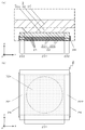
- A is sectional drawing which expands and shows the principal part (A part) of FIG. 2
- (b) is the top view which planarly viewed (a).
- (A) is sectional drawing which shows the principal part of the modification of a pressure sensor
- (b) is the top view which planarly viewed (a).
- FIG. 1 an orthogonal coordinate system xyz defined to be fixed to the pressure sensor 1 is attached.
- Any direction of the piezoelectric component 1 may be a vertical direction or a horizontal direction, and the z-axis direction may be referred to as a vertical direction, a height direction, or a thickness direction.
- the pressure sensor 1 is simply referred to as a plan view, it refers to viewing in the z-axis direction.
- this invention is not limited by embodiment shown below.
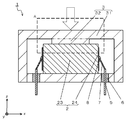
- the pressure sensor 1 of the present embodiment includes a stacked piezoelectric element 2 (hereinafter simply referred to as a piezoelectric device) including a stacked body 23 in which piezoelectric layers 21 and internal electrodes 22 are alternately stacked, as in the examples shown in FIGS. And a case 3 surrounding the multilayer piezoelectric element 2.
- the case 3 includes a case main body 31 and a first convex portion 32 protruding inward from the inner surface of the case main body 31.
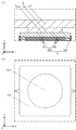
- the end surface 32 a of the first convex portion 32 is in contact with the end surface of the stacked body 23 in the stacking direction and is located on the inner side of the outer periphery of the end surface of the stacked body 23.
- the pressure sensor 1 When pressure is applied to the pressure sensor 1 as indicated by the white arrow shown in FIGS. 1 and 2, the pressure is applied to the piezoelectric element 2 through the case 3.
- the pressure sensor 1 outputs a voltage generated by applying pressure to the piezoelectric layer 21 of the piezoelectric element 2 to the outside.
- the magnitude of pressure is calculated from the magnitude of this voltage.
- the laminated piezoelectric element 2 is accommodated in the internal space of the cylindrical case 3.
- the piezoelectric element 2 is sandwiched and stored between the upper and lower walls of the case 3.
- the upper outer surface of the case 3 is a surface to which an external force is applied, and the end surface of the first convex portion 32 provided on the inner surface (the top surface of the internal space) of the case 3 facing the case 3 is in contact with the upper end surface of the piezoelectric element 2.
- the end surface of the first convex portion 32 is a surface that transmits an external force to the piezoelectric element 2.
- the piezoelectric element 2 is a stacked piezoelectric element 2 including a stacked body 23 in which piezoelectric layers 21 and internal electrodes 22 are alternately stacked, and has a first protrusion on one end surface (upper end surface) in the stacking direction of the stacked body 23.
- the end surface of the part 32 is in contact.
- the other end surface (lower end surface) of the stacked body 23 is in contact with an inner surface (a bottom surface of the internal space) facing the lower outer surface of the case 3.
- the pressure sensor 1 of the present embodiment includes a lead terminal 5 extending from the inside space of the case 3 to the outside.
- the lead terminal 5 is electrically connected to the piezoelectric element 2.
- the voltage generated in the piezoelectric element 2 is output to the outside through the lead terminal 5.
- the end surface 32a of the first convex portion 32 is located on the inner side of the outer periphery of the end surface (upper end surface) of the stacked body 23 as in the example shown in FIG.
- the thick portion of the case 3 (the end surface of the first convex portion 32) is larger or the same size as the end surface of the piezoelectric element 2.
- the force applied to the outer surface of the case 3 is concentrated in the vicinity of the outer edge, the corner between the end surface and the side surface. As a result, cracks are likely to occur in the piezoelectric element 2, and the sensitivity of the pressure sensor may gradually decrease as the cracks progress.
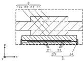
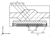
- the case 3 may have a second convex portion 33.
- the second convex portion 33 is provided so as to face the first convex portion 32 with the case main body 31 interposed therebetween, and projects outward from the outer surface of the case main body 31. Since the thickness of the portion of the case 3 that abuts against the piezoelectric element 2 is increased, when an external force is applied to the pressure sensor 1, the end surface 32a of the first convex portion 32 is deformed even if the case body 31 of the case 3 is deformed as a whole. The deformation is small and flatness is maintained.
- the end surface 32a of the first convex portion 32 does not come into contact with the end surface of the piezoelectric element 2 (laminated body 23), and stress is evenly applied to the end surface of the piezoelectric element 2, so that cracks are unlikely to occur.
- the length in the cross-sectional view of the boundary between the first convex portion 32 and the case main body 31 and the cross-sectional view in the boundary between the second convex portion 33 and the case main body 31 may be different.
- the cross section here is a cross section cut in the thickness direction of the first protrusion 32 and the second protrusion 33 and in the stacking direction of the stacked body 23.
- the boundary between the first protrusion 32 and the case body 31 and the boundary between the second protrusion 33 and the case body 31 are indicated by two-dot chain lines.
- the widths (root widths) of the end portions of the first convex portion 32 and the second convex portion 33 on the case body 31 side in the cross-sectional view may be different from each other.
- the outer periphery of the end portion of the first convex portion 32 on the case body 31 side does not overlap the outer periphery of the end portion of the second convex portion 33 on the case body 31 side.
- the outer periphery of the end portion of the first convex portion 32 on the case body 31 side may be shifted from the outer periphery of the end portion of the second convex portion 33 on the case main body 31 side by, for example, more than the thickness of the case main body 31.
- the first convex portion 31 is larger than the second convex portion 32, but the present invention is not limited to this and may be reversed. If the 2nd convex part 32 is smaller than the 1st convex part 31, the end surface of the 2nd convex part 32 which is a part which detects an external pressure will become small, and the pressure of a finer part can be detected.
- the first convex portion 32 is large on the case main body 31 side (the inner surface side of the case 3) from the end surface 32 a to the inner surface of the case main body 31.
- the side surface of the portion 32 may be inclined with respect to the inner surface of the case body 31. Since the angle of the corner portion between the end surface and the side surface of the first convex portion 32 becomes an obtuse angle, even if the corner portion hits the end surface of the piezoelectric element 2, stress concentration is reduced. Therefore, it is possible to reduce the possibility of cracks occurring in the laminate 23 starting from the portion where the corners hit and the stress is concentrated.
- the case main body 31 side increases from the end surface of the second convex portion 33 to the outer surface of the case main body 31 as in the examples shown in FIGS.
- the side surface of the second convex portion 33 may be inclined with respect to the outer surface of the case body 31.
- the angle between the end surface and the side surface of the first protrusion 32 and the angle between the side surface of the first protrusion 32 and the inner surface of the case main body 31 are set to, for example, 105 ° to 150 °.
- the corner between the end surface and the side surface of the first convex portion 32 may be rounded to form a curved surface. It is possible to further reduce the possibility of cracks occurring in the laminate 23 starting from a portion where stress is concentrated by hitting the corner.
- the corner between the side surface of the first protrusion 32 and the inner surface of the case body 31 may be rounded to be a curved surface. The possibility of cracks occurring in the case body 31 starting from the corners can be further reduced.
- Any of the configurations that are curved as described above have the same effect even when the side surface of the first convex portion 32 is not inclined.
- the resin 4 may be provided between the end surface (upper end surface) of the stacked body 23 with which the first convex portion 32 is in contact and the case body 31. More specifically, the resin 4 is provided around the first convex portion 32 on the end face (upper end face) of the laminate 23 of the piezoelectric element 2. Since the resin 4 is provided around the first convex portion 32, the position of the end surface 32 a of the first convex portion 32 moves even when the case 3 is greatly deformed due to a large external force applied to the pressure sensor 1. Is suppressed. Therefore, it is possible to prevent the end surface 32a of the first convex portion 32 from being obliquely applied to the end surface of the stacked body 23, and to reduce the possibility of cracks occurring in the stacked body 23.
- Resin 4 can be, for example, epoxy or phenolic. It may contain a filler such as ceramic particles.
- the resin 4 is provided in a region other than a region where the end surface 32 a of the first convex portion 32 abuts on the end surface of the laminate 23.
- the thickness is set to 0.01 mm to 0.5 mm, for example. By setting the thickness not to contact the inner surface (case body 31) around the first convex portion 32 of the case 3, the external force is transmitted from the end surface 32 a of the first convex portion 32 to the end surface of the multilayer body 23 of the piezoelectric element 2. .
- the resin 4 is made of the above-described material and the material of the case 3 is made of a metal such as stainless steel, which will be described later, the resin 4 is sufficiently soft compared to the case 3 and the outer edge portion of the end face of the laminate 23 has Since a large stress is not applied, the thickness may be such that the resin 4 is in contact with the inner surface around the first convex portion 32 of the case 3. Further, the resin 4 may be provided from the end surface to the side surface of the piezoelectric body 23.
- the internal electrode 22 includes a first pole 221 and a second pole 222.
- the stacked body 23 includes an active portion 231 in which the first pole 221 and the second pole 222 of the internal electrode 22 overlap in the stacking direction and an inactive portion 232 that does not overlap in the stacking direction.
- the end surface 32a of the 1st convex part 32 can be made into the structure which overlaps from the active part 231 to a part of inactive part 232 seeing from a lamination direction (plan view) like the example shown in FIG. . If it does in this way, the corner
- FIG. 1 Even when a stronger external force is applied to the pressure sensor 1, the position where the corner portion of the first convex portion 32 hits and becomes the starting point of the crack becomes the inactive portion 232. Since the progress direction of the crack is the direction of the side surface of the laminated body 23, the possibility that the crack progresses in the active portion 231 is reduced, and the possibility that the function of the piezoelectric element 2 is impaired is reduced. When the outer periphery of the end surface 32a of the first convex portion 32 overlaps with the inactive portion 231 over the entire circumference when viewed from the stacking direction, this effect becomes more reliable.
- the portion of the outer periphery of the end surface 32 a of the first convex portion 32 that is closest to the side surface of the laminate 23 (the outer periphery of the end surface of the laminate 23) What is necessary is just to overlap with the inactive part 232.
- the end surface of the stacked body 23 is square, the end surface 32 a of the first convex portion 32 is circular, and the side portion of the end surface of the stacked body 23 is the outer periphery of the end surface 32 a of the first convex portion 32. Only the portion close to is overlapped with the inactive portion 232. Since the inactive portion 232 does not need to be unnecessarily large, the piezoelectric element 2 having a large proportion of the active portion can be used, and the pressure sensor 1 can be made small and highly sensitive.
- the end surface 32a of the first convex portion 32 may overlap only the active portion 231 when viewed from the stacking direction. Since the force applied to the pressure sensor 1 is applied only to the central part of the active part 231, the pressure sensor 1 is sensitive.
- the laminated piezoelectric element 2 includes a laminated body 23 in which a plurality of piezoelectric layers 21 and internal electrode layers 22 are alternately laminated.
- the laminated body 20 is formed in a rectangular parallelepiped shape having a length of about 2 mm to 10 mm, a width of 2 mm to 10 mm, and a height of about 1 mm to 20 mm, for example.
- the laminated body 20 shown in FIG. 1 is a quadrangular prism shape, for example, a hexagonal prism shape, an octagonal prism shape, a cylindrical shape, etc. may be sufficient.
- the plurality of piezoelectric layers 21 constituting the laminate 23 are made of piezoelectric ceramics, and the piezoelectric ceramic has an average particle diameter of 1.6 to 2.8 ⁇ m, for example.
- the piezoelectric ceramic for example, a perovskite oxide made of lead zirconate titanate (PbZrO 3 —PbTiO 3 ) or the like, lithium niobate (LiNbO 3 ), lithium tantalate (LiTaO 3 ), or the like can be used.
- the internal electrode layer 22 is mainly composed of a metal such as silver, silver-palladium, silver-platinum, or copper.
- the first positive electrode 221 and the second negative electrode 222 are alternately arranged in the stacking direction.
- a first pole 221 is led out on one side of the laminate 23 and a second pole 222 is led out on the other side.
- External electrodes 24 are attached to the side surfaces of the stacked body 20 from which the first electrode 221 and the second electrode 222 of the internal electrode layer 22 are derived, and are joined to the derived internal electrode layer 22.
- the external electrode 24 is a metallized layer made of a sintered body of silver and glass, for example, and is electrically connected to the internal electrode layer 22.
- Case 3 is made of a metal material such as stainless steel (for example, JIS standard SUS304 or SUS316L).
- the case 3 is a container having a space for storing the piezoelectric element 2 therein.
- the case 3 is a cylinder having a columnar or disk-like appearance, but is not limited thereto.
- the upper wall (top plate) to which an external force is applied is circular, it deforms uniformly when an external force is applied. Therefore, the end surface 32 a of the first convex portion 32 inside the upper wall may be in contact with the end surface of the piezoelectric element 2 without being inclined.
- the shape of the 1st convex part 32 should just have the flat end surface 32a contact
- the shape of the first protrusion 32 is, for example, a prismatic shape such as a quadrangular prism, a hexagonal prism, or an octagonal prism, a truncated pyramid shape that is larger on the case body 31 side than the end surface 32a, or a cylindrical shape such as the example shown in FIG. It has a truncated cone shape.
- the case body 31 side is a circular columnar shape or a truncated cone shape having no corners
- the first protrusion Since there is no portion where stress concentrates in the outer peripheral direction at the end of the portion 32 on the case body 31 side, the possibility of cracks in the case 3 is reduced.
- the shape of the second convex portion 33 may be the same as the shape of the first convex portion 32.
- the case 3 is set to have an outer dimension of 4 mm to 20 mm, a height of 2.5 mm to 25 mm, an inner space of a diameter of 3.4 mm to 19.8 mm, and a height of 1.3 mm to 24.8 mm, for example. .
- the thickness of the case body 31 is set to 0.1 mm to 1 mm, for example.
- the first convex portion 32 and the second convex portion 33 have an end face diameter of 1.2 mm to 9.8 mm and a thickness of 0.05 mm to 0.5 mm.
- Such 1st convex part 32 and 2nd convex part 33 can be formed by processing a metal using the metal mold
- the case 3 is composed of two parts: a bottom plate that is a lower wall and a cap-shaped lid portion that has a top plate that is an upper wall and a cylindrical portion that is a side wall.
- the side surface (outer peripheral surface) of the bottom plate and the lower end portion of the inner surface of the lid portion (cylinder portion) are joined by, for example, welding.
- the upper surface outer edge portion of the bottom plate and the lower end portion of the lid portion may be joined.
- the configuration of case 3 is not limited to this. Contrary to the example shown in FIG. 1 and FIG.
- a plate-shaped lid portion that is an upper wall and a cup-shaped container having a cylindrical portion that is a side wall and a bottom plate that is a lower wall. It may be configured.
- a cap-shaped lid having a top plate as an upper wall and a cylindrical portion as an upper side wall, and a cup-shaped container having a cylindrical portion as a lower side wall and a bottom plate as a lower wall It may be composed of two parts.
- you may be comprised by three parts of the top plate which is an upper wall, the cylinder part which is a side wall, and the bottom plate which is a lower wall.
- two through holes are formed in the bottom plate of the case 3.
- the lead terminals 5 are inserted into the through holes, respectively, and an insulating sealing material 6 such as glass or resin is filled between the lead terminals 5 and the inner surface of the through holes.
- the lead terminal 5 is fixed to the case 3 (the bottom plate thereof) with a sealing material 6.
- An end portion in the internal space of the lead terminal 5 and the external electrode 24 of the piezoelectric element 2 are electrically connected through, for example, a lead wire 7 and a bonding material 8 such as solder. Thereby, the voltage signal generated in the piezoelectric element 2 can be output to the outside via the lead terminal 5.
- the lead terminal 5 may be directly bonded to the external electrode 24 of the piezoelectric element 2 with the bonding material 8 without the lead wire 7 being interposed.
- the stress applied to the connection portion between the external electrode 24 and the lead wire 7 due to the expansion and contraction of the piezoelectric element 2. Can be reduced.
- a through hole may be provided in the top plate of the case 3 so that the lead terminal 5 extends from the upper surface of the case 3 to the outside.
- the length of the lead terminal 5 protruding from the outer surface of the case 3 can be set to 1 mm to 10 mm, for example.
- the lead terminal 5 may be a wire rod having a diameter of 0.1 mm to 1.0 mm and a length of 1.5 mm to 25 mm made of metal such as enamel-coated copper wire.
- the lead wire 7 is a wire rod having a diameter of 0.1 mm to 1.0 mm and a length of 1.0 mm to 5.0 mm made of a metal such as a copper wire, and is joined to the lead terminal 5 by, for example, spot welding.
Landscapes
- Physics & Mathematics (AREA)
- General Physics & Mathematics (AREA)
- Measuring Fluid Pressure (AREA)
Abstract
Description
2・・・積層型圧電素子
21・・・圧電体層
22・・・内部電極
221・・・第1の極
222・・・第2の極
23・・・積層体
231・・・活性部
232・・・不活性部
24・・・外部電極
3・・・ケース
31・・・ケース本体
32・・・第1凸部
32a・・第1凸部の端面
33・・・第2凸部
4・・・樹脂
5・・・リード端子
6・・・封止材
7・・・リード線
8・・・接合材
Claims (7)
- 圧電体層および内部電極が交互に積層された積層体を含む積層型圧電素子と、
該積層型圧電素子を取り囲むケースと、を備えており、
前記ケースは、ケース本体と、該ケース本体から内側に突出している第1凸部とを含み、
該第1凸部の端面は、前記積層体の積層方向の端面に当接しているとともに、前記積層体の端面の外周よりも内側に位置している圧力センサ。 - 前記ケースは、前記ケース本体を挟んで前記第1凸部に対向するように設けられ、前記ケース本体から外側に突出している第2凸部を有している請求項1に記載の圧力センサ。
- 前記第1凸部と前記ケース本体との境界の断面視における長さと、前記第2凸部と前記ケース本体との境界の断面視における長さとが異なる請求項1または請求項2に記載の圧力センサ。
- 前記第1凸部の端面と側面との間の角部が丸められた曲面となっている請求項1乃至請求項3のいずれかに記載の圧力センサ。
- 前記第1凸部が当接している前記積層体の端面と前記ケース本体との間に樹脂が設けられている請求項1乃至請求項4のいずれかに記載の圧力センサ。
- 前記内部電極は第1の極と第2の極とを含むとともに、前記積層体は前記内部電極の前記第1の極および前記第2の極が積層方向に重なる活性部と積層方向に重ならない不活性部とを含み、
前記第1凸部の前記端面は、積層方向から見て前記活性部から前記不活性部の一部にかけて重なるように位置している請求項1乃至請求項5のいずれかに記載の圧力センサ。 - 前記内部電極は第1の極と第2の極とを含むとともに、前記積層体は前記内部電極の前記第1の極および前記第2の極が積層方向に重なる活性部と積層方向に重ならない不活性部とを含み、
前記第1凸部の前記端面は、積層方向から見て前記活性部のみに重なるように位置している請求項1乃至請求項5のいずれかに記載の圧力センサ。
Priority Applications (4)
| Application Number | Priority Date | Filing Date | Title |
|---|---|---|---|
| EP16890598.2A EP3418706B1 (en) | 2016-02-15 | 2016-06-23 | Pressure sensor |
| US16/073,818 US10859458B2 (en) | 2016-02-15 | 2016-06-23 | Pressure sensor |
| CN201680080713.0A CN108603800B (zh) | 2016-02-15 | 2016-06-23 | 压力传感器 |
| JP2017567939A JP6557367B2 (ja) | 2016-02-15 | 2016-06-23 | 圧力センサ |
Applications Claiming Priority (2)
| Application Number | Priority Date | Filing Date | Title |
|---|---|---|---|
| JP2016026068 | 2016-02-15 | ||
| JP2016-026068 | 2016-02-15 |
Publications (1)
| Publication Number | Publication Date |
|---|---|
| WO2017141460A1 true WO2017141460A1 (ja) | 2017-08-24 |
Family
ID=59624881
Family Applications (1)
| Application Number | Title | Priority Date | Filing Date |
|---|---|---|---|
| PCT/JP2016/068670 Ceased WO2017141460A1 (ja) | 2016-02-15 | 2016-06-23 | 圧力センサ |
Country Status (5)
| Country | Link |
|---|---|
| US (1) | US10859458B2 (ja) |
| EP (1) | EP3418706B1 (ja) |
| JP (1) | JP6557367B2 (ja) |
| CN (1) | CN108603800B (ja) |
| WO (1) | WO2017141460A1 (ja) |
Cited By (1)
| Publication number | Priority date | Publication date | Assignee | Title |
|---|---|---|---|---|
| US20220011177A1 (en) * | 2014-02-10 | 2022-01-13 | Texas Instruments Incorporated | Piezoelectric thin-film sensor and use thereof |
Families Citing this family (5)
| Publication number | Priority date | Publication date | Assignee | Title |
|---|---|---|---|---|
| US12056994B2 (en) * | 2020-07-15 | 2024-08-06 | Xerox Corporation | Systems and methods for improved object placement sensing for point-of-purchase sales |
| US12216011B2 (en) | 2020-07-30 | 2025-02-04 | Xerox Corporation | Systems and methods for improved sensing performance of pressure-sensitive conductive sheets |
| CN112082674B (zh) * | 2020-09-25 | 2022-03-25 | 长安大学 | 一种基于正挠曲电效应的土压力测量盒 |
| US12009159B2 (en) | 2021-04-13 | 2024-06-11 | Xerox Corporation | Membrane switches configured to sense pressure applied from compliant and rigid objects |
| EP4243222B1 (de) * | 2022-03-09 | 2024-05-15 | WEZAG GmbH & Co. KG | Crimpzangen-kraftsensor und crimpzange |
Citations (5)
| Publication number | Priority date | Publication date | Assignee | Title |
|---|---|---|---|---|
| JPS52134481A (en) * | 1976-05-04 | 1977-11-10 | Nippon Gakki Seizo Kk | Piezo-electric conversion device |
| JPH04105374A (ja) * | 1990-08-24 | 1992-04-07 | Nec Corp | 圧電アクチュエータ |
| JPH07253374A (ja) * | 1994-03-14 | 1995-10-03 | Nippondenso Co Ltd | 圧力検出装置 |
| JP2012112824A (ja) * | 2010-11-25 | 2012-06-14 | Kyocera Corp | 圧力センサ素子およびこれを備えた圧力センサ |
| JP2013160669A (ja) * | 2012-02-07 | 2013-08-19 | Seiko Epson Corp | センサーデバイス、センサーモジュール、力検出装置及びロボット |
Family Cites Families (31)
| Publication number | Priority date | Publication date | Assignee | Title |
|---|---|---|---|---|
| JPH0439552Y2 (ja) * | 1986-01-20 | 1992-09-16 | ||
| JPH0750789B2 (ja) * | 1986-07-18 | 1995-05-31 | 日産自動車株式会社 | 半導体圧力変換装置の製造方法 |
| JPS63124636U (ja) * | 1987-02-06 | 1988-08-15 | ||
| US5062302A (en) * | 1988-04-29 | 1991-11-05 | Schlumberger Industries, Inc. | Laminated semiconductor sensor with overpressure protection |
| JPH07253364A (ja) * | 1994-03-14 | 1995-10-03 | Nippondenso Co Ltd | 応力検出装置 |
| EP1087585B1 (en) * | 1999-09-17 | 2013-08-21 | Alcatel-Lucent | Identification of a terrestrial repeater using inactive subcarriers of a multicarrier signal |
| JP3640337B2 (ja) * | 1999-10-04 | 2005-04-20 | 信越化学工業株式会社 | 圧力センサー装置 |
| DE10042185B4 (de) * | 2000-07-10 | 2006-02-16 | Murata Mfg. Co., Ltd., Nagaokakyo | Piezoelektrischer elektroakustischer Wandler |
| JP2004031696A (ja) * | 2002-06-26 | 2004-01-29 | Kyocera Corp | 熱電モジュール及びその製造方法 |
| CN1601735B (zh) * | 2003-09-26 | 2010-06-23 | 松下电器产业株式会社 | 半导体器件及其制造方法 |
| JP2006226756A (ja) * | 2005-02-16 | 2006-08-31 | Denso Corp | 圧力センサ |
| EP1942533B1 (en) * | 2005-10-28 | 2013-05-01 | Kyocera Corporation | Layered piezoelectric element and injection device using the same |
| JP2008053315A (ja) | 2006-08-22 | 2008-03-06 | Ngk Spark Plug Co Ltd | 積層型圧電アクチュエータ |
| JP5693047B2 (ja) * | 2009-06-01 | 2015-04-01 | 株式会社デンソー | 力学量センサ素子、およびその製造方法 |
| JP5518090B2 (ja) * | 2009-10-28 | 2014-06-11 | 京セラ株式会社 | 積層型圧電素子およびそれを用いた噴射装置ならびに燃料噴射システム |
| US20110291526A1 (en) * | 2010-05-27 | 2011-12-01 | Innowattech Ltd. | Piezoelectric stack compression generator |
| JP5772039B2 (ja) * | 2011-02-15 | 2015-09-02 | 株式会社リコー | 電気機械変換膜の製造方法および電気機械変換素子の製造方法 |
| CH705261A1 (de) | 2011-07-07 | 2013-01-15 | Kistler Holding Ag | Verfahren zum Verbinden einer Membran an ein Sensorgehäuse. |
| JP2013101020A (ja) * | 2011-11-08 | 2013-05-23 | Seiko Epson Corp | センサー素子、力検出装置およびロボット |
| US8736080B2 (en) * | 2012-04-30 | 2014-05-27 | Apple Inc. | Sensor array package |
| KR101320136B1 (ko) * | 2012-07-27 | 2013-10-23 | 삼성전기주식회사 | 진동 액추에이터 |
| KR20150084035A (ko) * | 2012-11-08 | 2015-07-21 | 아지노모토 가부시키가이샤 | 멤브레인 스위치 및 그것을 이용하여 이루어지는 물품 |
| JP2014196923A (ja) * | 2013-03-29 | 2014-10-16 | セイコーエプソン株式会社 | 力検出装置、ロボット、電子部品搬送装置、電子部品検査装置、部品加工装置および移動体 |
| WO2015059935A1 (en) * | 2013-10-25 | 2015-04-30 | Akron Polymer Systems Inc. | Resin composition, substrate, method of manufacturing electronic device and electronic devices |
| US9705069B2 (en) * | 2013-10-31 | 2017-07-11 | Seiko Epson Corporation | Sensor device, force detecting device, robot, electronic component conveying apparatus, electronic component inspecting apparatus, and component machining apparatus |
| JP6004123B2 (ja) * | 2013-12-24 | 2016-10-05 | 株式会社村田製作所 | 圧電センサの製造方法 |
| US9340412B2 (en) * | 2014-07-28 | 2016-05-17 | Ams International Ag | Suspended membrane for capacitive pressure sensor |
| US10373995B2 (en) * | 2014-09-19 | 2019-08-06 | Microsoft Technology Licensing, Llc | Image sensor bending using tension |
| KR101576444B1 (ko) * | 2015-07-30 | 2015-12-10 | (주)와이솔 | 압전 소자를 이용한 버튼 장치 |
| WO2017111138A1 (ja) * | 2015-12-25 | 2017-06-29 | 日本ゼオン株式会社 | 複合積層体、及び、樹脂層の保管方法 |
| US20170199217A1 (en) * | 2016-01-13 | 2017-07-13 | Seiko Epson Corporation | Electronic device, method for manufacturing electronic device, and physical-quantity sensor |
-
2016
- 2016-06-23 EP EP16890598.2A patent/EP3418706B1/en active Active
- 2016-06-23 CN CN201680080713.0A patent/CN108603800B/zh active Active
- 2016-06-23 US US16/073,818 patent/US10859458B2/en active Active
- 2016-06-23 JP JP2017567939A patent/JP6557367B2/ja active Active
- 2016-06-23 WO PCT/JP2016/068670 patent/WO2017141460A1/ja not_active Ceased
Patent Citations (5)
| Publication number | Priority date | Publication date | Assignee | Title |
|---|---|---|---|---|
| JPS52134481A (en) * | 1976-05-04 | 1977-11-10 | Nippon Gakki Seizo Kk | Piezo-electric conversion device |
| JPH04105374A (ja) * | 1990-08-24 | 1992-04-07 | Nec Corp | 圧電アクチュエータ |
| JPH07253374A (ja) * | 1994-03-14 | 1995-10-03 | Nippondenso Co Ltd | 圧力検出装置 |
| JP2012112824A (ja) * | 2010-11-25 | 2012-06-14 | Kyocera Corp | 圧力センサ素子およびこれを備えた圧力センサ |
| JP2013160669A (ja) * | 2012-02-07 | 2013-08-19 | Seiko Epson Corp | センサーデバイス、センサーモジュール、力検出装置及びロボット |
Non-Patent Citations (1)
| Title |
|---|
| See also references of EP3418706A4 * |
Cited By (2)
| Publication number | Priority date | Publication date | Assignee | Title |
|---|---|---|---|---|
| US20220011177A1 (en) * | 2014-02-10 | 2022-01-13 | Texas Instruments Incorporated | Piezoelectric thin-film sensor and use thereof |
| US11740142B2 (en) * | 2014-02-10 | 2023-08-29 | Texas Instruments Incorporated | Piezoelectric thin-film sensor and use thereof |
Also Published As
| Publication number | Publication date |
|---|---|
| CN108603800B (zh) | 2020-08-11 |
| EP3418706A1 (en) | 2018-12-26 |
| JPWO2017141460A1 (ja) | 2018-11-01 |
| EP3418706B1 (en) | 2024-06-19 |
| US20190033153A1 (en) | 2019-01-31 |
| JP6557367B2 (ja) | 2019-08-07 |
| CN108603800A (zh) | 2018-09-28 |
| US10859458B2 (en) | 2020-12-08 |
| EP3418706A4 (en) | 2019-12-04 |
Similar Documents
| Publication | Publication Date | Title |
|---|---|---|
| JP6557367B2 (ja) | 圧力センサ | |
| CN107799651B (zh) | 振动装置 | |
| JP6252678B2 (ja) | 圧電センサおよび圧電素子 | |
| JP6822380B2 (ja) | 振動デバイス | |
| US20210343925A1 (en) | Vibration device | |
| CN106576209A (zh) | 电声转换装置 | |
| JP2019146020A (ja) | 超音波センサー、超音波装置、及び超音波センサーの製造方法 | |
| JPWO2014174945A1 (ja) | 水晶振動装置 | |
| JPWO2017082104A1 (ja) | 圧電たわみセンサ | |
| WO2020153289A1 (ja) | 圧電素子 | |
| CN107409262B (zh) | 超声波传感器 | |
| JP7394870B2 (ja) | 圧電アクチュエータ | |
| JP6780630B2 (ja) | 振動デバイス | |
| JP6720959B2 (ja) | 振動デバイス | |
| JP7425964B2 (ja) | 圧電素子 | |
| WO2019167805A1 (ja) | 振動デバイス及び圧電素子 | |
| JP7600371B2 (ja) | 圧電素子および圧電センサ | |
| JP6863328B2 (ja) | 圧電素子及び振動デバイス | |
| JP7405042B2 (ja) | 振動デバイス | |
| JPWO2014065151A1 (ja) | 加速度検出装置 | |
| JP2020017703A (ja) | 圧電アクチュエータ | |
| JP6733641B2 (ja) | 振動デバイス | |
| JPWO2020137966A1 (ja) | 超音波デバイス |
Legal Events
| Date | Code | Title | Description |
|---|---|---|---|
| 121 | Ep: the epo has been informed by wipo that ep was designated in this application |
Ref document number: 16890598 Country of ref document: EP Kind code of ref document: A1 |
|
| WWE | Wipo information: entry into national phase |
Ref document number: 2017567939 Country of ref document: JP |
|
| NENP | Non-entry into the national phase |
Ref country code: DE |
|
| WWE | Wipo information: entry into national phase |
Ref document number: 2016890598 Country of ref document: EP |
|
| ENP | Entry into the national phase |
Ref document number: 2016890598 Country of ref document: EP Effective date: 20180917 |