WO2017141620A1 - Engin de chantier - Google Patents
Engin de chantier Download PDFInfo
- Publication number
- WO2017141620A1 WO2017141620A1 PCT/JP2017/001869 JP2017001869W WO2017141620A1 WO 2017141620 A1 WO2017141620 A1 WO 2017141620A1 JP 2017001869 W JP2017001869 W JP 2017001869W WO 2017141620 A1 WO2017141620 A1 WO 2017141620A1
- Authority
- WO
- WIPO (PCT)
- Prior art keywords
- display
- display unit
- work
- front pillar
- support information
- Prior art date
- Legal status (The legal status is an assumption and is not a legal conclusion. Google has not performed a legal analysis and makes no representation as to the accuracy of the status listed.)
- Ceased
Links
Images



Classifications
-
- E—FIXED CONSTRUCTIONS
- E02—HYDRAULIC ENGINEERING; FOUNDATIONS; SOIL SHIFTING
- E02F—DREDGING; SOIL-SHIFTING
- E02F3/00—Dredgers; Soil-shifting machines
- E02F3/04—Dredgers; Soil-shifting machines mechanically-driven
- E02F3/28—Dredgers; Soil-shifting machines mechanically-driven with digging tools mounted on a dipper- or bucket-arm, i.e. there is either one arm or a pair of arms, e.g. dippers, buckets
- E02F3/36—Component parts
- E02F3/42—Drives for dippers, buckets, dipper-arms or bucket-arms
- E02F3/43—Control of dipper or bucket position; Control of sequence of drive operations
- E02F3/435—Control of dipper or bucket position; Control of sequence of drive operations for dipper-arms, backhoes or the like
-
- E—FIXED CONSTRUCTIONS
- E02—HYDRAULIC ENGINEERING; FOUNDATIONS; SOIL SHIFTING
- E02F—DREDGING; SOIL-SHIFTING
- E02F9/00—Component parts of dredgers or soil-shifting machines, not restricted to one of the kinds covered by groups E02F3/00 - E02F7/00
- E02F9/26—Indicating devices
- E02F9/261—Surveying the work-site to be treated
- E02F9/262—Surveying the work-site to be treated with follow-up actions to control the work tool, e.g. controller
-
- E—FIXED CONSTRUCTIONS
- E02—HYDRAULIC ENGINEERING; FOUNDATIONS; SOIL SHIFTING
- E02F—DREDGING; SOIL-SHIFTING
- E02F9/00—Component parts of dredgers or soil-shifting machines, not restricted to one of the kinds covered by groups E02F3/00 - E02F7/00
- E02F9/24—Safety devices, e.g. for preventing overload
-
- E—FIXED CONSTRUCTIONS
- E02—HYDRAULIC ENGINEERING; FOUNDATIONS; SOIL SHIFTING
- E02F—DREDGING; SOIL-SHIFTING
- E02F9/00—Component parts of dredgers or soil-shifting machines, not restricted to one of the kinds covered by groups E02F3/00 - E02F7/00
- E02F9/26—Indicating devices
-
- E—FIXED CONSTRUCTIONS
- E02—HYDRAULIC ENGINEERING; FOUNDATIONS; SOIL SHIFTING
- E02F—DREDGING; SOIL-SHIFTING
- E02F9/00—Component parts of dredgers or soil-shifting machines, not restricted to one of the kinds covered by groups E02F3/00 - E02F7/00
- E02F9/26—Indicating devices
- E02F9/261—Surveying the work-site to be treated
-
- E—FIXED CONSTRUCTIONS
- E02—HYDRAULIC ENGINEERING; FOUNDATIONS; SOIL SHIFTING
- E02F—DREDGING; SOIL-SHIFTING
- E02F9/00—Component parts of dredgers or soil-shifting machines, not restricted to one of the kinds covered by groups E02F3/00 - E02F7/00
- E02F9/26—Indicating devices
- E02F9/264—Sensors and their calibration for indicating the position of the work tool
-
- E—FIXED CONSTRUCTIONS
- E02—HYDRAULIC ENGINEERING; FOUNDATIONS; SOIL SHIFTING
- E02F—DREDGING; SOIL-SHIFTING
- E02F9/00—Component parts of dredgers or soil-shifting machines, not restricted to one of the kinds covered by groups E02F3/00 - E02F7/00
- E02F9/20—Drives; Control devices
- E02F9/2025—Particular purposes of control systems not otherwise provided for
- E02F9/2029—Controlling the position of implements in function of its load, e.g. modifying the attitude of implements in accordance to vehicle speed
-
- E—FIXED CONSTRUCTIONS
- E02—HYDRAULIC ENGINEERING; FOUNDATIONS; SOIL SHIFTING
- E02F—DREDGING; SOIL-SHIFTING
- E02F9/00—Component parts of dredgers or soil-shifting machines, not restricted to one of the kinds covered by groups E02F3/00 - E02F7/00
- E02F9/20—Drives; Control devices
- E02F9/2025—Particular purposes of control systems not otherwise provided for
- E02F9/2037—Coordinating the movements of the implement and of the frame
Definitions
- the present invention relates to a work vehicle equipped with a head-up display.
- Such a work vehicle has a main body part and a working machine connected to the main body part.
- Patent Document 1 discloses a hydraulic excavator as an example of a work vehicle.
- a display surface portion is formed in the vicinity of the center of the windshield by attaching a film having a transmittance different from that of the windshield to the windshield of the cab.
- visual information projected from a projector provided in the cab is displayed on the display surface.
- Patent Document 1 As described above, a film having a transmittance different from that of the windshield is attached to the central portion of the windshield. Therefore, the center part of the windshield is inferior in the actual scene of the work site and the visibility of the work machine than the peripheral part of the windshield on which no film is attached.
- the information when the information is displayed on the center portion of the windshield, the information may interfere with the operation of the work machine by the operator.
- the present invention has been made in view of the above problems, and an object of the present invention is to provide a work vehicle having excellent visibility such as a real scene at a work site.
- a work vehicle includes a work machine, a driver's cab having a front pillar located on the work machine side, and a front work.
- a first display unit that displays support information and a second display unit that is provided along the front pillar at a position different from the first display unit and displays second work support information superimposed on the actual scene of the work site.
- a display unit; and a display control unit that controls display on the first display unit and the second display unit.
- FIG. 1 is a diagram illustrating the appearance of a work vehicle 101 based on the embodiment. As shown in FIG. 1, in this example, a hydraulic excavator will be described as an example of a work vehicle 101 based on the embodiment.
- the work vehicle 101 mainly includes a traveling body 1, a turning body 3, and a work machine 4.
- the main body of the work vehicle 101 is composed of a traveling body 1 and a revolving body 3.
- a work machine 4 is attached to the main body.
- the traveling body 1 has a pair of left and right crawler belts.
- the swivel body 3 is attached to the travel body 1 so as to be able to swivel via a swivel mechanism at the top of the travel body 1.
- the swivel body 3 has a cab 8 or the like.
- the work machine 4 is pivotally supported in the revolving structure 3 so as to be operable in the vertical direction, and performs work such as excavation of earth and sand.
- the work machine 4 includes a boom 5, an arm 6, and a bucket 7.
- the work machine 4 is provided on the right side of the cab 8.
- the base of the boom 5 is movably connected to the revolving unit 3.
- the arm 6 is movably connected to the tip of the boom 5.
- the bucket 7 is movably connected to the tip of the arm 6.
- the bucket 7 is movable in the vertical direction with respect to the cab 8. Further, the bucket 7 is also movable in the front-rear direction with respect to the cab 8.
- the bucket 7 has a cutting edge 7A.
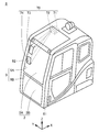
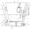
- FIG. 2 is a diagram for explaining the configuration of the cab 8. Specifically, FIG. 2 is a diagram for explaining the display system 40 provided in the cab 8.
- the cab 8 includes a window 9, a windshield 2 provided on the window 9, two front pillars 91 and 92, and a display device 70.
- the display device 70 includes a projector 71, a lens optical system 72, and two display units 73 and 74.
- the window 9 includes a window 9A and a window 9B below the window 9A.
- the windshield 2 includes a windshield 2A provided on the window 9A and a windshield 2B provided on the window 9B.
- the front pillar 91 is the left front pillar as viewed from the operator seated in the driver's seat of the cab 8.
- the front pillar 92 is a right front pillar as viewed from the operator. Further, the front pillar 92 is located closer to the work machine 4 than the front pillar 91.
- the front pillars 91 and 92 are also referred to as “A pillars”.
- the windshields 2A and 2B are installed between the front pillar 91 and the front pillar 92.
- the windshield 2 may be comprised with one sheet of glass.
- Projector 71 is a projector.
- the lens optical system 72 is installed between the projector 71 and the display units 73 and 74.
- the lens optical system 72 has a plurality of lenses. In the lens optical system 72, some of the plurality of lenses are movable in the optical axis direction.
- the display units 73 and 74 function as a head-up display that directly displays an image in the visual field of the operator.
- the display units 73 and 74 display work support information superimposed on the actual scene of the work site.
- Each of the display units 73 and 74 can be realized using a combiner.
- each of the display units 73 and 74 includes a combiner (see the combiners 731 and 741 in FIG. 4) and an attachment member for attaching the combiner to the front pillar 92 (the attachment members 732 and 742 in FIG. 4). Reference).
- the mounting positions of the display units 73 and 74 will be described later.
- Each combiner consists of a half mirror that reflects part of the light and transmits the rest of the light.
- Each combiner reflects the image projected by the projector 71 to the operator side in the cab 8 and transmits light from outside the cab 8 into the cab 8.
- the operator can grasp the image projected on each combiner as a virtual image displayed superimposed on the real scene in front of the cab 8.
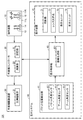
- FIG. 3 is a block diagram showing a configuration of a control system provided in work vehicle 101. As illustrated in FIG. 3, the work vehicle 101 includes an operation device 10, a work machine controller 20, a work machine drive device 30, and a display system 40.
- the operation device 10 includes operation members 11L and 11R, an operation detection unit 12, a travel operation member 13, and a travel operation detection unit 14.
- the operation members 11L and 11R are used for the operation of the work machine 4 and the swing body 3. Specifically, the operation member 11 ⁇ / b> R is used for an operator to operate the boom 5 and the bucket 7. The operation member 11L is used for an operator to operate the swing body 3 and the arm 6.
- the operation detection unit 12 detects an operator's operation on the operation members 11L and 11R.
- the traveling operation member 13 is used for an operator to operate the traveling of the work vehicle 101.
- the travel operation detection unit 14 detects an operator's operation on the travel operation member 13.
- the work vehicle 101 moves at a speed corresponding to the operation amount of the travel operation member 13.
- the work machine controller 20 includes a storage unit 21 and a calculation unit 22.
- the storage unit 21 includes a memory such as a RAM (Random Access Memory) and a ROM (Read Only Memory).
- the calculation unit 22 is configured by a calculation processing device such as a CPU (Central Processing Unit).
- the work machine controller 20 mainly controls the operation of the work machine 4 and the turning of the revolving structure 3. Specifically, the work machine controller 20 generates a control signal for operating the work machine 4 and the swing body 3 in accordance with the operation of the operation members 11L and 11R. The work machine controller 20 outputs the generated control signal to the work machine drive device 30.
- the work machine drive device 30 has a proportional solenoid valve 31.
- the proportional solenoid valve 31 operates based on a control signal from the work machine controller 20.
- the proportional solenoid valve 31 supplies hydraulic oil at a flow rate corresponding to the control signal to the hydraulic cylinder and the swing motor. Thereby, the working machine 4 operates and the revolving structure 3 turns.
- the display system 40 includes a bucket position detection unit 41, a display control unit 43, and a display device 70.
- the bucket position detection unit 41 includes a bucket angle sensor 411, an arm angle sensor 412, and a boom angle sensor 413.
- the bucket angle sensor 411 detects a relative angle of the bucket 7 from a predetermined reference position.
- the arm angle sensor 412 detects a relative angle of the arm 6 from a predetermined reference position.
- the boom angle sensor 413 detects a relative angle of the boom 5 from a predetermined reference position.
- the bucket position detection unit 41 detects the position of the bucket 7 with respect to the work vehicle main body based on the detected information on the three relative angles. Specifically, the position of the bucket 7 in the vehicle body coordinate system is detected. The bucket position detection unit 41 detects the position of the cutting edge 7 ⁇ / b> A of the bucket 7 as the position of the bucket 7, for example.
- the display control unit 43 causes the display units 73 and 74 to display various images such as information (work support information) for supporting the operation (work) of the work machine 4 by the operator.
- the display control unit 43 causes the display units 73 and 74 to display work support information using the detected position of the bucket 7 (for example, a light bar indicating the distance between the design landform and the cutting edge 7A).
- the display control unit 43 will be described in further detail as follows.
- the display control unit 43 includes an image generation unit 431.
- the image generation unit 431 generates an image to be displayed on the display units 73 and 74.
- the image generation unit 431 generates an image representing a vehicle speedometer, an engine tachometer, a fuel gauge, an oil temperature gauge, and the like. Further, the image generation unit 431 generates an image representing a plurality of work support information.
- the image generation unit 431 is connected to a controller (not shown) that controls the power system of the work vehicle 101.
- the image generation unit 431 receives information detected by various sensors, information related to control contents by the controller, and the like.
- the image generation unit 431 generates an image to be displayed on the display units 73 and 74 based on the received information.
- the display device 70 includes the projector 71, the lens optical system 72, and the display units 73 and 74.
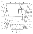
- FIG. 4 is a diagram showing the attachment positions of the display units 73 and 74. Referring to FIG. 4, display unit 73 and display unit 74 are provided along the front pillar at different positions. Each of the display unit 73 and the display unit 74 is installed along the front pillar 92 so that the display unit 73 is located above the display unit 74.
- the display unit 73 includes a combiner 731 and an attachment member 732.
- the combiner 731 is attached to the front pillar 92 by an attachment member 732.
- the display unit 74 includes a combiner 741 and an attachment member 742.
- the combiner 741 is attached to the front pillar 92 by an attachment member 742.
- the combiners 731 and 741 do not have a frame surrounding the outer edge.
- the attachment member 732 is attached to the front pillar 92 at a position above the attachment member 742. Accordingly, the combiner 731 can be disposed above the combiner 741 along the front pillar 92.
- the two display units 73 and 74 that are head-up displays are installed along the front pillar 92 in the vertical direction. Therefore, the head-up display can reduce a decrease in front visibility when viewed from the cab 8. In particular, the visibility of the central portion of the windshield 2 does not decrease. Therefore, the work vehicle 101 is excellent in visibility such as a real scene at the work site.
- the head-up display is disposed along the front pillar 92 closer to the work machine 4 than the front pillar 91, the head-up display is operated in comparison with the configuration in which the head-up display is disposed along the left front pillar 91.
- the amount of movement of the line of sight of the operator when operating the machine 4 can be reduced.
- the display unit 73 and the display unit 74 are installed at different positions (specifically, installed side by side in the vertical direction), the operator can use the two display units 73 and 73 to perform various information such as work support information. Can be confirmed.
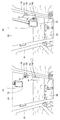
- FIG. 5 is a diagram for explaining the angle adjustment function of the combiners 731 and 741.
- each of the display units 73 and 74 has a function of adjusting the tilt angle of the display surface with respect to the horizontal plane (an angle adjusting function capable of tilting each display surface in the front-rear direction).
- the attachment members 732 and 742 have a mechanism for rotating the combiners 731 and 741 in the direction of the arrows in the figure.
- the display unit 73 can rotate the upper and lower ends of the combiner 731 in the front-rear direction with respect to the operator.
- the display unit 74 can also rotate the upper end and lower end of the combiner 741 in the front-rear direction with respect to the operator, as indicated by the arrows.
- the display units 73 and 74 can adjust the vertical angle of the combiners 731 and 741. Therefore, the vertical angle of each display surface can be adjusted to an angle suitable for the operator.
- the angle between the display surface of the display unit 73 and the horizontal plane is preferably set to be larger than the angle between the display surface of the display unit 74 and the horizontal plane.
- the angle ⁇ 1 between the main surface of the upper combiner 731 and the horizontal plane H is set larger than the angle ⁇ 2 between the main surface of the lower combiner 741 and the horizontal plane H ( ⁇ 1> ⁇ 2).
- the “main surface” is a surface onto which an image from the lens optical system 72 is projected.
- the display surface of the display unit 74 below the display unit 73 (the main surface of the combiner 741) is in a state of sleeping than the display surface of the display unit 73 (the main surface of the combiner 731). Accordingly, the display unit 73, the angle ⁇ 1 between the display surface of the display unit 73 and the horizontal plane H is smaller than the angle ⁇ 2 between the display surface of the display unit 74 and the horizontal plane H ( ⁇ 1 ⁇ 2). The visibility of the display content (work support information etc.) in 74 can be improved.
- FIG. 6 is a diagram for explaining the details of the mounting positions of the display units 73 and 74.
- the display unit 73 is installed at a distance d from the display unit 74.
- the mounting position of the display unit 73 to the front pillar 92 and the mounting position of the display unit 74 to the front pillar 92 are separated by a distance d.
- the horizontal width W of the display surface of the display units 73 and 74 is narrower than the distance d.
- the width W of the combiners 731 and 741 is shorter than the distance (distance d) between the mounting position of the display unit 73 and the mounting position of the display unit 74.
- the lateral width W is viewed from the operator's cab as compared with a configuration (W> d) wider than the interval (distance d) between the mounting position of the display unit 73 and the mounting position of the display unit 74.
- the front visibility (particularly, the visibility of the central portion of the windshield 2) can be improved.
- each of the combiners 731 and 741 does not have a frame surrounding the outer edge of the display surface
- the display is compared with a hardware configuration having a frame (bezel) surrounding the outer edge of the display surface.
- the area can be widened.
- the work machine 4, the cab 8, the front pillar 92, the display unit 73, the display unit 74, the combiners 731 and 741, and the mounting members 732 and 742 are the “work machine”, “cab”, and “front” of the present invention, respectively. It is an example of “pillar”, “first display section”, “second display section”, “combiner”, and “mounting member”.
- the display system 40 has a plurality of display modes.
- the display system 40 receives a display mode selection from the operator.
- the display system 40 controls the display contents of the display units 73 and 74 according to the received display mode.
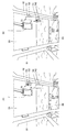
- FIG. 7 is a diagram for explaining the first display example. As shown in the states (A) and (B) of FIG. 7, the display control unit 43 causes the display unit 73 and the display unit 74 to simultaneously display work support information.
- the display control unit 43 causes the display unit 73 and the display unit 74 to display the same work support information as shown in the state (A) of FIG. .
- the display control unit 43 causes the display unit 73 to display first work support information, and causes the display unit 74 to display second work support information that is the same information as the first work support information.
- the display control unit 43 causes the display unit 73 and the display unit 74 to display different work support information as shown in the state (B) of FIG.
- the display control unit 43 causes the display unit 73 to display first work support information, and causes the display unit 74 to display second work support information that is different from the first work support information.
- the first work support information and the second work support information that is the same information as the first work support information are used as the front compass (the upper image in the display units 73 and 74. ) And a cross section of the design terrain and the cutting edge (lower images in the display units 73 and 74) are displayed.
- the facing compass represents whether the work vehicle 101 is in a state of facing the design terrain data.
- the light bar (the left image in the display unit 74), the design landform, An example is shown in which distance information (a right image on the display unit 74) representing the distance to the blade edge 7A is displayed.
- the light bar represents the distance between the design topography and the cutting edge 7A as a figure.
- the display control unit 43 causes the display unit 73 and the display unit 74 to simultaneously display the same work support information. According to this configuration, when confirming the work support information, the operator can obtain information only by confirming the display of the display unit 73 and the display unit 74 that has the smaller eye movement amount.
- the display control unit 43 causes the display unit 73 and the display unit 74 to simultaneously display different work support information.
- the display system 40 can display more types of work support information than when the first display mode is set. Therefore, the operator can view more information at the same time than when the first display mode is set.
- FIG. 8 is a diagram for explaining a second display example. As shown in the states (A) and (B) of FIG. 8, the display control unit 43 displays work support information on one of the display unit 73 and the display unit 74.
- the display control unit 43 operates only on the display unit 73 of the display unit 73 and the display unit 74 as shown in the state (A) of FIG. Display support information.
- the display control unit 43 supports the display unit 73 and the display unit 74 among the display units 74 only as shown in the state (B) of FIG. Display information.
- the work support information displayed on the display unit 73 and the fourth display mode are displayed.
- the work support information displayed on the display unit 74 when set is the same (specifically, the same type of information).
- the display control unit 43 sets the work support information that is a display target to one of the display unit 73 and the display unit 74. Display. According to such a configuration, the display system 40 can reduce power consumption consumed by the display system 40.
- FIG. 9 is a diagram for explaining a third display example. As shown in the states (A) and (B) of FIG. 9, the display control unit 43 determines whether the work support information is displayed on the display unit 73 or the display unit 74 according to the position of the bucket 7. decide.
- the display control unit 43 When the position of the bucket 7 is higher than a predetermined position, the display control unit 43 displays the work support information only on the display unit 73 of the display unit 73 and the display unit 74. In addition, when the position of the bucket 7 is lower than a predetermined position, the display control unit 43 displays the work support information only on the display unit 74 of the display unit 73 and the display unit 74.
- the position of the bucket 7 is typically specified as the position of the cutting edge 7A of the bucket 7.
- the display control unit 43 changes the display unit that displays the work support information from the display unit 73 to the lower side. Switch to the display unit 74. Further, when the position of the bucket 7 transitions from a position lower than the predetermined position to a higher position, the display control unit 43 displays a display unit that displays work support information from the display unit 74 upward. Switch to unit 73.
- the work support information when the operator confirms the work support information, the work support information is displayed only on the display unit 74 when the bucket is at a position higher than a predetermined position. Gaze movement can be reduced.
- the operator's line-of-sight movement is reduced compared to a configuration in which the work support information is displayed only on the display unit 73 when the bucket is at a position lower than a predetermined position. Can do.
- Each of the display unit 73 and the display unit 74 may be attached to the front pillar 92 so as to be slidable along the extending direction of the front pillar 92.
- FIG. 10 is a diagram for explaining the slide of the display units 73 and 74.
- the operator can slide the combiner 731 along the extending direction of the front pillar 92 by sliding the attachment member 732 of the display unit 73 along the extending direction of the front pillar 92.
- the operator can slide the combiner 741 along the extending direction of the front pillar 92 by sliding the mounting member 742 of the display unit 74 along the extending direction of the front pillar 92.
- the operator can set the mounting position of each of the display unit 73 and the display unit 74 to his / her preferred height.
- the display control unit 43 acquires information on the mounting positions of the display units 73 and 74 (specifically, the coordinates of the combiners 731 and 741), and based on the acquired information.
- the display system 40 may be configured to control the projection position of an image such as work support information.
- information on the mounting position for example, height information
- You may acquire the information of the said attachment position.
- the acquisition method of the information of the attachment position of the display units 73 and 74 is not specifically limited.
- Each of the display unit 73 and the display unit 74 is preferably attached to the front pillar 92 so as to be detachable from the front pillar 92. According to such a structure, it can also be set as the structure which has only one display unit, for example. Further, compared to a configuration in which the front pillar 92 is not detachable, the display unit is superior in terms of maintenance.
- the configuration in which the work vehicle 101 includes two display units has been described as an example.
- the configuration in which the display system 40 includes two combiners 731 and 741 has been described as an example.
- the number of display systems and the number of combiners are not limited to two and may be three or more.
- the display units 73 and 74 have been described by way of example of the configuration including the combiners 731 and 741, respectively.
- the present invention is not limited to this.
- it may be configured such that an operator visually recognizes an image projected on a film instead of a virtual image.
- a first film that transmits external light incident on the cab 8 is used, and a second film that transmits external light incident on the cab 8 is used instead of the display unit 74.
- the film may be used.
- each of the first film and the second film is installed along the front pillar 92 so that the first film is positioned above the second film.
- the first film and the second film function as a head-up display.
- the first film and the second film are examples of the “first display portion” and the “second display portion” in the present invention.
- the operator of the operator cab 8 can see the actual scene of the work site including the work machine 4 through the first film or the second film. Therefore, even in such a configuration, the visibility of the central portion of the windshield is not deteriorated by the head-up display. Therefore, the work vehicle 101 is excellent in visibility such as a real scene at the work site.
- a transparent first display for example, a transmissive liquid crystal display
- the display unit 74 the cab is used.
- a transparent second display that transmits external light incident on the light 8 may be used.
- each of the first display and the second display is installed along the front pillar 92 so that the first display is located above the second display.
- the first display and the second display function as a head-up display.
- the first display and the second display are examples of the “first display unit” and the “second display unit” in the present invention.
- the visibility of the central portion of the windshield is not lowered by the head-up display, as in the case of using the combiners 731 and 741, the first film and the second film. Therefore, the work vehicle 101 is excellent in visibility such as a real scene at the work site.
Landscapes
- Engineering & Computer Science (AREA)
- Mining & Mineral Resources (AREA)
- Civil Engineering (AREA)
- General Engineering & Computer Science (AREA)
- Structural Engineering (AREA)
- Mechanical Engineering (AREA)
- Component Parts Of Construction Machinery (AREA)
- Instrument Panels (AREA)
Abstract
Priority Applications (4)
| Application Number | Priority Date | Filing Date | Title |
|---|---|---|---|
| US16/060,169 US20180363273A1 (en) | 2016-02-16 | 2017-01-20 | Work vehicle |
| DE112017000204.4T DE112017000204T5 (de) | 2016-02-16 | 2017-01-20 | Arbeitsfahrzeug |
| CN201780004276.9A CN108291392A (zh) | 2016-02-16 | 2017-01-20 | 作业车辆 |
| KR1020187014167A KR102088786B1 (ko) | 2016-02-16 | 2017-01-20 | 작업 차량 |
Applications Claiming Priority (2)
| Application Number | Priority Date | Filing Date | Title |
|---|---|---|---|
| JP2016026987A JP6813268B2 (ja) | 2016-02-16 | 2016-02-16 | 作業車両 |
| JP2016-026987 | 2016-02-16 |
Publications (1)
| Publication Number | Publication Date |
|---|---|
| WO2017141620A1 true WO2017141620A1 (fr) | 2017-08-24 |
Family
ID=59625760
Family Applications (1)
| Application Number | Title | Priority Date | Filing Date |
|---|---|---|---|
| PCT/JP2017/001869 Ceased WO2017141620A1 (fr) | 2016-02-16 | 2017-01-20 | Engin de chantier |
Country Status (6)
| Country | Link |
|---|---|
| US (1) | US20180363273A1 (fr) |
| JP (1) | JP6813268B2 (fr) |
| KR (1) | KR102088786B1 (fr) |
| CN (1) | CN108291392A (fr) |
| DE (1) | DE112017000204T5 (fr) |
| WO (1) | WO2017141620A1 (fr) |
Families Citing this family (4)
| Publication number | Priority date | Publication date | Assignee | Title |
|---|---|---|---|---|
| WO2019163378A1 (fr) * | 2018-02-23 | 2019-08-29 | コニカミノルタ株式会社 | Dispositif de traitement des images de chariot élévateur et programme de commande |
| JP7473305B2 (ja) * | 2019-07-10 | 2024-04-23 | 株式会社小松製作所 | キャブおよび作業車両 |
| CN112965682A (zh) | 2021-04-08 | 2021-06-15 | 上海三一重机股份有限公司 | 作业机械的辅助显示方法、装置、系统及电子设备 |
| EP4424924A4 (fr) * | 2021-10-28 | 2025-10-15 | Hitachi Construction Machinery Tierra Co Ltd | Cabine pour machine de construction |
Citations (7)
| Publication number | Priority date | Publication date | Assignee | Title |
|---|---|---|---|---|
| US20050256607A1 (en) * | 2004-05-11 | 2005-11-17 | J.C. Bamford Excavators Limited | Operator display system |
| JP2009173195A (ja) * | 2008-01-25 | 2009-08-06 | Sumitomo (Shi) Construction Machinery Manufacturing Co Ltd | 建設機械用表示システム |
| JP2009214558A (ja) * | 2008-03-06 | 2009-09-24 | Yanmar Co Ltd | フロントガラス |
| JP2011038346A (ja) * | 2009-08-13 | 2011-02-24 | Hitachi Constr Mach Co Ltd | 建設機械 |
| JP2013036243A (ja) * | 2011-08-09 | 2013-02-21 | Topcon Corp | 建設機械制御システム |
| JP2014129676A (ja) * | 2012-12-28 | 2014-07-10 | Komatsu Ltd | 建設機械の表示システムおよびその制御方法 |
| JP2015063864A (ja) * | 2013-09-26 | 2015-04-09 | 住友建機株式会社 | ショベル、及びショベル用管理装置 |
Family Cites Families (23)
| Publication number | Priority date | Publication date | Assignee | Title |
|---|---|---|---|---|
| US5422812A (en) * | 1985-05-30 | 1995-06-06 | Robert Bosch Gmbh | Enroute vehicle guidance system with heads up display |
| FR2696013B1 (fr) * | 1992-09-21 | 1994-11-25 | Sextant Avionique | Combineur holographique escamotable, notamment pour aéronef. |
| EP1398601A3 (fr) * | 2002-09-13 | 2014-05-07 | Canon Kabushiki Kaisha | Afficheur tête haute pour navigation dans un véhicule |
| US7158095B2 (en) * | 2003-07-17 | 2007-01-02 | Big Buddy Performance, Inc. | Visual display system for displaying virtual images onto a field of vision |
| JP2007008284A (ja) | 2005-06-29 | 2007-01-18 | Shin Caterpillar Mitsubishi Ltd | 作業機械用表示装置 |
| IL179135A (en) * | 2005-11-10 | 2010-11-30 | Elbit Systems Electro Optics Elop Ltd | Head up display mechanism |
| US7520694B2 (en) * | 2007-02-03 | 2009-04-21 | Joe Dvoracek | Flexible traffic reflector |
| US20090219199A1 (en) * | 2008-02-29 | 2009-09-03 | Caterpillar Inc. | Positioning system for projecting a site model |
| JP5548880B2 (ja) * | 2010-04-26 | 2014-07-16 | 日立建機株式会社 | 作業機械の表示装置 |
| DE102011118853A1 (de) * | 2011-08-18 | 2013-02-21 | Johnson Controls Gmbh | Anzeigevorrichtung |
| JP5841008B2 (ja) * | 2012-05-28 | 2016-01-06 | ヤンマー株式会社 | 旋回作業車 |
| JP5465345B1 (ja) * | 2013-01-18 | 2014-04-09 | 株式会社小松製作所 | 油圧ショベル |
| US9674413B1 (en) * | 2013-04-17 | 2017-06-06 | Rockwell Collins, Inc. | Vision system and method having improved performance and solar mitigation |
| JP6205595B2 (ja) * | 2013-04-23 | 2017-10-04 | カルソニックカンセイ株式会社 | 車両用表示装置 |
| JP5706051B1 (ja) * | 2014-04-24 | 2015-04-22 | 株式会社小松製作所 | 作業車両 |
| JP6382305B2 (ja) * | 2014-05-09 | 2018-08-29 | マクセル株式会社 | ヘッドアップディスプレイ装置 |
| US9824490B1 (en) * | 2015-06-08 | 2017-11-21 | Bentley Systems, Incorporated | Augmentation of a dynamic terrain surface |
| WO2017013969A1 (fr) * | 2015-07-21 | 2017-01-26 | コニカミノルタ株式会社 | Matrice de moulage et composant optique en forme de plaque fabriqué à l'aide de celui-ci et procédé de fabrication associé |
| CN107921870A (zh) * | 2015-09-10 | 2018-04-17 | 富士胶片株式会社 | 投影型显示装置及投影控制方法 |
| CN108027515A (zh) * | 2015-09-25 | 2018-05-11 | 富士胶片株式会社 | 投影型显示装置及投影控制方法 |
| US20180277067A1 (en) * | 2015-09-30 | 2018-09-27 | Agco Corporation | User Interface for Mobile Machines |
| US20170090741A1 (en) * | 2015-09-30 | 2017-03-30 | Agco Corporation | User Interface for Mobile Machines |
| JP6707344B2 (ja) * | 2015-12-25 | 2020-06-10 | 株式会社小松製作所 | 作業車両および作業車両の制御方法 |
-
2016
- 2016-02-16 JP JP2016026987A patent/JP6813268B2/ja active Active
-
2017
- 2017-01-20 US US16/060,169 patent/US20180363273A1/en not_active Abandoned
- 2017-01-20 CN CN201780004276.9A patent/CN108291392A/zh active Pending
- 2017-01-20 DE DE112017000204.4T patent/DE112017000204T5/de not_active Withdrawn
- 2017-01-20 WO PCT/JP2017/001869 patent/WO2017141620A1/fr not_active Ceased
- 2017-01-20 KR KR1020187014167A patent/KR102088786B1/ko active Active
Patent Citations (7)
| Publication number | Priority date | Publication date | Assignee | Title |
|---|---|---|---|---|
| US20050256607A1 (en) * | 2004-05-11 | 2005-11-17 | J.C. Bamford Excavators Limited | Operator display system |
| JP2009173195A (ja) * | 2008-01-25 | 2009-08-06 | Sumitomo (Shi) Construction Machinery Manufacturing Co Ltd | 建設機械用表示システム |
| JP2009214558A (ja) * | 2008-03-06 | 2009-09-24 | Yanmar Co Ltd | フロントガラス |
| JP2011038346A (ja) * | 2009-08-13 | 2011-02-24 | Hitachi Constr Mach Co Ltd | 建設機械 |
| JP2013036243A (ja) * | 2011-08-09 | 2013-02-21 | Topcon Corp | 建設機械制御システム |
| JP2014129676A (ja) * | 2012-12-28 | 2014-07-10 | Komatsu Ltd | 建設機械の表示システムおよびその制御方法 |
| JP2015063864A (ja) * | 2013-09-26 | 2015-04-09 | 住友建機株式会社 | ショベル、及びショベル用管理装置 |
Also Published As
| Publication number | Publication date |
|---|---|
| KR20180071331A (ko) | 2018-06-27 |
| JP2017145586A (ja) | 2017-08-24 |
| US20180363273A1 (en) | 2018-12-20 |
| KR102088786B1 (ko) | 2020-03-13 |
| CN108291392A (zh) | 2018-07-17 |
| DE112017000204T5 (de) | 2018-08-09 |
| JP6813268B2 (ja) | 2021-01-13 |
Similar Documents
| Publication | Publication Date | Title |
|---|---|---|
| CN108368694B (zh) | 作业车辆以及显示控制方法 | |
| KR101815268B1 (ko) | 건설 기계의 표시 시스템 및 그 제어 방법 | |
| US20190308502A1 (en) | Projection display device, method for controlling projection display device, and program for controlling projection display device | |
| WO2017141620A1 (fr) | Engin de chantier | |
| JP7490127B2 (ja) | モータグレーダおよび表示制御方法 | |
| CN108291391B (zh) | 作业车辆以及显示控制方法 | |
| CN108291388B (zh) | 作业车辆以及作业车辆的控制方法 | |
| JP2017186901A (ja) | 建設機械の表示システムおよびその制御方法 | |
| JP2019015176A (ja) | 建設機械の表示システムおよびその制御方法 | |
| JPWO2020090187A1 (ja) | 虚像表示装置、およびヘッドアップディスプレイ装置 | |
| CN108291389B (zh) | 作业车辆以及作业车辆的控制方法 | |
| JP2013002101A (ja) | 作業機械の視野補助装置 | |
| JP7168697B2 (ja) | 建設機械の表示システムおよびその制御方法 | |
| WO2019017040A1 (fr) | Dispositif d'affichage de type à projection, procédé de commande de dispositif d'affichage de type à projection, et programme de commande de dispositif d'affichage de type à projection |
Legal Events
| Date | Code | Title | Description |
|---|---|---|---|
| 121 | Ep: the epo has been informed by wipo that ep was designated in this application |
Ref document number: 17752884 Country of ref document: EP Kind code of ref document: A1 |
|
| ENP | Entry into the national phase |
Ref document number: 20187014167 Country of ref document: KR Kind code of ref document: A |
|
| WWE | Wipo information: entry into national phase |
Ref document number: 112017000204 Country of ref document: DE |
|
| 122 | Ep: pct application non-entry in european phase |
Ref document number: 17752884 Country of ref document: EP Kind code of ref document: A1 |