WO2017141957A1 - Dispositif de mesure de distance - Google Patents
Dispositif de mesure de distance Download PDFInfo
- Publication number
- WO2017141957A1 WO2017141957A1 PCT/JP2017/005503 JP2017005503W WO2017141957A1 WO 2017141957 A1 WO2017141957 A1 WO 2017141957A1 JP 2017005503 W JP2017005503 W JP 2017005503W WO 2017141957 A1 WO2017141957 A1 WO 2017141957A1
- Authority
- WO
- WIPO (PCT)
- Prior art keywords
- measurement
- period
- distance
- light
- time
- Prior art date
- Legal status (The legal status is an assumption and is not a legal conclusion. Google has not performed a legal analysis and makes no representation as to the accuracy of the status listed.)
- Ceased
Links
Images











Classifications
-
- G—PHYSICS
- G01—MEASURING; TESTING
- G01S—RADIO DIRECTION-FINDING; RADIO NAVIGATION; DETERMINING DISTANCE OR VELOCITY BY USE OF RADIO WAVES; LOCATING OR PRESENCE-DETECTING BY USE OF THE REFLECTION OR RERADIATION OF RADIO WAVES; ANALOGOUS ARRANGEMENTS USING OTHER WAVES
- G01S17/00—Systems using the reflection or reradiation of electromagnetic waves other than radio waves, e.g. lidar systems
- G01S17/02—Systems using the reflection of electromagnetic waves other than radio waves
- G01S17/06—Systems determining position data of a target
- G01S17/08—Systems determining position data of a target for measuring distance only
- G01S17/10—Systems determining position data of a target for measuring distance only using transmission of interrupted, pulse-modulated waves
- G01S17/14—Systems determining position data of a target for measuring distance only using transmission of interrupted, pulse-modulated waves wherein a voltage or current pulse is initiated and terminated in accordance with the pulse transmission and echo reception respectively, e.g. using counters
-
- G—PHYSICS
- G01—MEASURING; TESTING
- G01S—RADIO DIRECTION-FINDING; RADIO NAVIGATION; DETERMINING DISTANCE OR VELOCITY BY USE OF RADIO WAVES; LOCATING OR PRESENCE-DETECTING BY USE OF THE REFLECTION OR RERADIATION OF RADIO WAVES; ANALOGOUS ARRANGEMENTS USING OTHER WAVES
- G01S17/00—Systems using the reflection or reradiation of electromagnetic waves other than radio waves, e.g. lidar systems
- G01S17/02—Systems using the reflection of electromagnetic waves other than radio waves
- G01S17/04—Systems determining the presence of a target
-
- G—PHYSICS
- G01—MEASURING; TESTING
- G01S—RADIO DIRECTION-FINDING; RADIO NAVIGATION; DETERMINING DISTANCE OR VELOCITY BY USE OF RADIO WAVES; LOCATING OR PRESENCE-DETECTING BY USE OF THE REFLECTION OR RERADIATION OF RADIO WAVES; ANALOGOUS ARRANGEMENTS USING OTHER WAVES
- G01S17/00—Systems using the reflection or reradiation of electromagnetic waves other than radio waves, e.g. lidar systems
- G01S17/02—Systems using the reflection of electromagnetic waves other than radio waves
- G01S17/06—Systems determining position data of a target
- G01S17/08—Systems determining position data of a target for measuring distance only
- G01S17/10—Systems determining position data of a target for measuring distance only using transmission of interrupted, pulse-modulated waves
-
- G—PHYSICS
- G01—MEASURING; TESTING
- G01S—RADIO DIRECTION-FINDING; RADIO NAVIGATION; DETERMINING DISTANCE OR VELOCITY BY USE OF RADIO WAVES; LOCATING OR PRESENCE-DETECTING BY USE OF THE REFLECTION OR RERADIATION OF RADIO WAVES; ANALOGOUS ARRANGEMENTS USING OTHER WAVES
- G01S17/00—Systems using the reflection or reradiation of electromagnetic waves other than radio waves, e.g. lidar systems
- G01S17/02—Systems using the reflection of electromagnetic waves other than radio waves
- G01S17/06—Systems determining position data of a target
- G01S17/08—Systems determining position data of a target for measuring distance only
- G01S17/10—Systems determining position data of a target for measuring distance only using transmission of interrupted, pulse-modulated waves
- G01S17/18—Systems determining position data of a target for measuring distance only using transmission of interrupted, pulse-modulated waves wherein range gates are used
-
- G—PHYSICS
- G01—MEASURING; TESTING
- G01S—RADIO DIRECTION-FINDING; RADIO NAVIGATION; DETERMINING DISTANCE OR VELOCITY BY USE OF RADIO WAVES; LOCATING OR PRESENCE-DETECTING BY USE OF THE REFLECTION OR RERADIATION OF RADIO WAVES; ANALOGOUS ARRANGEMENTS USING OTHER WAVES
- G01S17/00—Systems using the reflection or reradiation of electromagnetic waves other than radio waves, e.g. lidar systems
- G01S17/02—Systems using the reflection of electromagnetic waves other than radio waves
- G01S17/06—Systems determining position data of a target
- G01S17/08—Systems determining position data of a target for measuring distance only
- G01S17/32—Systems determining position data of a target for measuring distance only using transmission of continuous waves, whether amplitude-, frequency-, or phase-modulated, or unmodulated
- G01S17/36—Systems determining position data of a target for measuring distance only using transmission of continuous waves, whether amplitude-, frequency-, or phase-modulated, or unmodulated with phase comparison between the received signal and the contemporaneously transmitted signal
-
- G—PHYSICS
- G01—MEASURING; TESTING
- G01S—RADIO DIRECTION-FINDING; RADIO NAVIGATION; DETERMINING DISTANCE OR VELOCITY BY USE OF RADIO WAVES; LOCATING OR PRESENCE-DETECTING BY USE OF THE REFLECTION OR RERADIATION OF RADIO WAVES; ANALOGOUS ARRANGEMENTS USING OTHER WAVES
- G01S17/00—Systems using the reflection or reradiation of electromagnetic waves other than radio waves, e.g. lidar systems
- G01S17/86—Combinations of lidar systems with systems other than lidar, radar or sonar, e.g. with direction finders
-
- G—PHYSICS
- G01—MEASURING; TESTING
- G01S—RADIO DIRECTION-FINDING; RADIO NAVIGATION; DETERMINING DISTANCE OR VELOCITY BY USE OF RADIO WAVES; LOCATING OR PRESENCE-DETECTING BY USE OF THE REFLECTION OR RERADIATION OF RADIO WAVES; ANALOGOUS ARRANGEMENTS USING OTHER WAVES
- G01S17/00—Systems using the reflection or reradiation of electromagnetic waves other than radio waves, e.g. lidar systems
- G01S17/88—Lidar systems specially adapted for specific applications
- G01S17/89—Lidar systems specially adapted for specific applications for mapping or imaging
- G01S17/894—Three-dimensional [3D] imaging with simultaneous measurement of time-of-flight at a two-dimensional [2D] array of receiver pixels, e.g. time-of-flight cameras or flash lidar
-
- G—PHYSICS
- G01—MEASURING; TESTING
- G01S—RADIO DIRECTION-FINDING; RADIO NAVIGATION; DETERMINING DISTANCE OR VELOCITY BY USE OF RADIO WAVES; LOCATING OR PRESENCE-DETECTING BY USE OF THE REFLECTION OR RERADIATION OF RADIO WAVES; ANALOGOUS ARRANGEMENTS USING OTHER WAVES
- G01S7/00—Details of systems according to groups G01S13/00, G01S15/00, G01S17/00
- G01S7/48—Details of systems according to groups G01S13/00, G01S15/00, G01S17/00 of systems according to group G01S17/00
- G01S7/483—Details of pulse systems
- G01S7/486—Receivers
- G01S7/4861—Circuits for detection, sampling, integration or read-out
- G01S7/4863—Detector arrays, e.g. charge-transfer gates
-
- G—PHYSICS
- G01—MEASURING; TESTING
- G01S—RADIO DIRECTION-FINDING; RADIO NAVIGATION; DETERMINING DISTANCE OR VELOCITY BY USE OF RADIO WAVES; LOCATING OR PRESENCE-DETECTING BY USE OF THE REFLECTION OR RERADIATION OF RADIO WAVES; ANALOGOUS ARRANGEMENTS USING OTHER WAVES
- G01S7/00—Details of systems according to groups G01S13/00, G01S15/00, G01S17/00
- G01S7/48—Details of systems according to groups G01S13/00, G01S15/00, G01S17/00 of systems according to group G01S17/00
- G01S7/483—Details of pulse systems
- G01S7/486—Receivers
- G01S7/4865—Time delay measurement, e.g. time-of-flight measurement, time of arrival measurement or determining the exact position of a peak
-
- G—PHYSICS
- G01—MEASURING; TESTING
- G01S—RADIO DIRECTION-FINDING; RADIO NAVIGATION; DETERMINING DISTANCE OR VELOCITY BY USE OF RADIO WAVES; LOCATING OR PRESENCE-DETECTING BY USE OF THE REFLECTION OR RERADIATION OF RADIO WAVES; ANALOGOUS ARRANGEMENTS USING OTHER WAVES
- G01S7/00—Details of systems according to groups G01S13/00, G01S15/00, G01S17/00
- G01S7/48—Details of systems according to groups G01S13/00, G01S15/00, G01S17/00 of systems according to group G01S17/00
- G01S7/483—Details of pulse systems
- G01S7/486—Receivers
- G01S7/487—Extracting wanted echo signals, e.g. pulse detection
-
- G—PHYSICS
- G01—MEASURING; TESTING
- G01S—RADIO DIRECTION-FINDING; RADIO NAVIGATION; DETERMINING DISTANCE OR VELOCITY BY USE OF RADIO WAVES; LOCATING OR PRESENCE-DETECTING BY USE OF THE REFLECTION OR RERADIATION OF RADIO WAVES; ANALOGOUS ARRANGEMENTS USING OTHER WAVES
- G01S7/00—Details of systems according to groups G01S13/00, G01S15/00, G01S17/00
- G01S7/48—Details of systems according to groups G01S13/00, G01S15/00, G01S17/00 of systems according to group G01S17/00
- G01S7/497—Means for monitoring or calibrating
Definitions
- the present disclosure relates to a distance measuring device.
- the measuring object As a distance measuring method from the distance measuring device to the object to be measured (hereinafter referred to as the measuring object), light is irradiated from the vicinity of the distance measuring device toward the measuring object, and then reflected by the object and returned to the distance measuring device.
- the TOF method Compared with other distance measurement methods such as the compound eye method, the TOF method has a disadvantage in that it requires a light source in addition to the distance measurement device, while if the light source is strengthened, the distance measurement of a distant object can be performed.
- the advantage is that it can be performed with high resolution.
- the TOF method has a problem that if the measurement range is set far, the measurement time becomes longer.
- a light pulse is emitted to the measurement object, and the reflected light from the measurement object is exposed at an exposure timing with a plurality of delay amounts synchronized with the light emission timing, and output at each exposure. Based on this, the distance to the object is calculated. Therefore, the farther the object to be measured is, the more intense the light pulse is required, so the longer the waiting time for preventing the deviation of the pair of light emission and exposure, which is necessary for one set of light emission and exposure. It takes a long time. Further, when the object to be measured is far away, in order to perform distance measurement with high distance resolution, it is necessary to execute many pairs of light emission and exposure, and the measurement time becomes long.
- the present disclosure has been made in view of the above circumstances, and a main purpose thereof is to provide a distance measuring device capable of efficiently measuring a distance.
- a distance measuring device includes a light emitting unit that emits outgoing light, and a light receiving unit that can receive reflected light reflected by the measurement object from the measuring object during exposure.
- a control unit that controls the light emitting unit and the light receiving unit, and a measurement target from the distance measuring device based on a time from when the light emitting unit emits emitted light to when the light receiving unit receives reflected light.
- a distance calculation unit that calculates a distance to the object, and an output unit that outputs the calculated distance, and the control unit is configured to output a time range corresponding to the first measurement distance range during the first period.
- a first measurement time range is set, and in the first measurement time range, the light emitting unit emits emitted light, the light receiving unit is in exposure, and the control unit is in a second period.
- Time range corresponding to the second measurement distance range A second measurement time range is set, and in the second measurement time range, the light emitting unit emits emitted light, the light receiving unit is exposed, and in the first period and the second period, , At least one measurement condition is different, and the distance calculation unit causes the reflection unit to reflect the reflection light from the time when the light emission unit emits light in at least one of the first period and the second period. The distance from the distance measuring device to the measurement object is calculated based on the time until the light is received.
- a distance measuring device includes a light emitting unit that emits emitted light, and a light receiving unit that can receive reflected light reflected by the measurement object from the emitted light during exposure. And a control unit that controls the light emitting unit and the light receiving unit, and the measurement from the distance measuring device based on the time from when the light emitted from the light emitting unit is emitted until the light receiving unit receives the reflected light.
- a distance calculation unit that calculates a distance to the object; and an output unit that outputs the calculated distance; and the control unit is a time range corresponding to the first measurement distance range during the first period.
- a first measurement time range is set, and in the first measurement time range, emitted light is emitted from the light emitting unit, the light receiving unit is being exposed, and the control unit Corresponding to the second measuring distance range during the period
- the second measurement time range which is an interval range, is divided into K ′ (K ′: a natural number of 2 or more) sections, and the repetition period including the time for emitting the light emitted from the light emitting unit and the second measurement time range
- K ′ K ′: a natural number of 2 or more
- FIG. 1 is a block diagram illustrating an example of a functional configuration of the distance measuring apparatus according to the first embodiment.
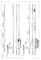
- FIG. 2 is a diagram illustrating an example of a measurement sequence of the distance measuring apparatus according to the first embodiment.
- FIG. 3 is a diagram illustrating an example of a measurement sequence of the distance measuring apparatus according to the second embodiment.
- FIG. 4 is a diagram illustrating another example of a measurement sequence of the distance measuring apparatus according to the second embodiment.
- FIG. 5 is a diagram illustrating another example of a distance measuring operation sequence of the distance measuring apparatus according to the second embodiment.
- FIG. 6A is a diagram showing another example of a distance measuring operation sequence of the distance measuring apparatus according to Embodiment 2.
- FIG. 1 is a block diagram illustrating an example of a functional configuration of the distance measuring apparatus according to the first embodiment.
- FIG. 2 is a diagram illustrating an example of a measurement sequence of the distance measuring apparatus according to the first embodiment.
- FIG. 3 is a diagram illustrating an example of a measurement
- FIG. 6B is a diagram showing another example of a distance measuring operation sequence of the distance measuring apparatus according to Embodiment 2.
- FIG. 6C is a diagram showing another example of a distance measuring operation sequence of the distance measuring apparatus according to Embodiment 2.
- FIG. 7 is a diagram illustrating an example of a distance measuring operation sequence of the distance measuring apparatus according to the third embodiment.
- FIG. 8 is a diagram illustrating an example of a distance measuring operation sequence of the distance measuring apparatus according to the fourth embodiment.
- FIG. 9 is a diagram illustrating an example of a distance measuring operation sequence of the distance measuring apparatus according to the fourth embodiment.
- FIG. 10 is a diagram illustrating an example of a distance measuring operation sequence of the distance measuring apparatus according to the fifth embodiment.
- FIG. 11 is a diagram illustrating an example of a circuit configuration of the pixel circuit according to Example 1 of the sixth embodiment.
- FIG. 12 is a diagram for explaining the relationship between the distance between the image sensor and the object and the image in the image sensor according to Example 2 of the sixth embodiment.
- FIG. 13 is an example of a distance image measured by the distance measuring apparatus according to Example 2 of the sixth embodiment.
- FIG. 14A is a schematic diagram for explaining an exposure sequence of the distance measuring apparatus according to Example 3 of Embodiment 6.
- FIG. 14B is a schematic diagram for explaining an exposure sequence of the distance measuring apparatus according to Example 3 of Embodiment 6.
- FIG. 15 is a diagram illustrating an example of an image sensor included in the light receiving unit according to Example 3 of the sixth embodiment.
- FIG. 16 is a diagram illustrating an example of an image sensor included in the light receiving unit according to Example 3 of the sixth embodiment.
- FIG. 17A is a diagram illustrating an example of an image sensor included in the light receiving unit according to Example 3 of the sixth embodiment.
- FIG. 17B is a diagram illustrating an example of a control circuit of the image sensor in FIG. 16.
- FIG. 18 is a diagram illustrating another example of the image sensor included in the light receiving unit according to Example 3 of the sixth embodiment.
- FIG. 19 is a diagram for describing an example of controlling the read time according to Example 3 of the sixth embodiment.
- FIG. 20 is a diagram illustrating an example of a circuit configuration of the pixel circuit according to the first embodiment.
- FIG. 20 is a diagram illustrating an example of a circuit configuration of the pixel circuit according to the first embodiment.
- FIG. 21 is a diagram for explaining that different results according to the distance to be measured can be obtained in the same exposure sequence for all pixels according to the fourth embodiment.
- FIG. 22 is a diagram showing a pixel circuit configuration and an exposure sequence according to the fifth embodiment.
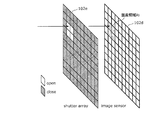
- FIG. 23A is a diagram for describing driving of the shutter array and the image sensor according to Example 2 of Embodiment 7.
- FIG. 23B is a diagram for describing driving of the shutter array and the image sensor according to Example 2 of Embodiment 7.
- FIG. 24 is a diagram illustrating an example of a distance measurement operation sequence of the distance measurement device according to the modification of the first embodiment.
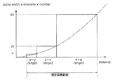
- FIG. 25 is a diagram for explaining the division distance section of the measurement distance range and the variation of the light source parameter for each division distance section.
- FIG. 1 is a block diagram illustrating an example of a functional configuration of a distance measuring device 10 according to the present embodiment.
- FIG. 1 includes a light-emitting unit 101, a light-receiving unit 102, a control unit 103, an output unit 104, and a distance calculation unit 105.
- FIG. 1 shows a measurement object 60 as an example.
- the light emitting unit 101 is controlled by the control unit 103 to emit emitted light.
- the light emitting unit 101 has a light source such as a laser light source, for example, and emits a light pulse (emitted light) by emitting light with a predetermined light pulse width.
- the intensity of the light pulse used for the light emitting unit 101 is, for example, about class 1 or class 2, and is not regarded as dangerous according to a predetermined safety standard.
- a single wavelength, short pulse, high intensity light source is suitable for distance measurement, and a pulse laser may be used. Further, a different light source such as a light emitting diode (LED) or a halogen lamp can be used as the light source.
- the wavelength of the light source may be the wavelength of infrared light in consideration of use in an urban area or the like, but is not particularly limited.
- the light receiving unit 102 is controlled by the control unit 103 to receive the reflected light reflected by the measurement object 60 from the emitted light.
- the light receiving unit 102 can receive reflected light while being controlled by the control unit 103 during exposure.
- the light receiving unit 102 is configured using, for example, a photodiode.
- the light receiving unit 102 may be an avalanche photodiode or a photomultiplier tube, or may be an image sensor in which light receiving elements are two-dimensionally arranged. In this case, the light receiving unit 102 may include an optical system such as a lens as necessary.
- one independent light receiving element is referred to as a pixel.
- data analysis such as image processing and recognition processing can be performed at a later stage.
- the light receiving unit 102 by providing the light receiving unit 102 with a filter that blocks or transmits light of a specific frequency, it is possible to obtain frequency information. That is, the right of the present disclosure is not limited depending on the configuration of the light receiving unit 102.
- the control unit 103 controls the light emitting unit 101 and the light receiving unit 102.
- the control unit 103 controls the light emitting unit 101 and the light receiving unit 102 under a predetermined measurement condition during the first period, and calculates the distance from the distance measuring device 10 to the measurement object 60 to the distance calculating unit 105.
- the control unit 103 divides the first measurement time range into K sections (K: a natural number of 2 or more) during the first period, and emits light emitted from the light emitting unit 101.
- the repetition period including the first measurement time range is repeated K times.
- the control unit 103 causes the light emitting unit 101 to emit light for each repetition period, and causes the light receiving unit 102 to be exposed during at least one of the K sections for each repetition period.
- the control unit 103 performs control so that the measurement conditions are different between the first period and the second period.
- the control unit 103 includes K measurement time ranges (K: a natural number of 1 or more) that are time ranges corresponding to the measurement distance range starting from the predetermined position during the first period. It divides
- the control unit 103 performs control so that the measurement period including at least the measurement distance range is different between the first period and the second period following the first period.
- the distance calculation unit 105 performs the distance measurement device 10 to the measurement object 60 based on the time from the time when the light emitted from the light emitting unit 101 is emitted during the first period and the second period to the time when the light receiving unit 102 receives the light. The distance is calculated.
- the output unit 104 outputs the calculated distance from the distance measuring device 10 to the measurement object 60.
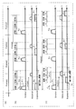
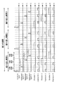
- FIG. 2 is a diagram showing an example of a distance measuring operation sequence of the distance measuring apparatus 10 according to the present embodiment.
- (A) in FIG. 2 shows a distance measurement sequence, and distance data is measured in each period separated by vertical lines.
- distance data is measured in one or more periods, and distance measurement is performed in measurement conditions different from those in other periods in at least one period.
- the measurement conditions here include the pulse period, pulse intensity, pulse width, and pulse train encoding method of the emitted light, the exposure time width of the light receiving unit 102, the exposure cycle, the number of exposures, and the method for controlling the drive circuit of the light receiving unit 102 And at least one of data processing methods such as an image reading range of the light receiving unit. Measurement conditions are not limited to the examples given above.
- luminance data measurement may be included. Further, the data may be output after the measurement in all the periods is completed, or the data may be output every time the measurement for one period is completed. A method of performing measurement while varying measurement conditions within one period is also included in the scope of the present disclosure.
- FIG. 2B shows an example of a sequence of emitted light, reflected light, and exposure within each measurement period. Note that the scope of rights of the present disclosure is not limited to the distance measurement method described with reference to FIG.
- the control unit 103 first determines a distance range l for performing distance measurement, and determines a measurement time range 2l / c that is a time range corresponding to this distance on the time axis. Next, the determined measurement time range is divided into one or a plurality of sections. The upper limit of the measurement time range of one section is determined by the intensity of the light source and the sensitivity of the light receiving unit 102, and the condition is that the pulsed light reflected by the measurement target can be detected by the light receiving unit 102. The pulsed light is emitted at least once in synchronization with the start of the measurement time range 2 l / c or with a predetermined time delay / preceding, and exposure is performed in at least one of the divided sections.
- a section where no exposure is performed may be provided. This operation is repeated as many times as the number of the divided sections, and in each operation, measurement is performed with different exposure sections. Since the optical signal can be detected only when the reflected light returns during exposure, the distance to be measured can be determined corresponding to the divided sections. Note that the scope of rights of the present disclosure is also applicable to cases where the number of divided sections and the number of repetitions are different, such as limiting the section in which exposure is performed.
- the lower limit of the repetition time is determined by the intensity of the emitted pulsed light and the sensitivity of the light receiving unit 102, and it is necessary that the intensity of the pulsed light is sufficiently attenuated so that no erroneous detection of light occurs in the next measurement.
- Measured time range, divided section, measured distance range, and distance resolution correspond as follows.
- the time t is expressed by the following (formula 1).
- c is the speed of light
- the numerical value “2” takes into account the amount of light emitted from the light source and the return.
- the measurement time range t a is equally divided into N intervals, 1,2,3 in order from the light-emitting time, shake ... and numbers.
- the width of d i is the ct a / 2N, it is possible to measure the distance to the measurement target and the self apparatus in this resolution.
- section division of the measurement time range may not be equally divided with the measurement time range, and an algorithm may be constructed in the distance measurement device 10 or may be arbitrarily set by the user.
- the control unit 103 causes the light emitting unit 101 to emit a light pulse (emitted light).
- the emitted light pulse is reflected after reaching the measurement object 60 at the distance d, and the reflected light returns to the distance measuring device 10 after time t from the emission (light emission) of the pulsed light.
- the control unit 103 performs control to cause the light receiving unit 102 to be exposed during the time range ti delayed by (Equation 3) from the time of light emission in accordance with the one divided section i.
- control unit 103 indicates a distance range corresponding to the time range ti when the light receiving unit 102 receives light (reflected light) having a signal intensity or higher set in advance within the time range ti (during exposure).
- a distance (a distance indicated by a minimum value, an average value, or the like) is stored as a distance to the measurement object 60 in a memory (not shown) or output to the output unit 104.
- the number of sections N is shows an example of a case 3, the light emitting unit 101, the light pulse every repetition period (P 11, P 12, P 13) of FIG. 2
- the light receiving unit 102 shows an example in which at least one of the divided sections (section 11, section 12, and section 13) is under exposure (exposure times E 11 , E 12, and E 13 ) for each repetition period. Has been.
- E 11 , E 12, and E 13 Exposure times E 11 , E 12, and E 13
- the exposure time E 13 is the exposure period in the third repetition period to during exposure.
- all sections are exposed during one period, but this is not necessary.
- a method may be used in which only the section 11 is exposed in the first period and the sections 12 and 13 are exposed in the second period.
- the following two methods can be considered to determine whether reflected light is detected.
- the first method is a first method in which the background light intensity is measured, and when a significant difference is recognized from the signal intensity of the light receiving unit 102 at the time of exposure, it is determined that the measurement object has been detected in that section.
- the second method is a second method in which the signal intensity in each section is recorded, and it is determined that the measurement object is detected in the section with the maximum signal intensity.
- the first method since it is not necessary to check only the presence or absence of a signal and record the magnitude of the signal intensity, for example, detection of weak light of about one photon such as an avalanche photodiode or a photomultiplier tube can be performed.
- a method for increasing the detection efficiency by using possible elements is effective.
- the second method a method of obtaining a signal amount using a photodiode can be considered, but the number of photons may be counted using an avalanche photodiode, a photomultiplier tube, or the like.
- the light emission of the light pulse does not need to have complete periodicity, and a measurement using a long light emission period and a measurement using a short light emission period may be combined to provide a time when light emission is not randomly performed. Further, encoding may be performed by a method such as delaying the light emission timing to prevent erroneous detection.
- the light emission pulse width is preferably shorter than the exposure width, but it is not always necessary.
- the distance between the measurement object 60 and the distance measuring device 10 can be calculated.
- (C) of FIG. 2 is an example of a measurement sequence in a second period different from the first period.
- the first period and the second period are adjacent to each other, but this is not always necessary, and other measurements such as measurement of background light intensity may be introduced between the two periods. Good.
- the control unit 103 determines a predetermined measurement distance range in the second period, divides the determined measurement distance range into one or a plurality of sections (divided sections), and performs a ranging operation for each divided section.
- the measurement distance range l ′ is different from the measurement distance range l in the first period.
- FIG. 2C shows an example in which N is 3.
- the light emitting unit 101 emits a light pulse (P 21 , P 22 , P 23 ) for each repetition period, and the light receiving unit 102
- An example is shown in which at least one of the divided sections (section 21, section 22, and section 23) is being exposed (exposure times E 21 , E 22, and E 23 ) for each repetition period.
- (c) of FIG. 2 to return the reflected light in the section 23, and detecting the reflected light the exposure time E 23 in the third repetition period to during exposure.
- the distance measuring apparatus 10 performs a distance measuring operation with the measurement distance range l, the number of divisions of the divided section 3, and the optical pulse width tp of the emitted light.
- the distance measuring device 10 changes the measurement conditions to the measurement distance range l ′, the number of divisions 3, and the optical pulse width tp ′ of the emitted light. Performs ranging operation.
- the measurement conditions may change the number of divisions, the intensity of light emission, the repetition period of the light source, and the like.
- a physical quantity of a measurement target such as a measurement method other than the direct method, luminance, and color may be changed between the first period and the second period.
- the distance measurement device 10 can adaptively execute a pair of light emission and exposure under different measurement conditions in the first period and the second period.
- the distance measurement operation can be performed with high distance resolution (high distance measurement accuracy) even if the number of executions of the exposure pairs is reduced.
- calibration of the distance measuring device 10 such as measuring the background light intensity before and after the distance measurement or during the distance measurement may be appropriately performed.
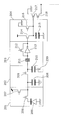
- FIG. 20 is a diagram illustrating an example of a circuit configuration of the pixel circuit according to the present embodiment.
- the pixel circuit of this embodiment includes a light receiving circuit 201, a counter circuit 202, a comparison circuit 203, a storage circuit 204, a light receiving element 205, a transfer transistor 206, a reset transistor 207, a charge storage capacitor 208, and a counter.
- the transistor 209, the counter capacitor 210, the DC cut capacitor 211, the clamp transistor 212, the inverter 213, the input transistor 214, the storage capacitor 215, the storage node reset transistor 216, the amplification transistor 217, and the selection transistor 218 are configured.
- 230 is an output permission signal.
- the distance measurement includes a period in which background light is detected and a threshold is set, and a period in which distance measurement is performed.
- the background light detection operation is performed by turning off the signal light from the light source. At this time, incident light to the distance measuring device 10 is only due to background light.
- the reset transistor 207 is turned on, and then the transfer transistor 206 is turned on to reset the light receiving element 205. Then, the transfer transistor 206, both from OFF the reset transistor 207 is ON the transfer transistor 206 only t a seconds. If light is incident on the t a seconds, it charges corresponding to is stored in the charge storage capacitor 208 through the transfer transistor 206. After t a seconds, the transfer transistor 206 is turned off, a voltage is applied to the gate of the counter transistor 209 (counter trigger), and the counter transistor 209 is turned on to transfer the charge to the counter capacitor 210.
- the counter trigger is turned off, that is, the counter transistor 209 is turned off, the reset transistor 207 is turned on, and the charge of the charge storage capacitor 208 is reset.
- the threshold setting signal of the comparison circuit 203 is turned ON, and this signal is applied to the clamp transistor 212, whereby the voltage of the counter capacitor 210 corresponding to the background light is stored as the voltage across the DC cut capacitor 211.
- the output permission signal is set to an arbitrary voltage E.
- the distance measurement operation is performed by turning on the light source.
- the following operation corresponds to an operation within one repetition period.
- the reset transistor 207 is turned on in advance to reset the charge in the charge storage capacitor 208.
- a signal light pulse is emitted.
- the transfer gate is turned on during the period represented by (Equation 3).
- ON counter trigger transfers charges generated by the receiving element 205 in the counter capacity 210. Repeat this process b times. Thereafter, the voltage of the output permission signal is changed to zero.
- the comparison circuit The state of the inverter 213 changes, and the input transistor 214 is turned ON. Since this threshold value can be adjusted by changing the voltage E at the lower end of the counter capacitor 210, it can be set to an appropriate value according to the use environment.
- the voltage value of the output permission signal is E in the background light detection period and 0 in the distance measurement period.
- the voltage value is not limited to this. For example, 0 in the background light detection period and ⁇ E in the distance measurement period.
- the setting value in the background light detection period may be set so that there is a difference between the setting value in the distance measurement period.
- a time signal (voltage) corresponding to the distance signal is applied to the drain of the input transistor 214.
- (1 + i / R) volts (R is an arbitrary integer) may be used.
- a voltage corresponding to the distance to the measurement object is stored in the storage capacitor 215 of each pixel. This signal is output during the distance signal output period.
- the selection transistor 218 is turned on. At this time, the voltage stored in the storage capacitor 215 is output by the amplification transistor 217. In reality, an offset voltage unique to the amplification transistor 217 is superimposed on this voltage.
- the storage node reset transistor 216 is turned ON to reset the voltage of the storage capacitor 215.
- the output voltage from the amplification transistor 217 after the storage node reset transistor 216 is turned off is read.
- a correlated double sampling (CDS) circuit or the like is provided in the subsequent stage of the readout line, and distance data is obtained by removing the offset voltage.
- the transfer transistor 206, the reset transistor 207, and the counter transistor 209 are turned on before exposure, and the photodiode 201, the charge storage capacitor 208, and the counter capacitor 210 are set to a reset voltage.
- the reset transistor 207 is turned off.
- the electrons photoelectrically converted by the photodiode 201 are accumulated in the parasitic capacitance and the charge storage capacitance 208 of the photodiode 201. This corresponds to the start of exposure, and the exposure times E 11 and E in FIG. 12, corresponding to the start time of the E 13.
- the time to turn OFF the reset transistor 207 By changing the time to turn OFF the reset transistor 207, it is possible to arbitrarily change the exposure start time, in the first repetition period in FIG. 2 (b), if OFF the reset transistor 207 at the start time of the exposure time E 11 well, in the second repetition period shown in FIG. 2 (b), it may be OFF reset transistor 207 in synchronization with the start of the exposure time E 12, the third repetition period of FIG. 2 (b), the exposure time E
- the reset transistor 207 may be turned off in synchronism with the start of No. 13 .
- this time is the time when the exposure ends. That is, it corresponds to the end time of the exposure times E 11 , E 12 , E 13 in FIG.
- the time a from the start of exposure to the end of exposure may be set to 2 l / nc. That is, the time from when the reset transistor 207 is turned off to when the transfer transistor 206 is turned off may be 2 l / nc.
- the start time and end time of the exposure times E 11 , E 12 , E 13 in the divided sections are determined by measuring the delay time with respect to the pulse emission.
- a method using a clock circuit can be considered.
- the exposure start time and the exposure end time can be determined by counting the number of clocks from the light pulse emission. Note that the method of synchronizing light emission and exposure is not limited to the above.
- the first period and the second period are measured in the first period or the second period while the measurement conditions are different.
- the distance may be measured in at least one of the period and the second period. That is, the control unit 103 sets a first measurement time range that is a time range corresponding to the first measurement distance range during the first period, and outputs the light to the light emitting unit 101 in the first measurement time range. Light is emitted, and the light receiving unit 102 is exposed. Furthermore, the control unit 103 sets a second measurement time range that is a time range corresponding to the second measurement distance range during the second period, and emits light to the light emitting unit 101 in the second measurement time range. And the light receiving unit 102 is exposed.
- the control unit 103 makes at least one measurement condition different between the first period and the second period. Then, the distance calculation unit 105 is based on the time from when the light emitted from the light emitting unit 101 is emitted in at least one of the first period and the second period to the time when the light receiving unit 102 receives the reflected light. What is necessary is just to calculate the distance from the distance measuring device 10 to the measuring object 60.
- the distance measuring device 10 may perform distance measurement a plurality of times, and may measure the distance by dividing the measurement section at one time.
- An example of the distance measurement operation sequence in this case is shown in FIG.
- FIG. 24 is a diagram illustrating an example of a distance measuring operation sequence of the distance measuring apparatus 10 according to the modification of the first embodiment. Since the same elements as those in FIG. 2 are given the same names, detailed description thereof is omitted.
- the control unit 103 of the distance measurement apparatus 10 is a time range corresponding to the first measurement distance range during the first period.
- a first measurement time range is set, and in the first measurement time range, emitted light is emitted from the light emitting unit 101, and the light receiving unit 102 is being exposed.
- the control unit 103 sets the second measurement time range, which is a time range corresponding to the second measurement distance range, to K ′ (K ′: a natural number of 2 or more) intervals during the second period.
- the portion may be exposed.
- the distance calculation unit 105 is based on the time from the time when the light emitted from the light emitting unit 101 is emitted during at least one of the first period and the second period to the time when the light receiving unit 102 receives the reflected light.
- the distance from the distance measuring device 10 to the measurement object 60 may be calculated.
- the distance measurement device 10 according to the present embodiment differs from the distance measurement device 10 according to the first embodiment in the operation contents of the control unit 103 and the distance calculation unit 105.
- the control unit 103 divides the first measurement time range into K sections (K: a natural number of 1 or more), the time for emitting light emitted from the light emitting unit 101, and the first measurement time range.
- K a natural number of 1 or more
- the light emitting unit 101 emits emitted light every first repetition period
- the light receiving unit 102 is exposed in at least one of the K intervals for each first repetition period.
- the control to be made inside is performed.
- the control unit 103 performs the second measurement distance range in the second period. To change. Then, the light receiving unit 102 is controlled using the second measurement distance range. More specifically, in this case, the control unit 103 performs the second measurement time corresponding to the second measurement distance range including the region not included in the measurement distance range used in the first period in the second period. The light receiving unit 102 is controlled using the range.
- control unit 103 confirms that the light receiving unit 102 receives reflected light and the measurement object 60 exists in the Lth section (L: natural number equal to or less than K) among the K sections.
- the control unit 103 includes K ′ (K ′: K ′) second measurement time ranges that include the L period and are shorter than the first measurement time range used in the first period. 2), and the second repetition period including the time for emitting the light emitted from the light emitting unit 101 and the second measurement time range is repeated K ′ times, and the K ′ is repeated every second repetition period. Control is performed so that the light receiving unit 102 is exposed during at least one of the intervals.
- the distance calculation unit 105 calculates the distance from the distance measuring device 10 to the measurement object 60 based on the time from the time when the light emitted from the light emitting unit 101 is emitted in the second period to the time when the light receiving unit 102 receives the light. What is necessary is just to calculate.
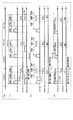
- FIG. 3 is a diagram showing an example of a distance measuring operation sequence of the distance measuring apparatus 10 according to the present embodiment. Elements similar to those in FIG. 2 are denoted by the same reference numerals, and detailed description thereof is omitted.
- FIG. 3A is similar to FIG. 2A of Embodiment 1 in that the distance measurement operation is performed under different measurement conditions in the first period and the second period.
- the second period is different in that the measurement condition is determined according to the result of the distance measurement operation in the first period.
- FIG. 3B shows a case where the measurement object 60 cannot be detected in the first period.
- the other operations are the same as those described with reference to FIG. 2B, and a description thereof is omitted here.
- An example in which a distance measurement operation is performed using a measurement distance range is shown. More specifically, in the second period, three repetition periods including three divided sections (section 31, section 32, section 33) when N is 3 and the time during which the light emitting unit 101 emits pulsed light are repeated three times. A repeated example is shown.
- the light emitting unit 101 emits pulsed light (P 21 , P 22 , P 23 ) for each repetition period, and the light receiving unit 102 includes at least a divided section (section 31, section 32, section 33) for each repetition period. One section is being exposed.
- the second measurement time range (the time of the sections 31 to 33) that does not include the first measurement time range (the time range of the sections 11 to 13) in which the ranging operation is performed in the first period. Range), but may include a measurement time range including the first measurement time range in which the distance measurement operation is performed in the first period.
- the measurement time range of the second period may be arbitrarily determined.
- the number of periods may be any number of times, not limited to the first period and the second period. In this case, a method of sequentially increasing the measurement distance range can be considered.
- FIG. 4 is a diagram showing another example of the distance measuring operation sequence of the distance measuring apparatus 10 according to the present embodiment. Elements similar to those in FIGS. 2 and 3 are denoted by the same reference numerals, and detailed description thereof is omitted.
- FIG. 4B shows a case where the measurement object 60 is detected in the first period.
- the other operations are the same as those described with reference to FIG. 2B, and a description thereof is omitted here.
- the second period shown in FIG. 4C in the divided section (section 13) in which the measurement object 60 is detected in the first period shown in FIG. 4B, or in the vicinity of the divided section.
- An example in which the distance measuring operation is performed using the limited second measurement time range is shown. More specifically, in the second period, a repetition period including three divided sections (section 41, section 42, section 43) when N is 3 and a time during which the light emitting unit 101 emits pulsed light is repeated three times. A repeated example is shown. Then, the light emitting unit 101 emits pulsed light (P 21, P 22, P 23) for each repetition period, the light receiving unit 102, at least of the divided sections each repetition period (section 41, section 42, section 43) An example of exposure during one section is shown.
- the control unit 103 determines the second measurement time range according to the result of the distance measurement operation in the first period. Then, the control unit 103 divides the second measurement time range into a plurality of sections (divided sections), and performs a ranging operation for each divided section by repeating the repetition period a plurality of times.
- the control unit 103 performs ranging in the second period.
- the second measurement time range in which the operation is performed is matched with the divided section i in which the measurement object 60 is detected in the first period.
- the method for dividing the first measurement time range and the second measurement time range is not limited to an equal interval, and is arbitrary.
- the measurement time range may be narrowed sequentially with reference to the result of the previous period to improve the measurement resolution.
- FIG. 5 is a diagram illustrating another example of the distance measuring operation sequence of the distance measuring apparatus 10 according to the present embodiment. Elements similar to those in FIG. 4 are denoted by the same reference numerals, and detailed description thereof is omitted.
- the measurement time range is preferably the same as the section in which the measurement object is detected in the previous period, but a time range wider than the divided section may be selected.
- the measurement time range does not necessarily need to be continuously narrowed.
- a period for performing low-resolution period measurement with a wide measurement time range may be added between measurements with a narrow measurement time range. The advantage of this method is that even when an object suddenly enters outside the measurement time range of the distance measuring device 10, the distance of the measurement object can be measured by measurement with a wide measurement time range.
- the exposure time width is less than or equal to the optical pulse width, and change the exposure start time by a step size smaller than the optical pulse width.
- the distance from the object 60 to be measured is the exposure start time at which the intensity of the reflected light is maximized.
- a circuit shown in FIG. 10 described later is preferably used.
- the light receiving unit 102 when configured using an image sensor, a two-dimensional distance data group can be configured, and a distance image can be obtained.
- a plurality of measurement objects (measurement objects 60) are detected by one distance measurement.
- measurement under the same conditions as the measurement conditions in the first period May be performed.
- humans and animals perform measurements with high distance resolution, but do not perform measurements on houses, walls, signs, etc. The limiting method is not limited to the above.
- the light receiving unit 102 has a plurality of distance measuring devices arranged two-dimensionally and can output a distance image
- the measurement results of the plurality of distance measuring devices are integrated to determine the number of incident photons. It is also possible to use a method of counting the sum, average, variance, etc. and determining that a photon has been detected when a significant difference from the background light is recognized. The measurement flow in this case will be described below with reference to the drawings.
- 6A, 6B, and 6C are diagrams showing another example of the distance measuring operation sequence of the distance measuring apparatus 10 according to the present embodiment.
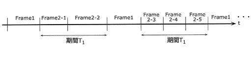
- FIG. 6A shows a case in which a distance measurement operation with a low measurement resolution is performed in the first period, and then a second period having a higher measurement resolution than the first period is performed n times.
- the distance measurement device 10 performs a distance measurement operation with a low measurement resolution in the first period, and the objects 1, 2, 3,..., N are distances z1, z2, z3,. Assume that zn is calculated.
- the distance measuring device 10 has a second measurement resolution higher than that of the first period for each of the objects 1, 2, 3,..., N at the distances z1, z2, z3,.
- the ranging operation is performed in the ⁇ 1 period, the 2-1 period,..., The 2-nth frame.
- the progress of the period is not limited to the case shown in FIG. 6A.
- the distance measurement operation may be performed by alternately progressing a first period with a low measurement resolution and a second period with a high measurement resolution.
- the ratio of the first period with a high measurement resolution and the second period with a low measurement resolution is set to 1: 1, and an arbitrary ratio such as 1: 2 is used.
- the period may be advanced.
- time for performing a plurality of second periods may be set in advance, such as repeatedly performing a second period with high measurement resolution. Needless to say, the progress of the period is not limited to these examples.
- Embodiment 3 In the first and second embodiments, the case where the distance measuring device 10 and the measuring object 60 move such as movement is not mentioned. Therefore, in the present embodiment, the distance measuring device 10 or the measuring object 60 is moved. In the case of being present, the difference from Embodiments 1 and 2 will be mainly described.
- the distance measurement device 10 according to the present embodiment differs from the distance measurement device 10 according to the first and second embodiments in the operation contents of the control unit 103 and the distance calculation unit 105.
- the control unit 103 receives the reflected light and the measurement object 60 has an Nth section (N: K ′ (M) or less) among the K ′ (M) sections. Suppose that it exists in natural number).
- the control unit 103 includes O (O) third measurement time ranges including the N period and equal to or less than the second measurement time range used in the second period. : A natural number greater than or equal to 2), and the third repetition period including the time for emitting the light emitted from the light emitting unit 101 and the third measurement time range is repeated O times, and the O number of times for each third repetition period Control is performed so that the light receiving unit 102 is exposed during at least one of the intervals.
- the distance calculation unit 105 calculates the distance from the distance measuring device 10 to the measurement object 60 based on the time from the time when the light emitted from the light emitting unit 101 is emitted in the third period to the time when the light receiving unit 102 receives the light. What is necessary is just to calculate.
- the distance calculation is performed.
- the unit 105 may obtain a distance difference that is a difference between the distance calculated in the third period and the distance calculated in the second period. Then, the distance calculation unit 105 calculates the ratio between the obtained distance difference and the time from the start time of the Nth section in the second period to the start time of the Pth section in the third period. You may obtain
- the start time of the Nth section and the start time of the Pth section are used, characteristic times of the Nth section and the Pth section may be used.
- the end time of the Nth section and the Pth section It may be the end time of the section.
- the control unit 103 adds the distance value obtained by multiplying the speed by the time from the start time of the third period to the start time of the fourth period to the start time of the fourth period to the distance calculated in the third period.
- the distance range of the measurement object 60 in the fourth period can be predicted. Therefore, in the fourth period, the control unit 103 determines a fourth measurement time range that includes a measurement time range corresponding to the predicted distance range and is shorter than the third measurement time range.
- the fourth repetition period including the time for emitting the light emitted from the light-emitting unit 101 and the fourth measurement time range is repeated a plurality of times, and at least one of the plurality of sections for each fourth repetition period. Control is performed so that the light receiving unit 102 is exposed during the interval.
- FIG. 7 is a diagram showing an example of a distance measuring operation sequence of the distance measuring apparatus 10 according to the present embodiment. Elements similar to those in FIG. 4 are denoted by the same reference numerals, and detailed description thereof is omitted.
- FIG. 7A four distance measuring operations in the first period, the second period, the third period, and the fourth period are performed as one set. . 7B and 7C are the same as FIG. 4B and FIG. 4C, and thus the description thereof is omitted.
- distance measurement is performed with a distance resolution equivalent to that of the second period or a distance resolution higher than that of the second period. Since the details of the operation are as described in FIG. 4C, description thereof is omitted here.
- the distance to the measurement object 60 obtained by the control unit 103 in the second period is z1, and the distance to the measurement object 60 obtained in the third period is z2. Further, the time from the time when the measurement object 60 is detected in the second period to the time when the measurement object 60 is detected in the third period is denoted by ⁇ t1. In this case, the control unit 103 can calculate the speed v1 in the distance direction of the measurement object 60 using (Expression 6).
- the control unit 103 may obtain the velocity v2 in the distance direction of the measurement object 60 from the third period to the fourth period. Using the time ⁇ t2 from the time when the measurement object 60 is detected in the period of time to the time when the measurement object 60 is detected in the fourth period and the speeds v1 and v2, the acceleration a 1 of the measurement object 60 is expressed by It may be calculated from 7).
- the control unit 103 uses the velocity v1 of the measurement object 60 obtained in the third period shown in FIG.
- the distance (position) of the measurement object 60 at is predicted, and a fourth measurement distance range including the predicted distance (position) is determined.
- the distance measuring apparatus 10 can divide the fourth measurement distance range including the distance (position) where the measurement object 60 exists in the fourth period to increase the measurement resolution, thereby further improving the measurement accuracy. can do.
- the distance z2 and speed v1 of the measurement object 60 obtained in the third period, and the time from the time representative of the third period to the time representative of the fourth period are denoted by ⁇ t2.
- the control unit 103 can predict the position of the measurement object 60 existing in the fourth period using (Equation 8).
- control unit 103 can perform the distance measurement operation only in the vicinity of the distance where the measurement object 60 is predicted to exist in the fourth period, and the measurement object with higher resolution and fewer measurement times.
- the distance to the object 60 can be calculated.
- an image sensor that is an element in which light receiving elements are arranged in a two-dimensional array is used in the light receiving unit 102, and if necessary, an optical system is mounted to measure two-dimensional distance data, that is, a distance image.
- it can be used for recognizing people and animals.
- the distance measuring device 10 is mounted on a vehicle running on a general road at a speed of 60 km / h to recognize a person or an animal, the following performance is required.
- the measurement resolution requires about 0.1 m, which is half the thickness.
- the distance range corresponding to one divided section is 0.1 m
- the number of divided sections in the measurement time range is a distance variation. It is necessary to make it at least 6 or more so as to include 0.6 m / min. Since the stop distance of a 60 km / h car is about 35 m, in order to recognize a person and stop with a margin, it is necessary to capture a distance image about 100 m ahead of this three times.
- the laser light source used for the light emitting unit 101 is considered to be equivalent to class 1, and the intensity is about 1 mW and the irradiation angle is 10 °.
- the resolution of the image sensor in the horizontal and vertical directions is required to be about 0.1 m. Therefore, the focal length of the lens is designed to achieve this resolution, and the lens radius is set to about 1 cm.
- the reflectance of the measurement object 60 is 0.1.
- the wavelength of the light pulse emitted from the laser light source is 860 nm
- the number of photons of the light pulse is about 4 ⁇ 10 15 per second, and the reflected light that is reflected back to the measuring object 60 returns approximately per second. It is calculated as 1 ⁇ 10 3 pieces.
- the quantum efficiency of the image sensor is set to 60%, it takes about 2 ms to detect the return of one photon to the sensor. Therefore, if the measurement is performed 6 times, the measurement time of 12 ms is taken. Take it. Since the frame rate of a general moving image is approximately 30 fps, one frame needs to be 30 ms or less. In the conventional distance measuring operation described above, it is not possible to recognize three or more people and animals and output them as images. Is possible.
- the measurement method of the present embodiment there is substantially no lower limit of the number of divided sections in each period, and the measurement object that is in motion can be assured with one measurement. It can also be captured.
- the measurement time is a maximum of 1/6 times, so it is possible to capture about 10 measurement objects with high distance resolution. Therefore, for example, an effect can be expected in applications such as remote object recognition in in-vehicle applications.
- a distance measuring device is arranged in a two-dimensional array in the light receiving unit 102, and if necessary, a two-dimensional image of distance measuring data can be measured by constructing an optical system using a lens or the like.
- a distance measuring device having a simple configuration may be used.
- a light receiving element that does not include an optical system is called an image sensor, and each element that can output a measurement result independently is called a pixel.
- FIG. 12 is a diagram for explaining the relationship between the position between the image sensor 31 and the object 33 according to the present embodiment and the position at which the point P in the measurement object is imaged in the image sensor 31. .
- Equation 9 can be used to predict the region in the image sensor where the measurement target appears in the next frame.
- the area on the image sensor where the image recognition process is performed can be limited to the vicinity of the measurement target, and the time required for the image recognition process can be shortened.
- the difference ( ⁇ x, ⁇ y) between the vertical and horizontal positions (x, y) of the measurement object 60 in the image is taken, and the difference ⁇ t between the two measurements, which is the difference between the two measurements.
- the velocity (v x , v y ) ( ⁇ x / ⁇ t, ⁇ y / ⁇ t) of the measuring object 60 in the screen is obtained, so that the measuring object 60 is measured at the next distance measurement. May be predicted to determine an area on which image recognition processing is performed.
- the speed of the distance measuring device 10 can be obtained by the speed measurement shown in the present embodiment.
- Register a stationary object in advance in the camera system examples include, but are not limited to, walls, buildings, and road signs.
- this velocity vst is the relative velocity between the stationary object and the distance measuring device 10, and the absolute velocity of the stationary object is 0 m / s. Therefore, as shown in (Equation 10), the relative velocity vst is The speed multiplied by ⁇ 1 is the moving speed V of the distance measuring device.
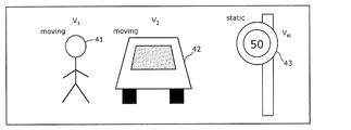
- FIG. 13 is an example of a distance image measured by the distance measuring device 10.
- FIG. 13 shows an object 41 that is, for example, a person, an object 42 that is, for example, a car, and an object 43 that is, for example, a sign.
- the distance measuring device 10 including the image sensor 31 is a sign (object 43) that is stopped from the three measurement objects 60 shown in FIG. 12, that is, a person (object 41), a car (object 42), and a sign (object 43).
- the speed of the distance measuring device 10 can be obtained from the relative speed.
- the distance measuring device 10 when the distance measuring device 10 according to the present embodiment is used for in-vehicle applications, it is necessary to change the measurement conditions depending on the vehicle speed. For example, when the speed of the car is high, it is desired to measure the distance in the distance, but when the speed is low, it is desired to measure the distance only in the near distance. Therefore, the distance measurement device 10 itself recognizes its own speed, so that the distance measurement can be performed sequentially while feeding back the measurement result and changing the measurement conditions.
- the speedometer Even if the camera system is operating normally with the speedometer, if the speedometer does not operate correctly, such as when slipping or idling, the speed determined by the distance measuring device 10 is provided to the speedometer. The correct vehicle speed can be displayed.
- the distance measuring device 10 according to the present embodiment is different from the distance measuring device 10 according to the first embodiment in the operation content of the control unit 103.
- the control unit 103 provides a second repetition period that is shorter than the first measurement time range and is the same as the time width of the section in which the measurement target 60 is detected among the K sections.
- the light emitting unit 101 emits emitted light at the same cycle as the second repetition period, and the light receiving unit 102 is provided in one of the divided sections obtained by dividing the second repetition period into M (M: natural number of 2 or more) sections. Is controlled during exposure.
- the lower limit of the time width of the repetition period is defined as a time that sufficiently attenuates the reflected light of a certain repetition period so that it is not erroneously detected in another repetition period. This regulation is not performed in the embodiment.
- the control unit 103 causes the distance calculation unit 105 to measure (calculate) the distance of the measurement object 60 by performing AND processing on the results of the first period and the second period.
- the distance is determined with the resolution represented by (Equation 4).
- the distance resolution is also 1 / M.
- the second period since it is assumed that light is emitted with a light emission period shorter than the decay time of the light pulse, the correspondence between the light emission pulse and the light reception pulse cannot be determined 1: 1, and an integer of the light emission period Td . It is necessary to consider periodic wrapping at double. That is, when pulse light is detected in the j-th section among the M sections, the distance data is represented by the following (Equation 11), where T d is the time width of the repetition period.
- k is an unknown integer of 0 or more
- kT d corresponds to the aliasing components. Since (Expression 4) can uniquely determine the distance with the resolution of T d , the unknown integer k in the result of (Expression 11) can be determined uniquely, and the position of the measurement target with the resolution T d / M. Can be determined.
- a light emission and exposure driving method (ranging operation) in distance measurement of the distance measuring apparatus 10 according to the present embodiment configured as described above will be described.
- FIG. 8 and 9 are diagrams showing an example of a distance measuring operation sequence of the distance measuring apparatus 10 according to the present embodiment. Elements similar to those in FIG. 2 are denoted by the same reference numerals, and detailed description thereof is omitted.
- the other operations are the same as those described with reference to FIG. 2B, and a description thereof is omitted here.
- the control unit 103 has the same period of time T d as the first divided section (section 12, section 13, section 14) of the first measurement time range.
- the light emitting unit 101 emits a light pulse.
- the control unit 103 performs control so that the light receiving unit 102 is being exposed in one section (second divided section) obtained by dividing the period into three.
- FIG. 8C shows an example of driving for performing integration, and averaging in the figure corresponds to one integration. Of course, only one light pulse may be emitted for one section without performing integration. When integrating, the distance is calculated using the average value or the sum.
- FIG. 8C shows an example in which reflected light returns to the second section in the second period.
- the present driving method has an advantage that the distance data can be determined by performing the measurement in the second period without referring to the distance data in the first period and performing arithmetic processing in the subsequent stage. . Since it is unnecessary to determine whether or not the measurement target is detected and to perform recognition processing, the measurement time can be shortened.
- the measurement time can be shortened by eliminating the time required for the recognition process.
- the measurement method described in this embodiment has the following two advantages. 1. 1. Increase the efficiency of long distance measurement; This is high-precision measurement of a plurality of objects in distance image measurement.
- an example will be described.
- the efficiency improvement of long distance measurement will be described. That is, at the time of measurement at a distant place, the number of photons reflected and returned from the measurement object decreases, so that the number of integrations increases. Therefore, it is important to shorten the cycle of the light emission pulse and increase the number of integrations.
- the probability that one photon caused by one light pulse returns to the light receiving unit and undergoes photoelectric conversion is less than 1/2000, so that an integration of about 2000 times is required at a minimum.
- the time required for the light pulse to be reflected from the measurement object at a distance of 250 m and returning to the light receiving unit is approximately 1.6 ⁇ s, so the lower limit of the repetition time is defined as 1.6 ⁇ s, Even if the light pulse is emitted 2000 times, it takes 4 ms to measure in one section.
- the step size of the measurement distance range is set to 10 m in the first period
- the cycle of emitting the light pulse in the second period is Since it is approximately 0.06 ⁇ s at 1/25 times, even if the pulse light emission is performed 2000 times, it becomes 0.12 ms. This is a negligible time of 1/400 times the time of 30 ms for one frame in the case of a general frame rate of 30 fps for moving images.
- the distance image here refers to a two-dimensional distance data group output from a distance measuring device arranged in a two-dimensional array and, if necessary, a measuring device system having an optical system such as a lens.
- the timing for detecting reflected light at the corresponding pixel differs depending on the distance of each measurement object. Need to be implemented. However, in the present embodiment, different results corresponding to the distance to be measured can be obtained with the same exposure sequence for all pixels. This will be described with reference to FIG.
- the sequence of emitted light, reflected light, and exposure is shown.
- the emitted light is the same, and the exposure timing is the same for both pixel A and pixel B.
- the pixel A detects light in the third interval
- the pixel B detects light in the second interval
- the pixel A detects light in the second interval
- the pixel B detects light in the first interval. Is detected.
- the first period and the second period may be performed in any order.
- the third period, the fourth period,... May be added, and the operation for sequentially increasing the resolution may be performed.
- the first exposure in the second period starts from the time when the first pulse light is expected to be surely returned. It is desirable to do.
- the reflected light R 31 of the light pulse P 31 one-time one-shot eyes the exposure time E 31 is not returned, the exposure time E 31 Is a useless exposure and, out of the four integrations, the light should be detected four times, but only three times are detected, so the possibility of detection omission increases.
- the first exposure start time in the second period is set to be after the start time of the last section of the first measurement time range in the first period, Detection omission can be prevented. That is, the first-th exposure of the second period may be started from the exposure time E 33.
- the number of pulse emission times is larger than the number of exposure times, and thus there are disadvantages such as an increase in power consumption and a long measurement time.
- pulse emission of 1000 times or more is necessary.
- an increase in the number of pulse emission is equal to the number of section divisions of the first measurement. Since it is about 10 times at most, it is only an increase of 1%.
- the distance measuring device 10 according to the present embodiment is different in the operation content of the control unit 103 from the distance measuring device 10 according to the first to fourth embodiments.
- the following description will focus on the differences from Embodiments 1 to 4.
- control unit 103 divides the measurement time range into K sections (K: a natural number of 1 or more) in the first period and the second period, and the time for emitting the light emitted from the light emitting unit 101
- K a natural number of 1 or more
- control unit 103 causes the light emitting unit 101 to emit emitted light with a narrow pulse width that is shorter than half of the interval for each start time of the repetition period, and K intervals for each repetition period. Control is performed so that the light receiving unit 102 is exposed during at least one section.
- the control unit 103 causes the light emitting unit 101 to emit emitted light with a wide pulse width that is half the time of each of the K intervals of the repetition period. Then, in each of the K sections of the repetition period, the control unit 103 performs first exposure period control that causes the light receiving unit 102 to be exposed during the first time that is a half time of the section for each start time of the section. And a second exposure period control in which the light receiving unit 102 is exposed during the first time from the time when the first time has elapsed from the start time of the section.
- the first exposure period corresponds to the following A exposure period
- the second exposure period corresponds to the following B exposure period.
- FIG. 10 is a diagram showing an example of a distance measuring operation sequence of the distance measuring apparatus 10 according to the present embodiment. Elements similar to those in FIG. 2 are denoted by the same reference numerals, and detailed description thereof is omitted.
- the distance of the measuring object 60 is measured using the same distance measuring method as in FIG. 2A of the first embodiment. Since it is the same as (a) in FIG. 2 except that the reflected light returns in the section 12 and there is no waiting time between the repetition periods, detailed description thereof is omitted here. . Note that there may be a waiting time between the repetition periods in the first period.
- the light emitting unit 101 alternately repeats light emission and quenching with the same time width (first time), and the light receiving unit 102 performs light emission and quenching of the light emitting unit 101, respectively.
- Light reception is performed in two different exposure sequences that are synchronized.
- the control unit 103 calculates the distance between the measurement object 60 and the distance measuring device 10 from the ratio of the intensity of the reflected light obtained in each of these exposure sequences.
- the control unit 103 controls the light receiving unit 102 to perform A exposure (first exposure sequence) performed in synchronization with light emission of the light emitting unit 101 and B exposure (second exposure sequence) performed in synchronization with extinction.
- control unit 103 stores the light intensity SA of the reflected light detected by the light receiving unit 102 during the A exposure and the light intensity SB of the reflected light detected by the light receiving unit 102 during the B exposure, respectively, in a memory (not shown). .
- the A exposure and the B exposure may be performed using different pixels or the same pixel.
- the distance to the measurement object 60 is z 4
- the time when the reflected light returns to the distance measuring device 10 is ⁇ from the light emission
- the time ⁇ (2z 4 / c) ⁇ first time when the reflected light returns first.
- T0 the time width of the reflected light received during the A exposure period
- T0 ⁇ the time width of the reflected light received during the B exposure period
- T0 ⁇ (T0 ⁇ ) ⁇ .
- the ratio (intensity ratio) between the light intensity SA of the reflected light detected by the light receiving unit 102 and the light intensity SB of the reflected light detected by the light receiving unit 102 during B exposure can be expressed by (Equation 12).
- the distance of the measuring object 60 and the distance measuring apparatus 10 can be represented by (Formula 13).
- the distance measuring device can be obtained by using the signal intensity ratio (SA ⁇ SB) / (SA + SB) of the reflected light.
- SA ⁇ SB signal intensity ratio
- SA + SB signal intensity ratio
- the distance from 10 to the measurement object 60 can be obtained as a continuous value.
- Such a second period is advantageous over the first period in which the distance can be obtained only with the resolution determined by the time width of the divided section.
- n in ⁇ + 2nT0 can be determined.
- the distance to be measured can be obtained as a continuous value in two measurements.
- the result of the first period and the result of the second period are AND-processed (AND operation process) without feeding back the result of the first period.
- the distance from the measuring device 10 to the measuring object 60 can be uniquely determined.
- the recognition processing takes about several milliseconds, which may be rate-limiting to the frame rate.
- the measurement time can be shortened because there is no recognition processing.
- the measurement of the second period may be performed by feeding back the result of the first period.
- it is not necessary to repeat light pulse emission and quenching as shown in FIG. A exposure in which exposure is performed for T0 from the start time of the divided section in which reflected light is detected in the first period and B exposure in which exposure is performed for T0 from the end of A exposure may be performed only once.
- the number of exposures can be reduced, and generation of pulse noise and thermal noise due to background light can be prevented, so that erroneous detection of reflected light can be prevented.
- an avalanche photodiode may be used for the light receiving unit 102.
- the Geiger mode in which a voltage higher than the breakdown voltage is applied, it is possible to multiply the optical signal from a single photon to a saturation value, and the sensitivity of the light receiving unit 102 is increased to a single photon. It can be increased to a detectable level.
- the Geiger mode is suitable for use in detecting the presence or absence of light because the photodiode is easily saturated and noise is also amplified, but is not suitable for use in obtaining the absolute value of the amount of light.
- the normal mode in which a voltage equal to or lower than the breakdown voltage is applied, it can be used as a normal photodiode and can also be used for obtaining an absolute value of signal intensity.
- the measurement since it is only necessary to determine whether or not light returns during the exposure period in the first period, measurement may be performed in the Geiger mode. As a result, remote measurement with a small amount of light returning can be performed with a small number of integrations.
- the measurement in the second period, the measurement may be performed in the normal mode.
- the APD can switch the light detection characteristic only by changing the applied voltage, a driving method suitable for each measurement method in the first period and the second period can be realized by a single device. The distance of the measurement object 60 can be obtained as a continuous value while detecting low-intensity light with high sensitivity.
- Patent Document 2 may be used as the pixel circuit in this case.
- this circuit is only used for measurement similar to the measurement in the second period, but by using this circuit, the measurement in the first period can be efficiently performed. Will be able to.
- FIG. 22 shows a pixel circuit configuration and an exposure sequence.
- the pixel circuit has two floating diffusion regions (FD1, FD2).
- the SA signal values shown in (Expression 12), (Expression 13), and (Expression 9) are stored in one (for example, FD1)
- the SB signal value is stored in the other (for example, FD2).
- the distance values of (Expression 13) and (Expression 9) can be measured by taking the sum and difference at the subsequent stage.
- the first period as shown in FIG. 22 (b), it is possible to measure two different divided sections during the same repetition period by making the exposure timing different between FD1 and FD2. Furthermore, if signal difference processing is performed in the subsequent stage, it is possible to easily determine which stray diffusion capacitor has been charged by simply looking at the sign of the signal. For example, if a process for calculating the signal amount of FD1 ⁇ the signal amount of FD2 is provided in the subsequent stage, if the sign of the signal is positive, it can be understood that the reflected light has returned to the section where exposure has been performed with FD1, and the signal If the sign is negative, it can be seen that the reflected light has returned to the section where exposure has been performed with FD1. By using this method, the number of pulse emission can be reduced to half, and the measurement time in the first period is halved.
- the distance measuring apparatus 10 includes a pixel circuit that can acquire distance data in the first period and can acquire luminance data in the second period. That is, the pixel circuit of this embodiment includes both a distance measurement circuit that acquires distance data and a luminance measurement circuit that acquires luminance data.
- An example of the pixel circuit of the present embodiment has a configuration as shown in FIG. 11, and both distance image data and luminance image data can be measured with the same circuit configuration. It is also possible to perform distance measurement and luminance measurement simultaneously.
- FIG. 11 is a diagram illustrating an example of a circuit configuration of the pixel circuit according to the present embodiment.
- the pixel circuit of this embodiment includes a light receiving circuit 201, a counter circuit 202, a comparison circuit 203, a storage circuit 204, a light receiving element 205, a transfer transistor 206, a reset transistor 207, a charge storage capacitor 208, and a counter.
- 230 is an output permission signal.
- the configuration is the same as a pixel circuit of a normal image sensor.
- the reset transistor 207 from the ON first, then turn ON the transfer gate voltage, after resetting the light-receiving element 205, and OFF the reset transistor 207, between t a, Doing receiving, transfer transistor 206 charges corresponding to it The charge is stored in the charge storage capacitor 208. After t a seconds, when the transfer transistor 206 is turned off and the luminance image selection transistor 220 is turned on, the output voltage from the luminance image amplification transistor 219 is read to obtain a signal. At this time, it is desirable to provide a CDS circuit in the subsequent stage and remove the offset voltage to obtain a luminance signal. In such a circuit configuration, both distance and luminance can be obtained with a single circuit configuration.
- a two-dimensional image of distance measurement data is constructed by constructing an optical system using an image sensor in which distance measuring devices are arranged in a two-dimensional array in the light receiving unit 102 and, if necessary, a lens or the like. You may use the solid-state imaging device made into the structure which can measure.
- the distance data output by a plurality of pixels is processed, arranged in a two-dimensional form, the distance image output by imaging, and the luminance data output by a plurality of pixels are processed, and arranged in a two-dimensional form. Then, an image such as a luminance image output as an image can be obtained.
- the type of image data to be acquired is not limited to the distance and the luminance.
- a method of providing a filter that blocks or transmits light of a specific frequency on the front surface of the light receiving unit 102 is also available.
- frequency information may be obtained.
- the order of acquisition of the luminance image and the distance image does not limit the scope of the right of the present application.
- the method of alternately repeating the luminance image measurement and the distance image measurement for example, the first in the first embodiment Luminance measurement is performed before or after the distance measurement is performed, or after the distance measurement of the period, the luminance measurement is performed, then the second period measurement is performed, and then the luminance measurement is performed. Possible ways to do this.
- the ratio of the number of times of distance measurement and luminance measurement may be set at an arbitrary ratio.
- the measurement object 60 can be recognized by a method such as recognition processing of a distance image and a luminance image at a later stage.
- the efficiency of the recognition process can be improved by combining the distance image and the luminance image.
- the distance measuring apparatus 10 according to the present embodiment first performs recognition processing on the distance image to narrow down the boundary of the measurement object 60.
- the distance measurement apparatus 10 according to the present embodiment performs the recognition process of the luminance image, but performs the recognition process again in an area corresponding to the inside of the boundary of the measurement object 60 narrowed down by the distance image.
- the distance measuring device 10 of the present embodiment can perform image recognition more efficiently.
- recognition processing can be performed complementarily with the distance image and the luminance image.
- the distance difference is less than or equal to the resolution of the distance measurement device
- the shape of each of the two measurement objects 60 cannot be recognized separately in the distance image. Examples are the boundaries between people and the ground, and animals that are near walls.
- the difference in reflectance between the two measurement objects 60 can be identified using the luminance image as in this embodiment, and the two measurement objects 60 can be recognized separately.
- the two measurement objects 60 can be recognized separately.
- an image sensor and, if necessary, an optical system such as a lens are used for the light receiving unit 102, and a solid-state imaging device that can measure a two-dimensional image of distance measurement data is used. It is also possible to obtain a distance image in which distance data is two-dimensionally arranged and a luminance image in which luminance data is two-dimensionally arranged. Moreover, it is good also as a structure which can recognize the measuring object 60 by methods, such as recognition processing of a distance image and a brightness
- the exposure timing is set the same for all pixels, but exposure is performed at different timings for each pixel. May be.
- Example 1 14A and 14B are schematic diagrams for explaining the exposure sequence of the distance measuring apparatus 10 according to the present embodiment.
- FIG. 14A is a schematic diagram illustrating an example of an image including the measurement target 60 imaged by the distance measuring device 10, and shows an object 41 at a distance z1, an object 42 at a distance z2, and an object 43 at a distance z3. Has been.
- FIG. 14A (b) and FIG. 14B (c) show driving when distance measurement is performed with the measurement range limited to 43.
- the measurement target objects 41, 42, and 43 exist at different positions in the distance image.
- a distance measurement device that detects the measurement target object 41 is called a pixel 1
- an exposure sequence is Exposure 1
- the measurement target object A distance measuring device that detects 42 is referred to as pixel 2
- the exposure sequence is called Exposure 2
- a distance measuring device that detects the object 43 to be measured is called pixel 3
- the exposure sequence is shown as Exposure 3.
- FIG. 14B (c) as described in FIG. 4C of the second embodiment and FIGS. 6A to 6C, the operation of performing distance measurement by limiting the measurement range in the vicinity of the detected measurement object is performed.
- the measurement is repeated for all the objects 41, 42, and 43 that are measurement objects.
- the pixel 2 that detected the object 42 to be measured in the first period is exposed during exposure, and within the first measurement time range,
- the pixel 3 having detected 43 is caused to be exposed.
- the light receiving unit 102 has a plurality of two-dimensionally arranged pixels that can receive light, and the light receiving unit 102 is divided into a plurality of regions. Has been.
- each pixel belongs to one of a plurality of regions.
- the control unit 103 divides the first measurement time range into K sections (K: a natural number of 1 or more) (first division period), the time for emitting the light emitted from the light emitting unit 101, and The repetition period including the first measurement time range is repeated K times (first repetition period).
- the control unit 103 causes the light emitting unit 101 to emit emitted light at each start time of the repetition period, and includes all of the plurality of areas in the area in each of the K sections of the repetition period. Control is performed to cause all pixels to be exposed during exposure.
- the second measurement time range is divided into L sections (L: a natural number equal to or greater than 1), and the repetition period including the time for emitting the light emitted from the light emitting unit 101 and the measurement time range is repeated L times.
- the control unit 103 performs control to cause the light emitting unit 101 to emit emitted light at each start time of the repetition period and to perform exposure of one of the plurality of regions in each of the L sections of the repetition period.
- the control unit 103 performs control for causing each of the plurality of regions to be different during exposure in the different second divided section.
- the control unit 103 performs control to cause a different area for each of the plurality of areas to be performed during exposure in different sections of the K sections of the repetition period.
- the control unit 103 has a plurality of objects 41, 42, and 43, which are measurement objects, by the light receiving unit 102 receiving a plurality of reflected lights, and among the K sections. Suppose that it is confirmed that it exists in a different section. In this case, the control unit 103 sets different measurement distance ranges for each of the plurality of regions in the second period, and sets the second measurement time range to K ′ sections according to the set different measurement distance ranges. What is necessary is just to divide. Thereby, it is possible to determine the measurement range for each of the plurality of pixels (regions) and measure the distance.
- FIGS. 15, 16, and 17 ⁇ / b> A are diagrams illustrating an example of an image sensor included in the light receiving unit 102 according to the present embodiment.
- FIG. 17B is a diagram illustrating an example of a control circuit of the image sensor in FIG. 17A.
- the pixel array 102a of the image sensor is divided into small areas of vertical N rows and horizontal M columns (N and M are natural numbers).
- Each of the small partition areas includes one or a plurality of pixels.
- a corresponding exposure gate driver is provided in each row and column of the small partition area and operates independently.
- N row pulse power sources for exposure and M column pulse power sources are connected to correspond to each of vertical N rows and horizontal M columns in the small partition area so that they can be operated independently.
- the row pulse power supply is turned on, the row selection transistor 1301 is turned on.
- the column pulse power supply is turned on, the column selection transistor 1302 is turned on, so that both the row selection transistor 1301 and the column selection transistor 1302 are turned on. Only, the power supply voltage 1303 is applied to the pixel circuit via the row selection transistor 1301 and the column selection transistor 1302.
- the circuit of the pixel included in the small region for example, the configurations shown in FIGS. 20 and 11 are conceivable.
- the pixel circuit to be exposed can be determined by the method of FIG. 15, and the exposure is independently performed for each of the small regions of the image sensor.
- the division method is divided into two sections of the central portion and the outer peripheral portion of the pixel array 102b, concentric division, and the like. It doesn't matter. Of course, exposure may be performed independently for all pixels. Moreover, the measurement conditions may be changed for each of the divided small regions. For example, in the case of FIG. 16, the exposure time width is increased so that the measurement distance range is wide and the measurement is performed at a low resolution so that the intrusion of the object (measurement object 60) from the outside of the screen can be quickly caught at the outer peripheral portion. In the central portion, the exposure time width may be narrowed so that the measurement object 60 in the screen is measured with a high resolution.
- the light receiving unit 102 may alternately arrange pixels connected to two or more different exposure power sources.
- a distance image in the same imaging range as that of the original image can be output using only the pixel A or only the pixel B.
- the final image may be output after the distance images obtained by the pixels A and B are combined.
- the control circuit for controlling the pixel array 102c shown in FIG. 17A is configured as shown in FIG. 17B, for example.
- the pulse power supply A when the pulse power supply A is turned on, the transistor connected only to the pixel circuit A is turned on, the power supply voltage 1701 is applied only to the pixel A, and only the pixel A is exposed.
- the pulse power supply B when the pulse power supply B is turned on, the transistor connected to the pixel circuit B is turned on, the power supply voltage 1701 is applied only to the pixel B, and only the pixel B is exposed.
- the pixel array 102c shown in FIG. 17A has two power supplies and the number of transistors may be one pixel. is there. Further, in the pixel array 102a shown in FIG. 15, it is necessary to select the exposure timing of each pixel region depending on the position of the measurement object 60 in the screen, but it is not necessary to select in the method of FIG. 17A.
- the exposure of the section 11 is performed by the pixel A in the first repetition period shown in FIG. 14A (b).
- the measurement of two divided sections can be performed during one repetition period, and the measurement time can be halved.
- the measurement time can be reduced to one time the number of exposure power supplies.
- the pixels A connected to the exposure power source A and the pixels B connected to the exposure power source B are arranged in a checkered pattern, but the arrangement type is not limited to this.
- three exposure power supplies may be prepared, and the pixel A connected to the exposure power supply A, the pixel B connected to the exposure power supply B, and the pixel C connected to the exposure power supply C may be alternately repeated.
- the number of repetitions may be increased by further increasing the power supply for exposure.
- the repeating pattern is an array that repeats pixel A, pixel B,... For each row, an array that repeats pixel A, pixel B,. Any number of exposure power supplies may be used in any arrangement.
- an element for controlling an externally exposed region may be introduced.
- the light receiving unit 102 may include a shutter mechanism that can control transmission and blocking of reflected light in front of the light receiving element. More specifically, the distance measuring device 10 includes a shutter mechanism as the light receiving unit 102, and the shutter is in an open state in which light can be transmitted and closed in which light can be blocked by any method such as mechanical or electrical. The state can be switched.
- FIG. 18 is a diagram illustrating an example of the image sensor 102d and the shutter array 102e included in the light receiving unit 102 according to the present embodiment.
- a shutter array 102e that can be freely opened and closed partially is introduced on the upper surface of the image sensor 102d.
- the regions that can be opened and closed independently of the shutter array 102 e are arranged in an array, and the shutter open state and the closed state can be independently controlled for each pixel of the image sensor.
- the shutter arrangement method in which the control of the open state and the closed state is independent is not limited to the above array arrangement, and a free arrangement may be used. For example, an array that can be controlled independently for each row, an array that can be controlled independently for each row, and the like can be given.
- the shutter array 102e requires a high speed operation of about 10 ns to 1 ⁇ s, it is desirable to drive electronically, and a liquid crystal shutter is an example.
- a liquid crystal shutter is an example.
- the type of shutter to be used is not limited, and other examples include a mechanical shutter that physically moves the light shield.
- an area in which the open state and the closed state of the shutter can be independently controlled is two-dimensionally arranged corresponding to one pixel or a plurality of pixels of the image sensor 102d.
- the liquid crystal shutter for example, if the liquid crystal body transmits light only when a voltage is applied, the shutter is opened when the voltage is applied.
- FIGS. 23A and 23B show cases where there are objects 41, 42, and 43 to be measured at distances z1, z2, and z3.
- the time from the emission to the return of the reflected light is ⁇ 1, ⁇ 2.
- ⁇ 3 ( ⁇ i 2zi / c).
- a pixel that detects the measurement target object 41 is referred to as a pixel 1
- a pixel that detects the measurement target object 42 is a pixel 2
- a pixel that detects the measurement target object 43 is a pixel 3.
- the reflected timing of reflected light from the object 41 as the object target is Reflected light1
- the reflected timing of the reflected light from the object 42 as the object is Reflected light2
- the reflected light from the object 43 as the object is returned.
- Timing is Reflected light 3
- Exposure timing of pixel 1 is Exposure 1
- Exposure timing of pixel 2 is Exposure 2
- Exposure timing of pixel 3 is Exposure 3
- Shutter opening / closing of the entire pixel 1 is Shutter 1
- Opening / closing shutter of the entire pixel 2 is Shutter 2
- Pixel 3 Shutter 3 indicates the opening and closing of the shutter on the entire surface.
- the control unit 103 of this embodiment always opens the entire area of the shutter array 102e. Since the image sensor 102d performs the same exposure as in FIG. 2B, details are omitted.
- the second period only the shutter i is opened during the period including the time ⁇ i, and the shutter is closed during the other periods.
- the first section of the L divided sections is exposed, that is, the sections 21, 24, and 27 in FIG. 23B are being exposed.
- the second section is exposed in the L divided sections, that is, the sections 22, 25, and 28 in FIG. 23B are being exposed.
- the third section is exposed in the L divided sections, that is, the sections 23, 26, and 29 in FIG. 23B are being exposed. This operation is repeated L times so that all the sections are exposed at least once.
- the reflected light can be detected only when the shutter is in the open state and the pixel is being exposed, so even if multiple exposures are performed during the second repetition period, the light detection is possible.
- the timing can be determined uniquely.
- the exposure timing is controlled, but a method of controlling the reading range is also conceivable.
- an image sensor may be used for the light receiving unit 102, a distance image may be measured in the first period, a measurement target may be recognized, and only the vicinity of the recognized measurement target may be read in the second period. Good.
- a third period, a fourth period,... May be added by repeating the period of reading only the vicinity of the recognized measurement object a plurality of times, and the measurement object can be recognized. Alternatively, only a predetermined area may be read out.
- FIG. 19 is an example of an image sequence when an image is output using the above-described method for controlling the readout range.
- the entire screen is read during the first period. Thereafter, only a part of the area in the screen is read out in the second period, the third period,..., The Nth period (N: an integer of 2 or more).
- N an integer of 2 or more.
- the method of determining the reading area may be arbitrarily determined by the user or may be defined by an algorithm, and in this case, image recognition processing or the like may be included.
- Limiting the signal readout area can reduce the time required for signal readout and image output. Thereby, for example, the motion of the measurement object can be captured at a high frame rate.
- an effect can be expected by combining with the method of measuring distance while predicting the next image described in the third embodiment.
- the target distance is predicted in advance, but at this time, a result different from the predicted result may be obtained.
- a result different from the predicted result may be obtained.
- a sudden intrusion of a person or an animal into the screen can be detected at high speed, and can be used, for example, as an accident prevention measure for in-vehicle use.
- the measurement condition of the distance measurement operation has been described as being changed for each frame period, but is not limited thereto.
- the measurement conditions such as the conditions of the light source parameters of the light emitting unit may be changed for each divided section of the measurement distance time range, that is, for each divided distance section of the measurement distance range.
- the distance measurement device may divide the measurement distance range starting from the distance measurement device into divided distance sections that are a plurality of sections having different distance ranges. Then, according to the distance range of the divided distance section, the distance measuring device calculates the product of the light emission intensity, the number of times of light emission, and the pulse width, which are light source parameters of the light emitting unit, as the square of the maximum measured distance of the divided distance section.
- the light source parameter may be varied so that the light emitting unit emits light at least once for each divided distance section so that the distance measuring operation is performed for each divided distance section.
- the measurement distance range set by the user is divided into one or more sections (division distance sections), and the distance measurement operation according to the divided division distance sections (corresponding to the measurement distances) I do.
- the number of divisions and the division width may be determined each time by the user, or may be set in advance.
- FIG. 25 is a diagram for explaining the division distance section of the measurement distance range and the variation of the light source parameter for each division distance section.
- the measurement distance ranges are range 1 corresponding to the measurement distance of 0 to 2, range 2 corresponding to the measurement distance 2 to 4, and range ⁇ 3 corresponding to the measurement distance of 4 to 8. The case where it divides
- the number K of divided distance sections can be freely set among natural numbers.
- the width of the division distance section may be equal, or may be proportional to the measurement distance corresponding to the division distance section as shown in FIG. Further, the width of the divided distance section corresponding to the measurement distance that the user particularly pays attention to may be fine, or the measurement distance and the divided distance section width may be determined according to a preset table.
- a dashed-dotted line curve P shown in FIG. 25 indicates a condition (measurement condition) that the product P of the light emission intensity I, the number of times of light emission N, and the pulse width W, which is the light source parameter of the light emitting unit in each divided distance section. ing.
- the control circuit 103A controls the laser light source of the light emitting unit under measurement conditions according to this curve in each divided distance section.
- the product P of the light emission intensity I, the light emission frequency N, and the pulse width W, which are light source parameters of the light emitting unit is controlled so as to be proportional to the square of the maximum measurement distance in each divided distance section. It is shown.
- the proportionality constant is A (A is a positive number)
- the value of the product P may be set to a value larger than the value obtained by multiplying the square of the maximum measurement distance of each divided distance section by the proportionality constant A.
- Two measurement conditions may be different.
- the emission intensity of the light pulse, the number of times of light emission, and the number of light pulses in the farther measurement distance range of the midpoint positions of the first measurement distance range and the second measurement distance range are smaller than those in the closer measurement distance range. What is necessary is just to set so that the value of the product of an optical pulse width may become large.
- the present invention can be realized not only as a distance measuring device having the above-described characteristic configuration, but also as a distance measuring method of the distance measuring device.
- the present disclosure can be used for a distance measuring device, and in particular, can be applied to automobile equipment for collision prevention or automatic driving, a distance measuring device, or a device using the measuring method.
Landscapes
- Engineering & Computer Science (AREA)
- Physics & Mathematics (AREA)
- Radar, Positioning & Navigation (AREA)
- Remote Sensing (AREA)
- Electromagnetism (AREA)
- Computer Networks & Wireless Communication (AREA)
- General Physics & Mathematics (AREA)
- Optical Radar Systems And Details Thereof (AREA)
Abstract
Priority Applications (4)
| Application Number | Priority Date | Filing Date | Title |
|---|---|---|---|
| CN201780007142.2A CN108474849B (zh) | 2016-02-17 | 2017-02-15 | 距离测量装置 |
| JP2018500150A JP6910010B2 (ja) | 2016-02-17 | 2017-02-15 | 距離測定装置 |
| EP17753213.2A EP3418772A4 (fr) | 2016-02-17 | 2017-02-15 | Dispositif de mesure de distance |
| US16/040,624 US11204421B2 (en) | 2016-02-17 | 2018-07-20 | Distance measuring device |
Applications Claiming Priority (2)
| Application Number | Priority Date | Filing Date | Title |
|---|---|---|---|
| JP2016028436 | 2016-02-17 | ||
| JP2016-028436 | 2016-02-17 |
Related Child Applications (1)
| Application Number | Title | Priority Date | Filing Date |
|---|---|---|---|
| US16/040,624 Continuation US11204421B2 (en) | 2016-02-17 | 2018-07-20 | Distance measuring device |
Publications (1)
| Publication Number | Publication Date |
|---|---|
| WO2017141957A1 true WO2017141957A1 (fr) | 2017-08-24 |
Family
ID=59625177
Family Applications (1)
| Application Number | Title | Priority Date | Filing Date |
|---|---|---|---|
| PCT/JP2017/005503 Ceased WO2017141957A1 (fr) | 2016-02-17 | 2017-02-15 | Dispositif de mesure de distance |
Country Status (5)
| Country | Link |
|---|---|
| US (1) | US11204421B2 (fr) |
| EP (1) | EP3418772A4 (fr) |
| JP (1) | JP6910010B2 (fr) |
| CN (1) | CN108474849B (fr) |
| WO (1) | WO2017141957A1 (fr) |
Cited By (28)
| Publication number | Priority date | Publication date | Assignee | Title |
|---|---|---|---|---|
| WO2019050024A1 (fr) * | 2017-09-11 | 2019-03-14 | パナソニックIpマネジメント株式会社 | Procédé de mesure de distance et dispositif de mesure de distance |
| WO2019078366A1 (fr) * | 2017-10-20 | 2019-04-25 | 国立大学法人静岡大学 | Dispositif de mesure d'image à distance et procédé de mesure d'image à distance |
| JP2019095446A (ja) * | 2017-11-21 | 2019-06-20 | アナログ・ディヴァイシス・グローバル・アンリミテッド・カンパニー | ライダーシステムにおける飛行時間を測定するためのシステムおよび方法 |
| WO2020014902A1 (fr) * | 2018-07-18 | 2020-01-23 | 深圳市汇顶科技股份有限公司 | Système à temps de vol et procédé d'étalonnage |
| CN110850441A (zh) * | 2017-08-15 | 2020-02-28 | 黑芝麻智能科技(上海)有限公司 | 使用全局快门图像传感器进行障碍物检测 |
| WO2020130440A1 (fr) * | 2018-12-20 | 2020-06-25 | ㈜미래컴퍼니 | Caméra de mesure de distance tridimensionnelle |
| WO2020196378A1 (fr) * | 2019-03-26 | 2020-10-01 | パナソニックIpマネジメント株式会社 | Procédé d'acquisition d'image de distance et dispositif de détection de distance |
| CN111751807A (zh) * | 2019-03-27 | 2020-10-09 | 先进科技新加坡有限公司 | 用于校准或测试成像装置的设备和方法 |
| JPWO2019058678A1 (ja) * | 2017-09-25 | 2020-10-22 | 日本電産株式会社 | 距離測定装置及びそれを備えた移動体 |
| JPWO2019123831A1 (ja) * | 2017-12-22 | 2020-10-22 | ソニーセミコンダクタソリューションズ株式会社 | パルス生成器および信号生成装置 |
| WO2020246264A1 (fr) * | 2019-06-05 | 2020-12-10 | ソニーセミコンダクタソリューションズ株式会社 | Capteur de mesure de distance, procédé de traitement de signal et module de mesure de distance |
| JP2021012091A (ja) * | 2019-07-05 | 2021-02-04 | 株式会社日立エルジーデータストレージ | 3次元距離測定装置 |
| WO2021065138A1 (fr) * | 2019-10-01 | 2021-04-08 | パナソニックIpマネジメント株式会社 | Dispositif de mesure de distances et procédé de commande |
| WO2021085612A1 (fr) * | 2019-11-01 | 2021-05-06 | ヌヴォトンテクノロジージャパン株式会社 | Dispositif de mesure de distance et procédé de mesure de distance |
| JPWO2021095382A1 (fr) * | 2019-11-15 | 2021-05-20 | ||
| JPWO2019225224A1 (ja) * | 2018-05-24 | 2021-05-27 | ソニーセミコンダクタソリューションズ株式会社 | 時間計測装置 |
| JP2021092554A (ja) * | 2019-12-09 | 2021-06-17 | エスケーハイニックス株式会社SK hynix Inc. | 飛行時間距離測定方式のセンシングシステム及びイメージセンサ |
| JP2021148608A (ja) * | 2020-03-19 | 2021-09-27 | 株式会社リコー | 撮像装置、測距装置及び撮像プログラム |
| JPWO2021192770A1 (fr) * | 2020-03-24 | 2021-09-30 | ||
| JPWO2022137685A1 (fr) * | 2020-12-23 | 2022-06-30 | ||
| JP2022551427A (ja) * | 2019-09-25 | 2022-12-09 | ゼノマティクス・ナムローゼ・フエンノートシャップ | シーンまでの距離を決定するための方法および装置 |
| WO2023135943A1 (fr) * | 2022-01-17 | 2023-07-20 | 株式会社小糸製作所 | Dispositif de mesure |
| JP2023147558A (ja) * | 2022-03-30 | 2023-10-13 | 凸版印刷株式会社 | 距離画像撮像装置、及び距離画像撮像方法 |
| JP2023174180A (ja) * | 2022-05-27 | 2023-12-07 | キヤノン株式会社 | 距離画像生成装置及び距離画像生成方法 |
| US20240036170A1 (en) * | 2020-08-04 | 2024-02-01 | Korea Institute Of Machinery & Materials | Distance measurement head and multi-target distance measurement system including the same |
| US12013459B2 (en) | 2018-03-20 | 2024-06-18 | Panasonic Intellectual Property Management Co., Ltd. | Distance measuring device, distance measuring system, distance measuring method, and program |
| US12146955B2 (en) | 2018-12-06 | 2024-11-19 | Panasonic Intellectual Property Management Co., Ltd. | Range-information acquiring apparatus, range-information acquiring method, and non-transitory computer-readable medium |
| US12222421B2 (en) | 2018-12-06 | 2025-02-11 | Panasonic Intellectual Property Management Co., Ltd. | Object recognition apparatus, object recognition method, and non-transitory computer readable medium |
Families Citing this family (41)
| Publication number | Priority date | Publication date | Assignee | Title |
|---|---|---|---|---|
| JP2017150893A (ja) * | 2016-02-23 | 2017-08-31 | ソニー株式会社 | 測距モジュール、測距システム、および、測距モジュールの制御方法 |
| WO2017208673A1 (fr) * | 2016-06-02 | 2017-12-07 | シャープ株式会社 | Capteur optique et dispositif électronique |
| EP3499867B1 (fr) * | 2016-08-10 | 2021-01-06 | Panasonic Intellectual Property Management Co., Ltd. | Dispositif et procédé de capture d'image de projection |
| US10585176B2 (en) | 2017-09-19 | 2020-03-10 | Rockwell Automation Technologies, Inc. | Pulsed-based time of flight methods and system |
| US10663565B2 (en) * | 2017-09-19 | 2020-05-26 | Rockwell Automation Technologies, Inc. | Pulsed-based time of flight methods and system |
| CN112687713B (zh) * | 2017-09-29 | 2025-01-14 | 索尼半导体解决方案公司 | 光检测器件 |
| US11366225B2 (en) * | 2017-12-29 | 2022-06-21 | NewSight Imaging Ltd. | Active-pixel sensor array |
| US10996324B2 (en) | 2018-05-14 | 2021-05-04 | Rockwell Automation Technologies, Inc. | Time of flight system and method using multiple measuring sequences |
| US11002836B2 (en) | 2018-05-14 | 2021-05-11 | Rockwell Automation Technologies, Inc. | Permutation of measuring capacitors in a time-of-flight sensor |
| US11054515B2 (en) | 2018-06-26 | 2021-07-06 | Zoox, Inc. | Radar clustering and velocity disambiguation |
| US10969476B2 (en) | 2018-07-10 | 2021-04-06 | Rockwell Automation Technologies, Inc. | High dynamic range for sensing systems and methods |
| JP7117646B2 (ja) * | 2018-09-03 | 2022-08-15 | パナソニックIpマネジメント株式会社 | 距離測定装置 |
| US10789506B2 (en) * | 2018-09-24 | 2020-09-29 | Rockwell Automation Technologies, Inc. | Object intrusion detection system and method |
| CN109444826B (zh) * | 2018-11-15 | 2024-11-19 | 深圳市速腾聚创科技有限公司 | 接收器件、接收系统及激光雷达 |
| US10830894B2 (en) * | 2018-11-21 | 2020-11-10 | Zoox, Inc. | Intensity and depth measurements in time-of-flight sensors |
| CN113614566B (zh) * | 2019-03-27 | 2024-09-10 | 松下知识产权经营株式会社 | 测距方法、测距装置以及程序记录介质 |
| JP7115390B2 (ja) * | 2019-03-28 | 2022-08-09 | 株式会社デンソー | 測距装置 |
| US11639989B2 (en) * | 2019-05-13 | 2023-05-02 | Analog Devices International Unlimited Company | Time of flight transmitter with self-stabilized optical output phase |
| WO2021010372A1 (fr) * | 2019-07-18 | 2021-01-21 | 株式会社デンソー | Dispositif d'excitation d'élément électroluminescent et dispositif de télémétrie optique |
| JP7511562B2 (ja) * | 2019-07-26 | 2024-07-05 | ソニーセミコンダクタソリューションズ株式会社 | 受光装置及び受光装置の制御方法、並びに、測距装置 |
| WO2021035689A1 (fr) | 2019-08-30 | 2021-03-04 | 上海禾赛光电科技有限公司 | Système de réception de lidar, lidar et procédé d'inhibition de lignes fantômes |
| CN120143184A (zh) | 2019-09-30 | 2025-06-13 | 富士胶片株式会社 | 处理装置、电子设备、处理方法及计算机程序产品 |
| CN110780284B (zh) * | 2019-11-22 | 2020-12-29 | 上海禾赛光电科技有限公司 | 接收系统、包括其的激光雷达、以及回波接收处理的方法 |
| CN114846355B (zh) * | 2020-01-17 | 2025-04-22 | 松下知识产权经营株式会社 | 测距装置 |
| JP7241710B2 (ja) * | 2020-02-03 | 2023-03-17 | 株式会社ソニー・インタラクティブエンタテインメント | 位相差算出装置、位相差算出方法およびプログラム |
| CN113514851B (zh) * | 2020-03-25 | 2024-06-04 | 深圳市光鉴科技有限公司 | 深度相机 |
| EP4162290A4 (fr) * | 2020-08-03 | 2024-07-10 | Sense Photonics, Inc. | Procédés et systèmes d'imagerie 3d sous-échantillonnée à faible consommation d'énergie |
| WO2022080014A1 (fr) * | 2020-10-13 | 2022-04-21 | ソニーセミコンダクタソリューションズ株式会社 | Système de commande de capteur et capteur |
| JP7721260B2 (ja) * | 2020-10-21 | 2025-08-12 | キヤノン株式会社 | 光電変換装置、光電変換システム |
| US20240027616A1 (en) * | 2020-11-27 | 2024-01-25 | Ningbo ABAX Sensing Electronic Technology Co., Ltd. | Distance information acquisition system |
| CN114594449B (zh) * | 2020-12-04 | 2025-09-30 | 上海禾赛科技有限公司 | 探测装置、探测方法和激光雷达 |
| JP7739719B2 (ja) * | 2021-01-25 | 2025-09-17 | Toppanホールディングス株式会社 | 距離画像撮像装置、及び距離画像撮像方法 |
| CN118160320A (zh) * | 2021-11-02 | 2024-06-07 | 松下知识产权经营株式会社 | 成像元件及测距装置 |
| CN116256741A (zh) * | 2021-12-10 | 2023-06-13 | 杭州海康威视数字技术股份有限公司 | 一种测距方法及电子设备 |
| JP2023132668A (ja) * | 2022-03-11 | 2023-09-22 | オムロン株式会社 | 光干渉測距センサ |
| CN114814857B (zh) * | 2022-03-30 | 2025-08-12 | 森思泰克河北科技有限公司 | 固态激光雷达控制方法、控制单元及固态激光雷达 |
| US20260016595A1 (en) * | 2022-07-17 | 2026-01-15 | NewSight Imaging Ltd. | Method and apparatus for multi-range time of flight detection |
| TWI830306B (zh) * | 2022-07-27 | 2024-01-21 | 茂達電子股份有限公司 | 具有感測順序調變機制的光感測方法 |
| US20240036209A1 (en) * | 2022-08-01 | 2024-02-01 | Pixart Imaging Inc. | Optical sensor capable of cancelling interference |
| CN117381860A (zh) * | 2023-09-04 | 2024-01-12 | 深圳市欢创科技股份有限公司 | 控制方法、激光雷达及机器人 |
| US20250164614A1 (en) * | 2023-11-17 | 2025-05-22 | Samsung Electronics Co., Ltd. | PROGRESSIVE TRANSMIT DELAYS FOR SYSTEMATIC TIME-DEPENDENT ERROR ELIMINATION IN LiDAR |
Citations (9)
| Publication number | Priority date | Publication date | Assignee | Title |
|---|---|---|---|---|
| JPH07260937A (ja) * | 1994-03-22 | 1995-10-13 | Nikon Corp | 距離測定装置 |
| JP2000506971A (ja) * | 1996-03-07 | 2000-06-06 | スペクトラ プレシジョン アーベー | 電子距離測定器具 |
| JP2001337166A (ja) | 2000-05-26 | 2001-12-07 | Minolta Co Ltd | 3次元入力方法および3次元入力装置 |
| JP2009537832A (ja) * | 2006-05-23 | 2009-10-29 | ライカ ジオシステムズ アクチェンゲゼルシャフト | 標的の空間次元を決定するための距離測定方法及び距離計 |
| WO2010013779A1 (fr) | 2008-07-30 | 2010-02-04 | 国立大学法人静岡大学 | Capteur d'image de distance et procédé pour générer un signal d'image par le procédé de temps de vol |
| JP2010156711A (ja) * | 2002-07-19 | 2010-07-15 | Robert Bosch Gmbh | 距離測定装置および距離測定方法 |
| JP2012215481A (ja) * | 2011-03-31 | 2012-11-08 | Honda Motor Co Ltd | 測距システム |
| US20130003041A1 (en) * | 2011-06-28 | 2013-01-03 | Sick Ag | Optoelectric sensor and a method for the detection and distance determination of objects |
| JP2013096941A (ja) * | 2011-11-04 | 2013-05-20 | Sony Corp | 撮像装置、撮像方法、及びプログラム |
Family Cites Families (10)
| Publication number | Priority date | Publication date | Assignee | Title |
|---|---|---|---|---|
| EP1126412B1 (fr) * | 2000-02-16 | 2013-01-30 | FUJIFILM Corporation | Appareil de saisie d'images et méthode de mesure de distance |
| JP4040825B2 (ja) * | 2000-06-12 | 2008-01-30 | 富士フイルム株式会社 | 画像撮像装置及び距離測定方法 |
| EP1191306B1 (fr) * | 2000-09-26 | 2006-11-22 | Fuji Photo Film Co., Ltd. | Méthode et dispositif de mesure de distance |
| JP4488170B2 (ja) | 2001-08-06 | 2010-06-23 | シーメンス アクチエンゲゼルシヤフト | 三次元距離画像を記録するための方法及び装置 |
| JP2007170856A (ja) * | 2005-12-19 | 2007-07-05 | Denso Corp | 距離データ生成方法、距離画像生成装置、光電センサ |
| JP2013076645A (ja) * | 2011-09-30 | 2013-04-25 | Stanley Electric Co Ltd | 距離画像生成装置および距離画像生成方法 |
| JP6435513B2 (ja) * | 2013-06-26 | 2018-12-12 | パナソニックIpマネジメント株式会社 | 測距撮像装置及びその測距方法、固体撮像素子 |
| JP6424338B2 (ja) * | 2014-06-09 | 2018-11-21 | パナソニックIpマネジメント株式会社 | 測距装置 |
| DE102014117097B3 (de) * | 2014-11-21 | 2016-01-21 | Odos Imaging Ltd. | Abstandsmessvorrichtung und Verfahren zum Bestimmen eines Abstands |
| CN104730535A (zh) * | 2015-03-20 | 2015-06-24 | 武汉科技大学 | 一种车载多普勒激光雷达距离测量方法 |
-
2017
- 2017-02-15 JP JP2018500150A patent/JP6910010B2/ja active Active
- 2017-02-15 WO PCT/JP2017/005503 patent/WO2017141957A1/fr not_active Ceased
- 2017-02-15 CN CN201780007142.2A patent/CN108474849B/zh active Active
- 2017-02-15 EP EP17753213.2A patent/EP3418772A4/fr not_active Withdrawn
-
2018
- 2018-07-20 US US16/040,624 patent/US11204421B2/en active Active
Patent Citations (9)
| Publication number | Priority date | Publication date | Assignee | Title |
|---|---|---|---|---|
| JPH07260937A (ja) * | 1994-03-22 | 1995-10-13 | Nikon Corp | 距離測定装置 |
| JP2000506971A (ja) * | 1996-03-07 | 2000-06-06 | スペクトラ プレシジョン アーベー | 電子距離測定器具 |
| JP2001337166A (ja) | 2000-05-26 | 2001-12-07 | Minolta Co Ltd | 3次元入力方法および3次元入力装置 |
| JP2010156711A (ja) * | 2002-07-19 | 2010-07-15 | Robert Bosch Gmbh | 距離測定装置および距離測定方法 |
| JP2009537832A (ja) * | 2006-05-23 | 2009-10-29 | ライカ ジオシステムズ アクチェンゲゼルシャフト | 標的の空間次元を決定するための距離測定方法及び距離計 |
| WO2010013779A1 (fr) | 2008-07-30 | 2010-02-04 | 国立大学法人静岡大学 | Capteur d'image de distance et procédé pour générer un signal d'image par le procédé de temps de vol |
| JP2012215481A (ja) * | 2011-03-31 | 2012-11-08 | Honda Motor Co Ltd | 測距システム |
| US20130003041A1 (en) * | 2011-06-28 | 2013-01-03 | Sick Ag | Optoelectric sensor and a method for the detection and distance determination of objects |
| JP2013096941A (ja) * | 2011-11-04 | 2013-05-20 | Sony Corp | 撮像装置、撮像方法、及びプログラム |
Non-Patent Citations (1)
| Title |
|---|
| See also references of EP3418772A4 |
Cited By (63)
| Publication number | Priority date | Publication date | Assignee | Title |
|---|---|---|---|---|
| US11280908B2 (en) | 2017-08-15 | 2022-03-22 | Black Sesame Technologies Inc. | Obstacle detection by global shutter image sensor |
| CN110850441A (zh) * | 2017-08-15 | 2020-02-28 | 黑芝麻智能科技(上海)有限公司 | 使用全局快门图像传感器进行障碍物检测 |
| JPWO2019050024A1 (ja) * | 2017-09-11 | 2020-10-22 | パナソニックIpマネジメント株式会社 | 距離測定方法および距離測定装置 |
| WO2019050024A1 (fr) * | 2017-09-11 | 2019-03-14 | パナソニックIpマネジメント株式会社 | Procédé de mesure de distance et dispositif de mesure de distance |
| JPWO2019058678A1 (ja) * | 2017-09-25 | 2020-10-22 | 日本電産株式会社 | 距離測定装置及びそれを備えた移動体 |
| US11405577B2 (en) | 2017-10-20 | 2022-08-02 | National University Corporation Shizuoka University | Distance image measurement device and distance image measurement method |
| JPWO2019078366A1 (ja) * | 2017-10-20 | 2020-12-03 | 国立大学法人静岡大学 | 距離画像測定装置及び距離画像測定方法 |
| JP7194443B2 (ja) | 2017-10-20 | 2022-12-22 | 国立大学法人静岡大学 | 距離画像測定装置及び距離画像測定方法 |
| CN111226434A (zh) * | 2017-10-20 | 2020-06-02 | 国立大学法人静冈大学 | 距离图像测定装置以及距离图像测定方法 |
| CN111226434B (zh) * | 2017-10-20 | 2022-05-31 | 国立大学法人静冈大学 | 距离图像测定装置以及距离图像测定方法 |
| WO2019078366A1 (fr) * | 2017-10-20 | 2019-04-25 | 国立大学法人静岡大学 | Dispositif de mesure d'image à distance et procédé de mesure d'image à distance |
| US10914824B2 (en) | 2017-11-21 | 2021-02-09 | Analog Devices International Unlimited Company | Systems and methods for measuring a time of flight in a lidar system |
| JP2019095446A (ja) * | 2017-11-21 | 2019-06-20 | アナログ・ディヴァイシス・グローバル・アンリミテッド・カンパニー | ライダーシステムにおける飛行時間を測定するためのシステムおよび方法 |
| US11867842B2 (en) | 2017-12-22 | 2024-01-09 | Sony Semiconductor Solutions Corporation | Pulse generator and signal generation apparatus |
| JPWO2019123831A1 (ja) * | 2017-12-22 | 2020-10-22 | ソニーセミコンダクタソリューションズ株式会社 | パルス生成器および信号生成装置 |
| US12013459B2 (en) | 2018-03-20 | 2024-06-18 | Panasonic Intellectual Property Management Co., Ltd. | Distance measuring device, distance measuring system, distance measuring method, and program |
| US12405379B2 (en) | 2018-05-24 | 2025-09-02 | Sony Semiconductor Solutions Corporation | Time measurement apparatus |
| JPWO2019225224A1 (ja) * | 2018-05-24 | 2021-05-27 | ソニーセミコンダクタソリューションズ株式会社 | 時間計測装置 |
| JP7290632B2 (ja) | 2018-05-24 | 2023-06-13 | ソニーセミコンダクタソリューションズ株式会社 | 時間計測装置 |
| WO2020014902A1 (fr) * | 2018-07-18 | 2020-01-23 | 深圳市汇顶科技股份有限公司 | Système à temps de vol et procédé d'étalonnage |
| US12222421B2 (en) | 2018-12-06 | 2025-02-11 | Panasonic Intellectual Property Management Co., Ltd. | Object recognition apparatus, object recognition method, and non-transitory computer readable medium |
| US12146955B2 (en) | 2018-12-06 | 2024-11-19 | Panasonic Intellectual Property Management Co., Ltd. | Range-information acquiring apparatus, range-information acquiring method, and non-transitory computer-readable medium |
| KR20200077208A (ko) * | 2018-12-20 | 2020-06-30 | (주)미래컴퍼니 | 3차원 거리측정 카메라 |
| WO2020130440A1 (fr) * | 2018-12-20 | 2020-06-25 | ㈜미래컴퍼니 | Caméra de mesure de distance tridimensionnelle |
| KR102165091B1 (ko) | 2018-12-20 | 2020-10-13 | (주)미래컴퍼니 | 3차원 거리측정 카메라 |
| WO2020196378A1 (fr) * | 2019-03-26 | 2020-10-01 | パナソニックIpマネジメント株式会社 | Procédé d'acquisition d'image de distance et dispositif de détection de distance |
| JPWO2020196378A1 (ja) * | 2019-03-26 | 2021-11-18 | パナソニックIpマネジメント株式会社 | 距離画像の取得方法、及び、距離検出装置 |
| US20220003876A1 (en) * | 2019-03-26 | 2022-01-06 | Panasonic Intellectual Property Management Co., Ltd. | Distance image obtaining method and distance detection device |
| CN111751807A (zh) * | 2019-03-27 | 2020-10-09 | 先进科技新加坡有限公司 | 用于校准或测试成像装置的设备和方法 |
| CN111751807B (zh) * | 2019-03-27 | 2023-05-23 | 先进科技新加坡有限公司 | 用于校准或测试成像装置的设备和方法 |
| WO2020246264A1 (fr) * | 2019-06-05 | 2020-12-10 | ソニーセミコンダクタソリューションズ株式会社 | Capteur de mesure de distance, procédé de traitement de signal et module de mesure de distance |
| US12449516B2 (en) | 2019-06-05 | 2025-10-21 | Sony Semiconductor Solutions Corporation | Distance measuring sensor, signal processing method, and distance measuring module |
| JP7257275B2 (ja) | 2019-07-05 | 2023-04-13 | 株式会社日立エルジーデータストレージ | 3次元距離測定装置 |
| JP2021012091A (ja) * | 2019-07-05 | 2021-02-04 | 株式会社日立エルジーデータストレージ | 3次元距離測定装置 |
| JP2022551427A (ja) * | 2019-09-25 | 2022-12-09 | ゼノマティクス・ナムローゼ・フエンノートシャップ | シーンまでの距離を決定するための方法および装置 |
| JPWO2021065138A1 (fr) * | 2019-10-01 | 2021-04-08 | ||
| WO2021065138A1 (fr) * | 2019-10-01 | 2021-04-08 | パナソニックIpマネジメント株式会社 | Dispositif de mesure de distances et procédé de commande |
| CN114341672A (zh) * | 2019-10-01 | 2022-04-12 | 松下知识产权经营株式会社 | 测距装置及控制方法 |
| JPWO2021085612A1 (fr) * | 2019-11-01 | 2021-05-06 | ||
| WO2021085612A1 (fr) * | 2019-11-01 | 2021-05-06 | ヌヴォトンテクノロジージャパン株式会社 | Dispositif de mesure de distance et procédé de mesure de distance |
| CN114641707A (zh) * | 2019-11-01 | 2022-06-17 | 衛來科技公司 | 测距装置以及测距方法 |
| JP7603016B2 (ja) | 2019-11-01 | 2024-12-19 | ミラクシアエッジテクノロジー株式会社 | 測距装置 |
| US12422530B2 (en) | 2019-11-01 | 2025-09-23 | Miraxia Edge Technology Corporation | Ranging device and ranging method |
| JP2025111604A (ja) * | 2019-11-15 | 2025-07-30 | パナソニックIpマネジメント株式会社 | センシングデバイス |
| JP7678513B2 (ja) | 2019-11-15 | 2025-05-16 | パナソニックIpマネジメント株式会社 | センシングデバイスおよび情報処理装置 |
| JPWO2021095382A1 (fr) * | 2019-11-15 | 2021-05-20 | ||
| JP7550382B2 (ja) | 2019-11-15 | 2024-09-13 | パナソニックIpマネジメント株式会社 | センシングデバイスおよび情報処理装置 |
| JP7840023B2 (ja) | 2019-11-15 | 2026-04-03 | パナソニックIpマネジメント株式会社 | センシングデバイス |
| JP2024164123A (ja) * | 2019-11-15 | 2024-11-26 | パナソニックIpマネジメント株式会社 | センシングデバイスおよび情報処理装置 |
| JP7765174B2 (ja) | 2019-12-09 | 2025-11-06 | エスケーハイニックス株式会社 | 飛行時間距離測定方式のセンシングシステム及びイメージセンサ |
| JP2021092554A (ja) * | 2019-12-09 | 2021-06-17 | エスケーハイニックス株式会社SK hynix Inc. | 飛行時間距離測定方式のセンシングシステム及びイメージセンサ |
| JP2021148608A (ja) * | 2020-03-19 | 2021-09-27 | 株式会社リコー | 撮像装置、測距装置及び撮像プログラム |
| JP7673049B2 (ja) | 2020-03-24 | 2025-05-08 | ソニーセミコンダクタソリューションズ株式会社 | 受光装置及び測距装置 |
| US12247872B2 (en) | 2020-03-24 | 2025-03-11 | Sony Semiconductor Solutions Corporation | Light receiving device and distance measuring device including resistor and transistors between light receiving element and readout circuit |
| US11725983B2 (en) | 2020-03-24 | 2023-08-15 | Sony Semiconductor Solutions Corporation | Light receiving device and distance measuring device comprising a circuit to protect a circuit element of a readout circuit from overvoltage |
| JPWO2021192770A1 (fr) * | 2020-03-24 | 2021-09-30 | ||
| WO2021192770A1 (fr) * | 2020-03-24 | 2021-09-30 | ソニーセミコンダクタソリューションズ株式会社 | Dispositif de réception de lumière et dispositif de mesure de distance |
| US20240036170A1 (en) * | 2020-08-04 | 2024-02-01 | Korea Institute Of Machinery & Materials | Distance measurement head and multi-target distance measurement system including the same |
| WO2022137685A1 (fr) * | 2020-12-23 | 2022-06-30 | パナソニックIpマネジメント株式会社 | Dispositif de mesure de distance, procédé de mesure de distance et dispositif de détection de phase |
| JPWO2022137685A1 (fr) * | 2020-12-23 | 2022-06-30 | ||
| WO2023135943A1 (fr) * | 2022-01-17 | 2023-07-20 | 株式会社小糸製作所 | Dispositif de mesure |
| JP2023147558A (ja) * | 2022-03-30 | 2023-10-13 | 凸版印刷株式会社 | 距離画像撮像装置、及び距離画像撮像方法 |
| JP2023174180A (ja) * | 2022-05-27 | 2023-12-07 | キヤノン株式会社 | 距離画像生成装置及び距離画像生成方法 |
Also Published As
| Publication number | Publication date |
|---|---|
| JP6910010B2 (ja) | 2021-07-28 |
| US11204421B2 (en) | 2021-12-21 |
| EP3418772A4 (fr) | 2019-03-13 |
| CN108474849A (zh) | 2018-08-31 |
| EP3418772A1 (fr) | 2018-12-26 |
| CN108474849B (zh) | 2021-12-21 |
| US20180329063A1 (en) | 2018-11-15 |
| JPWO2017141957A1 (ja) | 2018-12-06 |
Similar Documents
| Publication | Publication Date | Title |
|---|---|---|
| JP6910010B2 (ja) | 距離測定装置 | |
| US10838066B2 (en) | Solid-state imaging device, distance measurement device, and distance measurement method | |
| CN106896369B (zh) | 测距装置 | |
| US10764518B2 (en) | Pixel structure | |
| US10261175B2 (en) | Ranging apparatus | |
| JP7541030B2 (ja) | Lidarシステムにおける時間的ジッタ | |
| EP3625589B1 (fr) | Système et procédé pour mesurer une distance par rapport à un objet | |
| JP6633197B2 (ja) | 光検出装置、及び電子機器 | |
| US8610043B2 (en) | Proximity sensor having an array of single photon avalanche diodes and circuitry for switching off illumination source and associated method, computer readable medium and firmware | |
| CN107615093B (zh) | 测距摄像装置、其测距方法以及固体摄像装置 | |
| US12211881B2 (en) | Pixel circuit and method of operating the same in an always-on mode | |
| JPWO2017085916A1 (ja) | 撮像装置、及びそれに用いられる固体撮像素子 | |
| KR102952247B1 (ko) | 다중 리턴 기능을 가진 픽셀을 구비한 가이거 모드 애벌랜치 포토다이어드 기반의 수신기를 포함하는 lidar 시스템 | |
| JP6735515B2 (ja) | 固体撮像装置 | |
| WO2019050024A1 (fr) | Procédé de mesure de distance et dispositif de mesure de distance | |
| US20230221439A1 (en) | Addressing redundant memory for lidar pixels | |
| WO2023189910A1 (fr) | Système de mesure de distance | |
| CN114846355B (zh) | 测距装置 | |
| CN114814878B (zh) | 深度数据测量头、测量设备、控制系统及对应方法 | |
| JP2025166561A (ja) | 処理装置、撮像装置、処理方法、及びプログラム | |
| CN121878656A (zh) | 图像感测装置 | |
| KR20260053413A (ko) | 다중 리턴 기능을 가진 픽셀을 구비한 가이거 모드 애벌랜치 포토다이어드 기반의 수신기를 포함하는 lidar 시스템 |
Legal Events
| Date | Code | Title | Description |
|---|---|---|---|
| 121 | Ep: the epo has been informed by wipo that ep was designated in this application |
Ref document number: 17753213 Country of ref document: EP Kind code of ref document: A1 |
|
| ENP | Entry into the national phase |
Ref document number: 2018500150 Country of ref document: JP Kind code of ref document: A |
|
| NENP | Non-entry into the national phase |
Ref country code: DE |
|
| WWE | Wipo information: entry into national phase |
Ref document number: 2017753213 Country of ref document: EP |
|
| ENP | Entry into the national phase |
Ref document number: 2017753213 Country of ref document: EP Effective date: 20180917 |