WO2017142024A1 - Cuve de mélange - Google Patents
Cuve de mélange Download PDFInfo
- Publication number
- WO2017142024A1 WO2017142024A1 PCT/JP2017/005728 JP2017005728W WO2017142024A1 WO 2017142024 A1 WO2017142024 A1 WO 2017142024A1 JP 2017005728 W JP2017005728 W JP 2017005728W WO 2017142024 A1 WO2017142024 A1 WO 2017142024A1
- Authority
- WO
- WIPO (PCT)
- Prior art keywords
- lid
- inner lid
- main body
- outer lid
- container
- Prior art date
- Legal status (The legal status is an assumption and is not a legal conclusion. Google has not performed a legal analysis and makes no representation as to the accuracy of the status listed.)
- Ceased
Links
Images


Classifications
-
- A—HUMAN NECESSITIES
- A47—FURNITURE; DOMESTIC ARTICLES OR APPLIANCES; COFFEE MILLS; SPICE MILLS; SUCTION CLEANERS IN GENERAL
- A47J—KITCHEN EQUIPMENT; COFFEE MILLS; SPICE MILLS; APPARATUS FOR MAKING BEVERAGES
- A47J43/00—Implements for preparing or holding food, not provided for in other groups of this subclass
- A47J43/27—Implements for preparing or holding food, not provided for in other groups of this subclass for mixing drinks; Hand-held shakers
-
- B—PERFORMING OPERATIONS; TRANSPORTING
- B65—CONVEYING; PACKING; STORING; HANDLING THIN OR FILAMENTARY MATERIAL
- B65D—CONTAINERS FOR STORAGE OR TRANSPORT OF ARTICLES OR MATERIALS, e.g. BAGS, BARRELS, BOTTLES, BOXES, CANS, CARTONS, CRATES, DRUMS, JARS, TANKS, HOPPERS, FORWARDING CONTAINERS; ACCESSORIES, CLOSURES, OR FITTINGS THEREFOR; PACKAGING ELEMENTS; PACKAGES
- B65D25/00—Details of other kinds or types of rigid or semi-rigid containers
- B65D25/02—Internal fittings
-
- B—PERFORMING OPERATIONS; TRANSPORTING
- B65—CONVEYING; PACKING; STORING; HANDLING THIN OR FILAMENTARY MATERIAL
- B65D—CONTAINERS FOR STORAGE OR TRANSPORT OF ARTICLES OR MATERIALS, e.g. BAGS, BARRELS, BOTTLES, BOXES, CANS, CARTONS, CRATES, DRUMS, JARS, TANKS, HOPPERS, FORWARDING CONTAINERS; ACCESSORIES, CLOSURES, OR FITTINGS THEREFOR; PACKAGING ELEMENTS; PACKAGES
- B65D43/00—Lids or covers for rigid or semi-rigid containers
- B65D43/02—Removable lids or covers
- B65D43/0202—Removable lids or covers without integral tamper element
- B65D43/0225—Removable lids or covers without integral tamper element secured by rotation
- B65D43/0231—Removable lids or covers without integral tamper element secured by rotation only on the outside, or a part turned to the outside, of the mouth of the container
-
- B—PERFORMING OPERATIONS; TRANSPORTING
- B65—CONVEYING; PACKING; STORING; HANDLING THIN OR FILAMENTARY MATERIAL
- B65D—CONTAINERS FOR STORAGE OR TRANSPORT OF ARTICLES OR MATERIALS, e.g. BAGS, BARRELS, BOTTLES, BOXES, CANS, CARTONS, CRATES, DRUMS, JARS, TANKS, HOPPERS, FORWARDING CONTAINERS; ACCESSORIES, CLOSURES, OR FITTINGS THEREFOR; PACKAGING ELEMENTS; PACKAGES
- B65D51/00—Closures not otherwise provided for
- B65D51/18—Arrangements of closures with protective outer cap-like covers or of two or more co-operating closures
-
- B—PERFORMING OPERATIONS; TRANSPORTING
- B65—CONVEYING; PACKING; STORING; HANDLING THIN OR FILAMENTARY MATERIAL
- B65D—CONTAINERS FOR STORAGE OR TRANSPORT OF ARTICLES OR MATERIALS, e.g. BAGS, BARRELS, BOTTLES, BOXES, CANS, CARTONS, CRATES, DRUMS, JARS, TANKS, HOPPERS, FORWARDING CONTAINERS; ACCESSORIES, CLOSURES, OR FITTINGS THEREFOR; PACKAGING ELEMENTS; PACKAGES
- B65D2251/00—Details relating to container closures
- B65D2251/0003—Two or more closures
- B65D2251/0006—Upper closure
- B65D2251/0018—Upper closure of the 43-type
-
- B—PERFORMING OPERATIONS; TRANSPORTING
- B65—CONVEYING; PACKING; STORING; HANDLING THIN OR FILAMENTARY MATERIAL
- B65D—CONTAINERS FOR STORAGE OR TRANSPORT OF ARTICLES OR MATERIALS, e.g. BAGS, BARRELS, BOTTLES, BOXES, CANS, CARTONS, CRATES, DRUMS, JARS, TANKS, HOPPERS, FORWARDING CONTAINERS; ACCESSORIES, CLOSURES, OR FITTINGS THEREFOR; PACKAGING ELEMENTS; PACKAGES
- B65D2251/00—Details relating to container closures
- B65D2251/02—Grip means
Definitions
- the present invention is used when making a product related to a desired beverage or food by mixing and stirring different types of mixing objects such as liquids and powders of different types of hot water or water, or different types of liquids.
- the present invention relates to a mixing container (shaker).
- Japanese Patent No. 4458534 Japanese Patent Laid-Open No. 2006-182426
- Patent Document 1 states that the user can pull out the inner lid from the container body by placing a finger on the buttocks of the inner lid with the outer lid removed from the container body.
- the spear at the time of deformation appears, for example, in a concavo-convex shape in the collar, and the collar is properly sandwiched between the upper end of the container body and the outer lid without any gap.
- the attached state of the inner lid becomes unstable, and as a result, the assembled state of the entire mixing container may be deteriorated.
- the present invention has been made paying attention to such a problem, and the main purpose of the present invention is to smoothly remove the inner lid in a mixing container in which the container main body, the outer lid, and the inner lid can be assembled to each other.
- the object is to provide a mixing container that can be carried out appropriately.
- the present invention provides a bottomed container body whose internal space is opened upward through an opening at the upper edge, an outer lid capable of sealing the opening of the container body, and an inner lid disposed in the container body. It is related with the mixing container provided with.
- the mixing container which concerns on this invention can mix a liquid and powder (powder), or can mix different types of liquids, and what mixes (mixing target object) is not specifically limited.
- the mixing container according to the present invention includes, as an inner lid, an inner lid screwed portion that can be screwed to the outer lid, and an inner lid body portion that is formed in a large number in a state where through holes penetrating in the height direction are dispersed. Further, it is characterized in that a device including a finger-hanging portion that protrudes downward from the inner lid main body portion and can be hooked with a finger is applied.
- the user shakes the mixing container containing the mixing object, so that the mixing object moves irregularly in the container and hits the container body or the outer lid.
- the mixed object can efficiently be mixed and stirred by the mixed object hitting the inner lid body part or passing through the through hole of the inner lid body part.
- the inner lid can be attached to the outer lid by the inner lid screwing portion of the inner lid, so that when the outer lid is removed from the container main body, The inner lid as well as the lid can be removed from the container body, and before the beverage in the container body is poured out of the container body, the user must remove the outer lid and the inner lid from the container body individually. Thus, the user's trouble is reduced.
- the outer lid is attached to the outer lid when the outer lid is removed from the container main body.
- the process of releasing the screwed state between the outer lid and the inner lid by applying a predetermined operating force by placing a finger on the finger rest is smooth and appropriate. Can be done.
- the attaching operation can be smoothly performed by applying a rotation operation force opposite to that at the time of releasing the screwing by putting a finger on the finger hanging portion.
- the finger-hanging portion protrudes downward from the inner lid main body portion, the mixing object hits the finger-hanging portion in the container when the user shakes the mixing container containing the mixing object.
- the stirring function of the entire mixing container can be improved.
- a disc-shaped outer lid main body portion a cylindrical outer peripheral wall portion extending downward from the outer peripheral edge of the outer lid main body portion, and an outer lid main body portion of the outer lid main body portion.
- An inner peripheral wall portion extending downward from a predetermined location radially inward of the peripheral edge, and a predetermined location on the outer lid main body portion that is radially inward of the outer peripheral edge and radially outer than the formation location of the inner peripheral wall portion
- an intermediate wall portion extending downward from the bottom.
- an outer lid screwing portion that can be screwed into the inner lid screwing portion of the inner lid is provided on the outer peripheral surface of the inner peripheral wall portion, and the outer lid screwing portion and the inner lid screwing portion are mutually screwed by a predetermined dimension.
- the inner wall is configured so that the lower end of the intermediate wall abuts against the inner lid, the intermediate wall of the outer lid abuts against the inner lid when the inner lid is screwed to the outer lid. It functions as a stopper that restricts the deepening of the screwed state (the length of the screwing is increased (the screwed region is increased)).
- the lower end of the intermediate wall portion In order to configure the lower end of the intermediate wall portion so that the lower end of the intermediate wall portion comes into contact with the inner lid in a state where the outer lid screw portion and the inner lid screw portion are screwed together by a predetermined dimension, the lower end of the intermediate wall portion is What is necessary is just to set to a position higher than the lower end of a surrounding wall part. That is, the downward extension dimension of the intermediate wall part may be set shorter (smaller) than the downward extension dimension of the inner peripheral wall part.
- the elastic member is closely attached to the space partitioned by the outer peripheral wall portion and the intermediate wall portion of the downward surface of the outer lid main body portion.
- a configuration in which a configuration arranged in a state is adopted and the upper end of the container main body is in contact with the elastic member in a state where the opening of the container main body is sealed with an outer lid can be given. If it is such an aspect, an elastic member is arranged on the whole downward surface of the outer lid main body part, and an elastic member is arranged on the entire space between the outer peripheral wall part and the inner peripheral wall part on the lower surface of the outer lid main body part.
- the arrangement space of the elastic member can be reduced as compared with the aspect to be performed, and the inside of the mixing container is in a state where the opening of the container main body is covered with the outer lid while being configured using the minimum elastic member. Good airtightness can be ensured and costs can be reduced.
- the number of finger hanging portions is not particularly limited, but when an inner lid having a plurality of finger hanging portions is applied, by placing separate fingers on each finger hanging portion, The process of releasing the screwed state and the process of screwing the outer lid and the inner lid can be performed more smoothly and appropriately, and contribute to further improvement of the stirring performance.
- the shape and size of the through hole are not particularly limited.For example, when making a beverage that requires good foaming, such as green tea, the opening diameter of the through hole is set. It is preferable to set it to 3 mm or less.
- the inner lid As described above, according to the present invention, as the inner lid, a large number of inner lids formed by dispersing inner lid screwed portions that can be screwed into the outer lid and through holes penetrating in the height direction are dispersed. Since a device including a main body portion and a finger hook portion that protrudes downward from the inner lid main body portion and that can be hooked with a finger is applied, a predetermined operating force is applied by hooking the finger on the finger hook portion. The operation of removing the inner lid can be performed smoothly and appropriately, and a mixing container having excellent practicality can be provided.
- FIG. 13 is a sectional view taken along line BB in FIG.
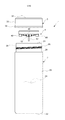
- FIGS. 1 to 4 The mixing container 1 according to the present embodiment is shown in FIGS. 1 to 4 (FIG. 1 is an overall view (front view) of the mixing container 1, FIG. 2 is a plan view of the mixing container 1, and FIG. As shown in FIG. 4, the internal space 2 ⁇ / b> S is released through the opening 21 at the upper edge as shown in FIG. 4 corresponding to FIG. 1.
- the bottomed cylindrical container body 2, the outer lid 3 capable of sealing the opening 21 of the container body 2, and the inner lid 4 disposed in the interior 2 ⁇ / b> S of the container body 2 are provided.
- the container body 2 includes a bottom portion 22, a cylindrical body portion 23 extending upward from the outer peripheral edge of the bottom portion 22, and a radially inner side from the upper end of the body portion 23.
- the shoulder portion 24 (step portion) extending horizontally and the spout portion 25 extending upward from the inner peripheral edge of the shoulder portion 24 are integrally made of synthetic resin.
- the bottom portion 22, the main body portion 23, the shoulder portion 24, and the spout portion 25 are formed concentrically, and the wall thickness is set to substantially the same value.
- the height dimension of the spout portion 25 is set to about one sixth of the height dimension of the main body portion 23, but this ratio is designed according to the internal capacity of the main body portion 23 and the like.
- the inner diameter of the spout portion 25 smaller than the inner diameter of the main body portion 23 can also be set to an appropriate value.
- the inner diameter of the main body portion 23 is set to about 1.1 times the inner diameter of the spout portion 25.
- the container main body 2 of this embodiment is set so that a 330 ml drink can be accommodated in the space partitioned by the bottom 22 and the main body 23.
- the entire region 22 ⁇ / b> A excluding the outer peripheral edge of the bottom portion 22 is set to a partial spherical shape that gradually rises upward toward the center of the bottom portion 22.
- the first screw portion 26 is formed on the outer peripheral surface of the spout portion 25.
- the container main body 2 of this embodiment is the 1st thread part in the height direction center part of the spout part 25. 26 is formed.
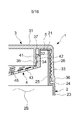
- FIG. 5 an enlarged view of the main part of the cross-sectional view taken along the line AA in FIG. 2
- the mixing container 1 according to the present embodiment is connected to the first screw portion 26 of the container body 2 on the outer side.
- the outer lid 3 can be attached to the container body 2 by screwing the second screw portion 32 of the lid 3.
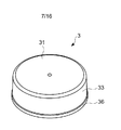
- FIG. 6 is a bottom view of the outer lid 3
- FIG. 7 is a perspective view of the outer lid 3
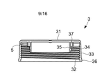
- FIG. FIG. 9 is a perspective view of the outer lid 3 in a state in which the outer lid 3 is moved
- FIG. 9 is a diagram in which only the outer lid 3 is extracted from the cross-sectional view taken along the line AA of FIG. 31, a cylindrical outer peripheral wall portion 33 extending downward from the outer peripheral edge of the outer lid main body portion 31 and provided with a second screw portion 32 on the inner peripheral surface, and the outer lid main body portion 31 being more than the outer peripheral edge.
- the outer diameter of the outer peripheral wall 33 is substantially the same as the outer diameter of the main body 23 of the container main body 2 (see FIG. 1).
- a protruding portion 36 whose outer diameter is set slightly larger than the other portions is provided at the lower end portion and the vicinity of the lower end, and the outer diameter of the protruding portion 36 is set to the container body 2. It is made to correspond to the outer diameter of the main-body part 23 of this.
- the height dimension of the protruding portion 36 is set to about 1/10 of the overall height dimension of the outer peripheral wall portion 33.
- FIG. 1 illustrates a configuration in which a slight gap is formed between the lower end (the protruding portion 36) of the outer lid 3 and the shoulder portion 24 of the container main body 22 in a state where the outer lid 3 is mounted on the container main body 22.
- the height dimension of the outer lid 3 may be appropriately changed so that such a gap is not formed.
- the inner peripheral wall portion 35 has a smaller dimension extending downward from the outer lid main body portion 31 as compared with the outer peripheral wall portion 33 (see FIGS. 8 and 9).
- the mixing container 1 of this embodiment attaches the inner lid 4 to the outer lid 3 by screwing the fourth screw portion 41 of the inner lid 4 to the third screw portion 34 provided on the outer circumferential surface of the inner circumferential wall portion 35. (See FIG. 5).
- the outer lid 3 of the present embodiment is an intermediate wall that extends radially inward from the outer peripheral edge of the outer lid main body portion 31 and extends downward from a predetermined location radially outside the location where the inner peripheral wall portion 35 is formed.
- a portion 37 is provided (see FIG. 5).
- the intermediate wall portion 37 has a smaller dimension extending downward from the outer lid main body portion 31 than the inner peripheral wall portion 35.
- the elastic member 5 (packing) is disposed without a gap between the intermediate wall portion 37 and the outer peripheral wall portion 33. As shown in FIG.
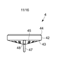
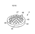
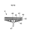
- FIG. 10 to FIG. 16 (FIG. 10 is a front view of the inner lid 4, FIG. 11 is a side view of the inner lid 4, and FIG. 12 is a plan view of the inner lid 4. 13 is a bottom view of the inner lid 4, FIG. 14 is a perspective view of the inner lid 4, FIG. 15 is a perspective view of the inner lid 4 with the top and bottom inverted, and FIG. -B line cross-sectional view), a cylindrical peripheral wall portion 42 provided on the inner peripheral surface with a fourth screw portion 41 corresponding to the "inner lid screwing portion" of the present invention, and the peripheral wall portion 42 It is made of a synthetic resin integrally having an inverted conical inner lid main body 43 extending downward from the lower end.
- a concave step portion 44 is formed at the upper end portion of the peripheral wall portion 42.
- a large number of through holes 45 are formed in the inner lid main body 43.
- through holes 45 having a predetermined opening diameter are formed at equal pitches on a plurality of concentric virtual circles. Specifically, a through hole is formed on each of the first virtual circle having a radius of 4 mm, the second virtual circle having a radius of 8 mm, the third virtual circle having a radius of 12 mm, the fourth virtual circle having a radius of 16 mm, and the virtual circles having the same center. 45 is formed at a predetermined pitch. In this embodiment, 90 ° intervals on the first virtual circle, 45 ° intervals on the second virtual circle, 30 ° intervals on the third virtual circle, and 22.5 ° intervals on the fourth virtual circle. Thus, the through holes 45 are formed.
- the through hole 45 of the present embodiment has an opening diameter set to 3 mm. Further, at the center of the inner lid main body 43, a bar-like upper projection 46 projecting upward and a bar-like lower projection 47 projecting downward are provided. The upper end of the upper protrusion 46 is set to a height position substantially the same as the lower end of the peripheral wall part 42 or a height position slightly higher than the lower end of the peripheral wall part 42.
- the inner lid 4 of the present embodiment includes a finger hooking portion 48 that protrudes downward from the downward surface of the inner lid main body portion 43 and that allows the user to hook a finger.
- a flat finger-hanging portion 48 extending from the vicinity of the outer peripheral edge toward the radial center of the inner lid main body portion 43 is applied.
- toe can also be applied as the finger hanging part 48.
- the inner lid 4 of the present embodiment is provided with a plurality of finger-hanging portions 48 at positions spaced apart by a predetermined pitch in the circumferential direction on the downward surface of the inner lid main body portion 43.
- the finger rests 48 are arranged at 180 ° intervals on the above-described fourth virtual circle having a radius of 16 mm.
- the above-mentioned through-hole 45 is not formed in the location which provided the finger hook part 48 on the 4th virtual circle with a radius of 16 mm.
- the downward surface of the finger rest 48 is set to a flat horizontal surface.
- the lower end of the finger hanging portion 48 is positioned below the finger hanging portion 48 so that the lower end of the finger hanging portion 48 is higher than the center of the inner lid main body portion 43 that is the lowest position on the downward surface of the inner lid main body portion 43.
- Projection dimensions are set.
- it is also possible to set the downward projecting dimension of the finger hanging portion 48 so that the lower end of the finger hanging portion 48 is positioned lower than the center of the inner lid main body portion 43.
- the third screw portion 34 provided on the inner peripheral wall portion 35 of the outer lid 3 and the fourth screw portion 41 provided on the peripheral wall portion 42 of the inner lid 4 are screwed together.
- the inner lid 4 can be handled as a unit body attached to the outer lid 3.
- a second screw portion 32 provided on the outer peripheral wall portion 33 of the outer lid 3 and a first screw portion 26 provided on the spout portion 25 of the container body 2 are provided. It can be stored in a state where the outer lid 3 is attached to the container body 2 by being screwed together.
- the screwing state of the 2nd screw part 32 of the outer cover 3 and the 1st screw part 26 of the container main body 2 is cancelled
- the user can remove the outer lid 3 from the container body 2 by performing a process in which the user rotates either one or both of the outer lid 3 and the container body 2 in a predetermined direction.
- powdered green tea powder may be put directly into the container body 2, but in order to prevent the powder from becoming “dummy”, the powdered green tea powder is poured into an appropriate tea strainer and hot water is poured. You may make it put in the container main body 2 what was extracted by.
- a tea strainer (not shown) that can be set in a stable state on the container body 2 can also be applied.
- the outer lid 3 that is unitized with the inner lid 4 is attached to the container body 2. This is because the user turns one or both of the outer lid 3 and the container body 2 in a predetermined direction in which the second screw portion 32 of the outer lid 3 and the first screw portion 26 of the container body 2 are screwed together. Perform by processing.
- the second screw portion 32 of the outer lid 3 is screwed into the first screw portion 26 of the container body 2 and the outer lid 3 is attached to the container body 2, the upper end of the container body 2 (the upper end of the spout portion 25). ) Hits the downward surface of the elastic member 5 to ensure the airtightness of the internal space 2S of the container body 2 (see FIG. 5).
- the beverage mixing container 1 can evenly mix very small powdered green tea powder into hot water and generate appropriate bubbles by repeatedly passing through the small-diameter through holes 45. Can do.
- the inner lid main body 43 of the inner lid 4 functions as a tea bowl without using a dedicated tea bowl, and a simple manual operation by the user, Matcha powder can be evenly mixed in hot water to make it foam, and even users who lack knowledge and knowledge about tea can quickly and easily make delicious matcha tea.
- the matcha tea that has been lit using the mixing container 1 releases the screwed state of the second screw part 32 of the outer lid 3 and the first screw part 26 of the container body 2, and the spout part 25 of the container body 2. Can be transferred to another teacup and drink, or the mouth can be directly directed to the spout portion 25 of the container body 2 from which the outer lid 3 has been removed.
- the inner lid 4 since the inner lid 4 is attached to the outer lid 3, the inner lid 4 can be removed from the inner space 2 ⁇ / b> S of the container body 2 by removing the outer lid 3 from the container body 2. Therefore, according to the mixing container 1 which concerns on this embodiment, compared with the aspect from which it is requested
- the mixing container 1 can wash the container body 2, the outer lid 3, and the inner lid 4 after use.
- the outer lid 3 and the inner lid 4 that are integrally assembled with each other and are in a unitized state, the user puts a finger on the finger hooking portion 48 of the inner lid 4 and the third screw portion 34 of the outer lid 3.
- the inner lid 4 can be removed from the outer lid 3 in accordance with an operation of rotating the fourth screw portion 41 of the inner lid 4 in a predetermined direction to release the screwed state.
- one finger hanging portion 48 is hung with the thumb and the other finger hanging portion 48
- the screwed state of the inner lid 4 and the outer lid 3 can be smoothly released. Further, when the screwed state of the inner lid 4 and the outer lid 3 is completely released or after the screwed state is almost released, the user picks the downward projecting portion 47 of the inner lid main body 43 with a finger.
- the finger hook portion 48 provided on the inner lid 4 can mix and agitate the powdered green tea powder and hot water by hitting the powdered green tea powder and hot water. That is, the finger hook portion 48 functions as a stirring portion and contributes to the improvement of the stirring performance of the entire mixing container 1.
- the mixing container 1 includes the container main body 2, the outer lid 3, and the inner lid 4, and as the inner lid 4, the through holes 45 penetrating in the height direction are dispersed.
- the object to be mixed since the one having the inner lid main body portion 43 formed in a large number and the finger hook portion 48 projecting downward from the inner lid main body portion 43 is applied, the object to be mixed (this embodiment)
- the container body 2 with the outer lid 3 is shaken in a state in which powdered green tea powder and hot water are accommodated in the form, the mixing object hits the inner lid body portion 43 or passes through the through-hole 45 to efficiently mix. -Can be stirred.
- the finger hooking part 48 of the inner lid 4 also exhibits a function of stirring the object to be mixed, it contributes to improvement of stirring performance.
- the inner lid 4 having a plurality of finger hanging portions 48 is applied, by placing a separate finger on each finger hanging portion 48, the outer lid 3 and the inner lid 4 can be separated.
- the process of releasing the screwed state and the process of screwing the outer lid 3 and the inner lid 4 can be performed more smoothly and appropriately, and greatly contribute to the improvement of the stirring performance.
- the mixing container 1 includes, as the outer lid 3, a disc-shaped outer lid main body portion 31, a cylindrical outer peripheral wall portion 33 extending downward from the outer peripheral edge of the outer lid main body portion 31, and An inner peripheral wall portion 35 extending downward from a predetermined location radially inward of the outer peripheral edge portion of the outer lid main body portion 31, and an inner peripheral wall portion 35 that is radially inward of the outer peripheral edge portion of the outer lid main body portion 31. And an intermediate wall portion 37 that extends downward from a predetermined location radially outside the formation location of the inner peripheral wall portion 35 and can be screwed onto the fourth screw portion 41 of the inner lid 4.
- the third screw portion 34 is provided and the lower end of the intermediate wall portion 37 is in contact with the inner lid 4 when the screw portions 41 and 34 are screwed to each other by a predetermined size.
- the intermediate wall portion 37 of the outer lid 3 abuts against the inner lid 4 and is screwed further. It functions as a stopper that controls the deepening of the state, and is caused by "overtightening" during the screwing process, that is, the process of removing the inner cover 4 from the outer cover 3 (the screwed state between the screw portions 41 and 34). It is possible to prevent / suppress the occurrence of a problem that makes it difficult to perform the (releasing process).
- the screw portions 41 and 34 are screwed together so that the lower end of the intermediate wall portion 37 is in contact with the inner lid 4.
- An appropriate screwed state of the lid 4 can be secured, and the inner lid 4 is unexpectedly moved from the outer lid 3 when the mixing container 1 is shaken strongly with the outer lid 3 mounted on the container body 2. Can be prevented from coming off.
- the mixing container 1 arranges the elastic member 5 in a close contact state in a space partitioned by the outer peripheral wall part 33 and the intermediate wall part 37 in the downward surface of the outer lid main body part 31. Since the upper end of the container body 2 is set so as to contact the elastic member 5 in a state in which the opening 21 of the container is sealed with the outer lid 3, for example, the elastic member is disposed on the entire downward surface of the outer lid body 31.
- the arrangement space of the elastic member 5 can be reduced as compared with the aspect in which the elastic member is disposed in the entire space between the outer peripheral wall portion 31 and the inner peripheral wall portion 35 on the downward surface of the outer lid main body portion 31. It is possible to ensure good airtightness in the mixing container 1 in a state where the opening 21 of the container body 2 is covered with the outer lid 3 while being configured using the minimum elastic member 5, Cost reduction It is possible to achieve.
- the opening diameter of the through hole 45 is set to 3 mm or less, compared with the aspect in which the opening diameter of the through hole 45 is set to a value larger than 3 mm, As a result of testing with various sizes, it was found that foaming can be performed well when applying matcha.
- powdered green tea powder and hot water are exemplified as the object to be mixed, but powders other than green tea (tea powder other than green tea, coffee powder, sports drink powder, supplement powder, sugar, etc. ) And liquids other than hot water (water, tea, milk, carbonated beverages, alcoholic beverages, etc.) can be mixed in the mixing container according to the present invention.
- meringue can be made by mixing egg white and sugar and lathering.
- the mixing container according to the present invention can be used as a container that uniformly mixes different liquids or liquids, powders, solids, and the like as objects to be mixed.
- the shape, number and arrangement (layout) of through holes formed in the inner lid are not particularly limited, and holes other than round holes or holes with irregular shapes may be applied. .
- the opening diameter may be larger than 3 mm.
- the number of finger hooks may be 1 or 3 or more. There are no particular restrictions on the location where the finger-hanging portion is formed on the inner lid.
- each dimension such as the height dimension of the container main body can be appropriately changed according to the inner volume.
- a pour spout that can be opened and closed is formed on the outer lid, and the pour spout is closed when mixing objects to be mixed. After mixing, the pour spout is closed with the outer lid attached to the container body. It is also possible to pour out the completed mixture (beverage, food) in the mixing container from the spout that has been switched from the open state to the open state.
Landscapes
- Engineering & Computer Science (AREA)
- Mechanical Engineering (AREA)
- Food Science & Technology (AREA)
- Closures For Containers (AREA)
- Details Of Rigid Or Semi-Rigid Containers (AREA)
Abstract
La présente invention concerne une cuve de mélange (1) comprenant : un corps principal de cuve à fond (2) dans lequel un espace interne (2S) s'ouvre vers le haut à travers une partie d'ouverture de bord supérieur (21) ; un couvercle externe (3) capable de sceller la partie d'ouverture (21) du corps principal de cuve (2) ; et un couvercle interne (4) disposé à l'intérieur du corps principal de cuve (2) ; le couvercle interne (4) comportant une partie de paroi périphérique cylindrique (42) ayant une partie de vissage de couvercle interne (quatrième partie de filetage (41)) qui peut être vissée sur le couvercle externe (3), une partie de corps principal de couvercle interne (43) dans laquelle de multiples trous traversants (45) pénétrant dans la direction de hauteur sont formés de manière dispersée, et une partie d'accrochage de doigt (48) qui fait saillie vers le bas depuis la partie de corps principal de couvercle interne (43) et contre laquelle un doigt peut s'accrocher. En adoptant cette configuration, il est possible de fournir une cuve de mélange (1) au moyen de laquelle une opération pour retirer le couvercle interne (4) du couvercle externe (3) peut être réalisée en douceur et de manière appropriée.
Priority Applications (2)
| Application Number | Priority Date | Filing Date | Title |
|---|---|---|---|
| JP2018500194A JP6647635B2 (ja) | 2016-02-16 | 2017-02-16 | 混合容器 |
| US16/477,111 US10835082B2 (en) | 2016-02-16 | 2017-02-16 | Mixing vessel |
Applications Claiming Priority (2)
| Application Number | Priority Date | Filing Date | Title |
|---|---|---|---|
| JP2016026682 | 2016-02-16 | ||
| JP2016-026682 | 2016-12-09 |
Publications (1)
| Publication Number | Publication Date |
|---|---|
| WO2017142024A1 true WO2017142024A1 (fr) | 2017-08-24 |
Family
ID=59625191
Family Applications (1)
| Application Number | Title | Priority Date | Filing Date |
|---|---|---|---|
| PCT/JP2017/005728 Ceased WO2017142024A1 (fr) | 2016-02-16 | 2017-02-16 | Cuve de mélange |
Country Status (3)
| Country | Link |
|---|---|
| US (1) | US10835082B2 (fr) |
| JP (1) | JP6647635B2 (fr) |
| WO (1) | WO2017142024A1 (fr) |
Cited By (1)
| Publication number | Priority date | Publication date | Assignee | Title |
|---|---|---|---|---|
| JP2016209225A (ja) * | 2015-05-07 | 2016-12-15 | 戎屋化学工業株式会社 | シェイカー |
Families Citing this family (2)
| Publication number | Priority date | Publication date | Assignee | Title |
|---|---|---|---|---|
| KR20210001238U (ko) * | 2019-11-27 | 2021-06-04 | 장기수 | 식품 포장용기 |
| USD912459S1 (en) * | 2019-12-16 | 2021-03-09 | Helen Of Troy Limited | Manual coffee grinder |
Citations (4)
| Publication number | Priority date | Publication date | Assignee | Title |
|---|---|---|---|---|
| JPH05198337A (ja) * | 1992-01-17 | 1993-08-06 | Mitsubishi Heavy Ind Ltd | コネクタ |
| JP2006347551A (ja) * | 2005-06-13 | 2006-12-28 | Mikasa Sangyo Kk | スポイト付きキャップ |
| JP3181593U (ja) * | 2012-12-03 | 2013-02-14 | スケーター株式会社 | 卵黄撹拌調理器 |
| JP2013203448A (ja) * | 2012-03-29 | 2013-10-07 | Nippon Closures Co Ltd | 容器蓋 |
Family Cites Families (7)
| Publication number | Priority date | Publication date | Assignee | Title |
|---|---|---|---|---|
| DE4121540A1 (de) * | 1991-06-28 | 1993-01-07 | Finke Robert Gmbh | Flaschenverschlusskappe fuer zwei-komponenten-packungen |
| DE19806020A1 (de) * | 1998-02-13 | 1999-08-26 | Maxs Ag | Schüttelbecher |
| DE10202147A1 (de) * | 2002-01-17 | 2003-09-18 | Birkmayer Gesundheitsprodukte | Kunststoff-Flaschenverschluss |
| KR200363704Y1 (ko) * | 2004-07-01 | 2004-10-06 | 임효빈 | 오픈시 내용물 혼합이 가능하도록 하는 덮개 |
| US7588142B1 (en) * | 2005-11-18 | 2009-09-15 | Rexam Closures And Containers Inc. | Additive delivery system closure |
| EP2292525A1 (fr) * | 2009-09-04 | 2011-03-09 | Obrist Closures Switzerland GmbH | Ensemble de fermeture de conteneur |
| US8967412B2 (en) * | 2010-08-03 | 2015-03-03 | James A Loging | Drinking cup with lid and flow control element |
-
2017
- 2017-02-16 US US16/477,111 patent/US10835082B2/en active Active
- 2017-02-16 WO PCT/JP2017/005728 patent/WO2017142024A1/fr not_active Ceased
- 2017-02-16 JP JP2018500194A patent/JP6647635B2/ja active Active
Patent Citations (4)
| Publication number | Priority date | Publication date | Assignee | Title |
|---|---|---|---|---|
| JPH05198337A (ja) * | 1992-01-17 | 1993-08-06 | Mitsubishi Heavy Ind Ltd | コネクタ |
| JP2006347551A (ja) * | 2005-06-13 | 2006-12-28 | Mikasa Sangyo Kk | スポイト付きキャップ |
| JP2013203448A (ja) * | 2012-03-29 | 2013-10-07 | Nippon Closures Co Ltd | 容器蓋 |
| JP3181593U (ja) * | 2012-12-03 | 2013-02-14 | スケーター株式会社 | 卵黄撹拌調理器 |
Cited By (1)
| Publication number | Priority date | Publication date | Assignee | Title |
|---|---|---|---|---|
| JP2016209225A (ja) * | 2015-05-07 | 2016-12-15 | 戎屋化学工業株式会社 | シェイカー |
Also Published As
| Publication number | Publication date |
|---|---|
| US10835082B2 (en) | 2020-11-17 |
| US20200253426A1 (en) | 2020-08-13 |
| JP6647635B2 (ja) | 2020-02-14 |
| JPWO2017142024A1 (ja) | 2019-04-11 |
Similar Documents
| Publication | Publication Date | Title |
|---|---|---|
| US8136978B2 (en) | Tumbler with stirring assembly | |
| CA2713641C (fr) | Broc avec infuseur | |
| US3820692A (en) | Food shaker and blender | |
| US9538884B2 (en) | Agitator for food and beverage mixer | |
| US20170361984A1 (en) | Shaker bottle with plastic liner | |
| US10104994B2 (en) | Apparatus, device, and methods for mixing substances | |
| US10532866B2 (en) | Container cap assembly | |
| US10368697B2 (en) | Egg cracker, egg separator and/or egg mixer | |
| US20060153003A1 (en) | Drinking extension for blender container | |
| US20150329255A1 (en) | Jar Lid Including an Accessory | |
| JP2015500186A (ja) | 攪拌器を備えたシェイク容器。 | |
| JP2008545467A (ja) | 混合用組立体 | |
| US20160249773A1 (en) | Liquid agitation container | |
| JP6647635B2 (ja) | 混合容器 | |
| US20050105387A1 (en) | Drink bottle with integrated mixing blades | |
| EP4213692A1 (fr) | Bouteille à secouer pour préparation d'aliments nutritifs sains | |
| US20130201784A1 (en) | Batter shaker | |
| KR101740663B1 (ko) | 환제 내장용 음료 용기 마개 | |
| US20230234769A1 (en) | Bottle having internal mixing compartment | |
| KR20180026436A (ko) | 쉐이크 기능을 갖는 용기 | |
| US1488775A (en) | Beverage mixer | |
| JP7444554B2 (ja) | 難溶性飲料製品 | |
| KR20100000428A (ko) | 혼합과 머그컵 | |
| US20150196881A1 (en) | Top stirring implement for natural peanut butter | |
| US12017819B2 (en) | Mixing bottle and method therefor |
Legal Events
| Date | Code | Title | Description |
|---|---|---|---|
| 121 | Ep: the epo has been informed by wipo that ep was designated in this application |
Ref document number: 17753279 Country of ref document: EP Kind code of ref document: A1 |
|
| WWE | Wipo information: entry into national phase |
Ref document number: 2018500194 Country of ref document: JP |
|
| NENP | Non-entry into the national phase |
Ref country code: DE |
|
| 122 | Ep: pct application non-entry in european phase |
Ref document number: 17753279 Country of ref document: EP Kind code of ref document: A1 |