WO2017142060A1 - Dispositif de transmission d'énergie - Google Patents
Dispositif de transmission d'énergie Download PDFInfo
- Publication number
- WO2017142060A1 WO2017142060A1 PCT/JP2017/005862 JP2017005862W WO2017142060A1 WO 2017142060 A1 WO2017142060 A1 WO 2017142060A1 JP 2017005862 W JP2017005862 W JP 2017005862W WO 2017142060 A1 WO2017142060 A1 WO 2017142060A1
- Authority
- WO
- WIPO (PCT)
- Prior art keywords
- gear
- external
- external gear
- peripheral surface
- transmission device
- Prior art date
- Legal status (The legal status is an assumption and is not a legal conclusion. Google has not performed a legal analysis and makes no representation as to the accuracy of the status listed.)
- Ceased
Links
Images


Classifications
-
- F—MECHANICAL ENGINEERING; LIGHTING; HEATING; WEAPONS; BLASTING
- F16—ENGINEERING ELEMENTS AND UNITS; GENERAL MEASURES FOR PRODUCING AND MAINTAINING EFFECTIVE FUNCTIONING OF MACHINES OR INSTALLATIONS; THERMAL INSULATION IN GENERAL
- F16H—GEARING
- F16H3/00—Toothed gearings for conveying rotary motion with variable gear ratio or for reversing rotary motion
- F16H3/44—Toothed gearings for conveying rotary motion with variable gear ratio or for reversing rotary motion using gears having orbital motion
- F16H3/62—Gearings having three or more central gears
- F16H3/66—Gearings having three or more central gears composed of a number of gear trains without drive passing from one train to another
- F16H3/663—Gearings having three or more central gears composed of a number of gear trains without drive passing from one train to another with conveying rotary motion between axially spaced orbital gears, e.g. a stepped orbital gear or Ravigneaux
-
- F—MECHANICAL ENGINEERING; LIGHTING; HEATING; WEAPONS; BLASTING
- F16—ENGINEERING ELEMENTS AND UNITS; GENERAL MEASURES FOR PRODUCING AND MAINTAINING EFFECTIVE FUNCTIONING OF MACHINES OR INSTALLATIONS; THERMAL INSULATION IN GENERAL
- F16H—GEARING
- F16H3/00—Toothed gearings for conveying rotary motion with variable gear ratio or for reversing rotary motion
- F16H3/44—Toothed gearings for conveying rotary motion with variable gear ratio or for reversing rotary motion using gears having orbital motion
- F16H3/62—Gearings having three or more central gears
- F16H3/66—Gearings having three or more central gears composed of a number of gear trains without drive passing from one train to another
- F16H3/666—Gearings having three or more central gears composed of a number of gear trains without drive passing from one train to another with intermeshing orbital gears
-
- F—MECHANICAL ENGINEERING; LIGHTING; HEATING; WEAPONS; BLASTING
- F16—ENGINEERING ELEMENTS AND UNITS; GENERAL MEASURES FOR PRODUCING AND MAINTAINING EFFECTIVE FUNCTIONING OF MACHINES OR INSTALLATIONS; THERMAL INSULATION IN GENERAL
- F16H—GEARING
- F16H57/00—General details of gearing
- F16H57/02—Gearboxes; Mounting gearing therein
- F16H57/021—Shaft support structures, e.g. partition walls, bearing eyes, casing walls or covers with bearings
-
- F—MECHANICAL ENGINEERING; LIGHTING; HEATING; WEAPONS; BLASTING
- F16—ENGINEERING ELEMENTS AND UNITS; GENERAL MEASURES FOR PRODUCING AND MAINTAINING EFFECTIVE FUNCTIONING OF MACHINES OR INSTALLATIONS; THERMAL INSULATION IN GENERAL
- F16H—GEARING
- F16H57/00—General details of gearing
- F16H57/02—Gearboxes; Mounting gearing therein
- F16H57/023—Mounting or installation of gears or shafts in the gearboxes, e.g. methods or means for assembly
-
- F—MECHANICAL ENGINEERING; LIGHTING; HEATING; WEAPONS; BLASTING
- F16—ENGINEERING ELEMENTS AND UNITS; GENERAL MEASURES FOR PRODUCING AND MAINTAINING EFFECTIVE FUNCTIONING OF MACHINES OR INSTALLATIONS; THERMAL INSULATION IN GENERAL
- F16H—GEARING
- F16H57/00—General details of gearing
- F16H57/02—Gearboxes; Mounting gearing therein
- F16H57/021—Shaft support structures, e.g. partition walls, bearing eyes, casing walls or covers with bearings
- F16H2057/0216—Intermediate shaft supports, e.g. by using a partition wall
-
- F—MECHANICAL ENGINEERING; LIGHTING; HEATING; WEAPONS; BLASTING
- F16—ENGINEERING ELEMENTS AND UNITS; GENERAL MEASURES FOR PRODUCING AND MAINTAINING EFFECTIVE FUNCTIONING OF MACHINES OR INSTALLATIONS; THERMAL INSULATION IN GENERAL
- F16H—GEARING
- F16H2200/00—Transmissions for multiple ratios
- F16H2200/003—Transmissions for multiple ratios characterised by the number of forward speeds
- F16H2200/0073—Transmissions for multiple ratios characterised by the number of forward speeds the gear ratios comprising eleven forward speeds
-
- F—MECHANICAL ENGINEERING; LIGHTING; HEATING; WEAPONS; BLASTING
- F16—ENGINEERING ELEMENTS AND UNITS; GENERAL MEASURES FOR PRODUCING AND MAINTAINING EFFECTIVE FUNCTIONING OF MACHINES OR INSTALLATIONS; THERMAL INSULATION IN GENERAL
- F16H—GEARING
- F16H2200/00—Transmissions for multiple ratios
- F16H2200/20—Transmissions using gears with orbital motion
- F16H2200/2002—Transmissions using gears with orbital motion characterised by the number of sets of orbital gears
- F16H2200/2007—Transmissions using gears with orbital motion characterised by the number of sets of orbital gears with two sets of orbital gears
-
- F—MECHANICAL ENGINEERING; LIGHTING; HEATING; WEAPONS; BLASTING
- F16—ENGINEERING ELEMENTS AND UNITS; GENERAL MEASURES FOR PRODUCING AND MAINTAINING EFFECTIVE FUNCTIONING OF MACHINES OR INSTALLATIONS; THERMAL INSULATION IN GENERAL
- F16H—GEARING
- F16H2200/00—Transmissions for multiple ratios
- F16H2200/20—Transmissions using gears with orbital motion
- F16H2200/202—Transmissions using gears with orbital motion characterised by the type of Ravigneaux set
- F16H2200/2023—Transmissions using gears with orbital motion characterised by the type of Ravigneaux set using a Ravigneaux set with 4 connections
-
- F—MECHANICAL ENGINEERING; LIGHTING; HEATING; WEAPONS; BLASTING
- F16—ENGINEERING ELEMENTS AND UNITS; GENERAL MEASURES FOR PRODUCING AND MAINTAINING EFFECTIVE FUNCTIONING OF MACHINES OR INSTALLATIONS; THERMAL INSULATION IN GENERAL
- F16H—GEARING
- F16H2200/00—Transmissions for multiple ratios
- F16H2200/20—Transmissions using gears with orbital motion
- F16H2200/203—Transmissions using gears with orbital motion characterised by the engaging friction means not of the freewheel type, e.g. friction clutches or brakes
- F16H2200/2046—Transmissions using gears with orbital motion characterised by the engaging friction means not of the freewheel type, e.g. friction clutches or brakes with six engaging means
-
- F—MECHANICAL ENGINEERING; LIGHTING; HEATING; WEAPONS; BLASTING
- F16—ENGINEERING ELEMENTS AND UNITS; GENERAL MEASURES FOR PRODUCING AND MAINTAINING EFFECTIVE FUNCTIONING OF MACHINES OR INSTALLATIONS; THERMAL INSULATION IN GENERAL
- F16H—GEARING
- F16H2200/00—Transmissions for multiple ratios
- F16H2200/20—Transmissions using gears with orbital motion
- F16H2200/203—Transmissions using gears with orbital motion characterised by the engaging friction means not of the freewheel type, e.g. friction clutches or brakes
- F16H2200/2048—Transmissions using gears with orbital motion characterised by the engaging friction means not of the freewheel type, e.g. friction clutches or brakes with seven engaging means
-
- F—MECHANICAL ENGINEERING; LIGHTING; HEATING; WEAPONS; BLASTING
- F16—ENGINEERING ELEMENTS AND UNITS; GENERAL MEASURES FOR PRODUCING AND MAINTAINING EFFECTIVE FUNCTIONING OF MACHINES OR INSTALLATIONS; THERMAL INSULATION IN GENERAL
- F16H—GEARING
- F16H2200/00—Transmissions for multiple ratios
- F16H2200/20—Transmissions using gears with orbital motion
- F16H2200/2097—Transmissions using gears with orbital motion comprising an orbital gear set member permanently connected to the housing, e.g. a sun wheel permanently connected to the housing
Definitions
- the invention of the present disclosure disclosed in the present specification relates to a power transmission device.
- the main object of the present disclosure is to shorten the shaft length of the power transmission device.
- the invention of the present disclosure has taken the following measures in order to achieve the main object described above.
- the power transmission device of the present disclosure is: A gear group including a first external gear and a second external gear having a diameter larger than that of the first external gear is arranged coaxially in the case, and the power input to the input member is transmitted to the gear group.
- a power transmission device for transmitting to the output member via The first external gear includes a side wall portion extending radially inward from an inner peripheral surface of the case, and a hollow cylindrical portion extending in an axial direction from the radial inner side of the side wall portion.
- a support having a side wall portion extending radially inward from the inner peripheral surface of the case and a hollow cylindrical portion extending in the axial direction from the radial inner side of the side wall portion.
- the member is provided between the first external gear and the second external gear having a diameter larger than that of the first external gear.
- a first bearing is provided on the outer peripheral surface of the cylindrical portion to rotatably support one of the first external gear and the second external gear
- a second bearing is provided on the inner peripheral surface of the cylindrical portion. The other one of the first external gear and the second external gear is rotatably supported.
- the axial length of a power transmission device can be shortened.
- the first bearing and the second bearing are disposed with the cylindrical portion of the support member interposed therebetween, and one of the inner ring or the outer ring of the bearing is fixed to the cylindrical portion, so that there is a gap between the inner ring and the outer ring of the bearing.
- an excessive difference in rotational speed does not occur, and a load on one bearing is not transmitted to the other bearing.
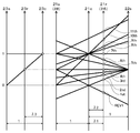
- FIG. 3 is an operation table showing the relationship between each gear position of the automatic transmission 20 and the operation states of clutches and brakes. 3 is a velocity diagram showing a ratio of a rotational speed of each rotary element to an input rotational speed of the automatic transmission 20.
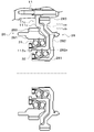
- FIG. It is sectional drawing of the principal part containing the center support in a power transmission device.
- FIG. 1 is a schematic configuration diagram of a power transmission device 10 according to an embodiment of the present disclosure.
- the power transmission device 10 is connected to a crankshaft of an engine EG (internal combustion engine) (not shown) and / or a rotor of an electric motor as a drive source mounted horizontally on the front portion of the front-wheel drive vehicle.
- power (torque) from the engine EG or the like can be transmitted to left and right front wheels (drive wheels) (not shown).
- the power transmission device 10 includes a transmission case (stationary member) in addition to an automatic transmission 20 that shifts power transmitted from an engine EG or the like to an input shaft (input member) 20i and transmits the power to the front wheels of the vehicle. ) 11, fluid transmission device (starting device) 12, and the like.
- the fluid transmission device 12 is configured as a fluid torque converter with a lock-up clutch including a pump impeller, a turbine runner, a stator, a one-way clutch, a lock-up clutch, and the like.
- the fluid transmission device 12 may be a simple fluid coupling.
- the automatic transmission 20 is configured as an 11-speed transmission, and, as shown in FIG. 1, in addition to the input shaft 20i, a counter shaft extending in parallel with the input shaft (first shaft) 20i.
- a compound planetary gear mechanism configured by combining an output gear (output member) 20o disposed on the (second shaft) 20c and a single pinion type first planetary gear 21 and a double pinion type second planetary gear 22 As a Ravigneaux type planetary gear mechanism 25 and a double pinion type third planetary gear 23.
- the output gear 20o is an external gear, and is connected to the left and right front wheels via a differential gear including a differential ring gear meshing with the output gear 20o and a drive shaft (both not shown).
- the first and second planetary gears 21 and 22 and the third planetary gear 23 constituting the Ravigneaux type planetary gear mechanism 25 are from the starting device 12, that is, the engine EG side (the right side in FIG. 1).
- the third planetary gear 23, the first planetary gear 21, and the second planetary gear 22 are arranged in the transmission case 11 so as to be arranged in this order.
- the Ravigneaux planetary gear mechanism 25 includes a first sun gear 21s and a second sun gear 22s that are external gears, a first ring gear 21r that is an internal gear disposed concentrically with the first sun gear 21s, and a first sun gear 21s. And a plurality of first pinion gears (long pinion gears) 21p meshing with the first ring gear 21r, a plurality of second pinion gears (short pinion gears) 22p meshing with the second sun gear 22s and the plurality of first pinion gears 21p, and a plurality of first pins.
- the first carrier 21c holds the pinion gear 21p and the plurality of second pinion gears 22p so as to be rotatable (rotatable) and revolved.
- the first sun gear 21s, the first carrier 21c, the first pinion gear 21p, and the first ring gear 21r of the Ravigneaux type planetary gear mechanism 25 constitute a single pinion type first planetary gear 21.
- the second sun gear 22s, the first carrier 21c, the first and second pinion gears 21p and 22p, and the first ring gear 21r of the Ravigneaux type planetary gear mechanism 25 constitute a double pinion type second planetary gear 22.
- the Ravigneaux type planetary gear mechanism 25 has a gear ratio ⁇ 1 of the single pinion type first planetary gear 21 (the number of teeth of the first sun gear 21s / the number of teeth of the first ring gear 21r), for example, ⁇ 1.
- a first drive gear 26, which is an external gear, is always connected coaxially to the first ring gear 21r of the Ravigneaux planetary gear mechanism 25, and the first ring gear 21r and the first drive gear 26 are always integrated. Rotate or stop.
- a first driven gear 27, which is an external gear is always connected to the output gear 20o of the automatic transmission 20 coaxially. The first driven gear 27 meshes with the first drive gear 26, and always rotates or stops integrally with the output gear 20o.
- the first drive gear 26 and the first driven gear 27 to which power is transmitted from the first drive gear 26 constitute a first gear train G1, and the first ring gear 21r is an output element of the Ravigneaux type planetary gear mechanism 25. Function as.
- the second sun gear 21s of the Ravigneaux type planetary gear mechanism 25 is always connected coaxially with the second drive gear 28, which is an external gear, and the first sun gear 21s and the second drive gear 28 are always connected. Rotate or stop together.
- the second drive gear 28 and the second driven gear (external gear) 29 that meshes with the second drive gear 28 constitute a second gear train G2.
- the gear ratio gr2 (number of teeth of the second driven gear 29 / number of teeth of the second drive gear 28) of the second gear train G2 is the gear ratio gr1 of the first gear train G1 (number of teeth of the first driven gear 27 / first gear).
- the number of teeth of the drive gear 26 is different.
- the third planetary gear 23 meshes with a third sun gear (fixed element) 23s that is an external gear and a third ring gear (output element) 23r that is an internal gear arranged concentrically with the third sun gear 23s. And a third carrier 23c (input element) for holding a plurality of sets of two pinion gears 23pa and 23pb, one of which is meshed with the third sun gear 23s and the other of which is meshed with the third ring gear 23r.
- the third sun gear 23s of the third planetary gear 23 is non-rotatably connected (fixed) to the transmission case 11 via a support member (front support) (not shown).
- the third carrier 23c of the third planetary gear 23 is always connected to the input shaft 20i, and always rotates or stops integrally with the input shaft 20i.
- the third planetary gear 23 functions as a so-called reduction gear, decelerates the power transmitted to the third carrier 23c as an input element, and outputs it from the third ring gear 23r as an output element.
- the automatic transmission 20 includes a clutch C1 (third engagement element), a clutch C2 (fourth engagement element), and a clutch C3 (fifth engagement element) for changing the power transmission path from the input shaft 20i to the output gear 20o.
- Engagement element clutch C4 (sixth engagement element), brake B1 (first engagement element), brake B2 (second engagement element), and clutch C5 (output side engagement element).
- the clutch C1 connects and disconnects the third ring gear 23r of the third planetary gear 23 and the second sun gear 22s of the Ravigneaux planetary gear mechanism 25 from each other.
- the clutch C2 connects the input shaft 20i and the first carrier 21c of the Ravigneaux type planetary gear mechanism 25 to each other and releases the connection between them.
- the clutch C3 connects the third ring gear 23r of the third planetary gear 23 and the first sun gear 21s of the Ravigneaux type planetary gear mechanism 25 to each other and releases the connection therebetween.
- the clutch C4 connects the third carrier 23c of the third planetary gear 23, that is, the input shaft 20i and the first sun gear 21s of the Ravigneaux type planetary gear mechanism 25 to each other and releases the connection therebetween.
- the brake B1 fixes (connects) the first sun gear 21s (first fixable element) of the Ravigneaux type planetary gear mechanism 25 to the transmission case 11 in a non-rotatable manner and releases the first sun gear 21s from the transmission case 11 It is.
- the brake B2 fixes (connects) the first carrier 21c of the Ravigneaux type planetary gear mechanism 25 to the transmission case 11 in a non-rotatable manner and releases the fixing to the first carrier 21c.
- the first carrier 21c is fixed to the transmission case 11 so as not to rotate.
- the clutch C5 connects the second driven gear 29 and the output gear 20o (first driven gear 27) of the second gear train G2 to each other and releases the connection between them.
- the clutches C1, C2, C3, C4 and C5 a piston, a plurality of friction engagement plates (friction plates and separator plates), an engagement oil chamber to which hydraulic oil is supplied, a centrifugal hydraulic pressure cancellation chamber, and the like, respectively.
- a multi-plate friction type hydraulic clutch (friction engagement element) having a hydraulic servo constituted by is adopted.
- the brakes B1 and B2 a multi-plate friction hydraulic brake (having a hydraulic servo including a piston, a plurality of friction engagement plates (friction plates and separator plates), an engagement oil chamber to which hydraulic oil is supplied, etc.) A friction engagement element) is employed.
- the clutches C1 to C5 and the brakes B1 and B2 operate by receiving and supplying hydraulic oil from a hydraulic control device (not shown).
- FIG. 2 is an operation table showing the relationship between the respective shift speeds of the automatic transmission 20 and the operation states of the clutches C1 to C5 and the brakes B1 and B2.
- FIG. 3 shows each rotation with respect to the input rotation speed of the automatic transmission 20. It is a speed diagram which shows ratio of the rotational speed of an element.
- FIG. 2 shows the torque transmission directions of the first drive gear 26 and the second drive gear 28 at each shift stage, and “positive” in FIG. 2 indicates the first drive gear 26 or the second drive gear 28.
- the direction of torque transmission indicates the same direction as the direction in which torque is transmitted from the engine EG to the vehicle wheel (front wheel), and “reverse” indicates the direction of torque transmission of the first drive gear 26 or the second drive gear 28.
- the clutches C1 to C5 and the brakes B1 and B2 are engaged or disengaged as shown in FIG. 2, so that there are eleven types in the forward rotation direction and reverse rotation between the input shaft 20i and the output gear 20o.
- One power transmission path in the direction that is, a forward speed and a reverse speed from the first speed to the eleventh speed can be set.
- the motive power input to the input shaft 20i is one of the first gear train G1, the second gear train G2, the first gear train G1, and the second gear train G2, depending on the set gear position.
- the output gear 20o To the output gear 20o.
- the power input to the input shaft 20i is first in the first, second, fourth to seventh, ninth and tenth speed forward stages and reverse stages. It is transmitted to the output gear 20o via the gear train G1, transmitted to the output gear 20o via the second gear train G2 at the 11th forward gear, and first at the 3rd and 8th forward gears. It is transmitted to the output gear 20o via the first gear train G1 and the second gear train G2. That is, the first gear train G1 is a gear train in which torque is transmitted in the forward and reverse gears of the first to tenth speeds, and the second gear train G2 is the forward gears of the third, eighth, and eleventh gears. Is a gear train in which torque is transmitted.
- the transmission case 11 has an annular center support (intermediate support portion) that is located between the first drive gear 26 and the second drive gear 28 and forms a part of the transmission case 11 (stationary member). 11c is fixed.
- FIG. 4 is a cross-sectional view of a main part including a center support in the power transmission device.
- the center support 11c includes an annular side wall portion 111c extending radially inward from the inner peripheral surface of the transmission case 11, and a first drive gear in the axial direction from the inner peripheral portion of the side wall portion 111c.
- a cylindrical portion 112c extending to the 26th side (Ravigneaux type planetary gear mechanism 25 side) and having a central hole formed therein.
- the first drive gear 26 is disposed concentrically on the outer side in the radial direction with respect to the cylindrical portion 112c of the center support 11c, and has a first cylindrical portion 261 formed with a center hole having an inner diameter larger than the outer diameter of the cylindrical portion 112c. And a first external tooth portion 263 formed on the outer peripheral surface of the first cylindrical portion 261.
- a first bearing 31 is interposed between the cylindrical portion 112c (outer peripheral surface) of the center support 11c and the first cylindrical portion 261 (inner peripheral surface) of the first drive gear 26, and the first drive gear 26 ( The first cylindrical portion 261) is rotatably supported by the center support 11c (cylindrical portion 112c) via the first bearing 31.
- the 1st bearing 31 can be comprised as a combination angular contact ball bearing which can receive a radial load and a thrust load of both directions, for example.
- the first external gear portion 263 of the first drive gear 26 meshes with an external gear portion (not shown) of the first driven gear 27.
- the second drive gear 28 is disposed concentrically on the radially inner side with respect to the cylindrical portion 112c of the center support 11c, and has a second cylindrical portion 281 formed with a center hole having an outer diameter smaller than the inner diameter of the cylindrical portion 112c.
- the second cylindrical portion 281 is formed on the outer peripheral surface of the second side wall portion 282 and the annular second side wall portion 282 extending radially outward from the axial direction (third planetary gear 23 side) end portion. 2 external tooth portions 283.
- a second bearing 32 is interposed between the cylindrical portion 112c (inner peripheral surface) of the center support 11c and the second cylindrical portion 281 (outer peripheral surface) of the second drive gear 28, and the second drive gear 28 (
- the second cylindrical portion 281) is rotatably supported by the center support 11c (cylindrical portion 112c) via the second bearing 32.
- the 2nd bearing 32 can be comprised as a combination angular contact ball bearing which can receive a radial load and a thrust load of both directions, for example.
- the second side wall portion 282 of the second drive gear 28 has a substantially uniform thickness and is recessed toward the third planetary gear 23 in the axial direction, and the first drive gear in the axial direction on the radially inner side of the second external tooth portion 283.
- a concave portion 282a having an opening on the 26th side (Ravigneaux type planetary gear mechanism 25 side) is formed.
- the second external tooth portion 283 of the second drive gear 28 meshes with an external tooth portion (not shown) of the second driven gear 29.
- the cylindrical portion 112c of the center support 11c supports the first drive gear 26 in the radial direction on the outer peripheral surface and supports the second drive gear 28 in the radial direction on the inner peripheral surface.
- the gear ratio gr2 of the second gear train G2 constituted by the second drive gear 28 and the second driven gear 29 is the gear ratio gr1 of the first gear train G1 constituted by the first drive gear 26 and the first driven gear 27.
- the first outer tooth portion 263 of the first drive gear 26 has a smaller outer diameter than the second outer tooth portion 283 of the second drive gear 28.
- the side wall 111c of the center support 11c is a shaft that enters from the radially outer side of the first external tooth portion 263 of the first drive gear 26 to the radially inner side (recessed portion 282a) of the second external tooth portion 283 of the second drive gear 28. And a hollow portion 111cb that is recessed in the same direction along the hollow shape of the second side wall portion 282 with a substantially uniform thickness on the radially inner side of the second external tooth portion 283 of the second drive gear 28. And have. Thereby, since the center support 11c can be arrange
- the center support 11c (side wall portion 111c) is enhanced in rigidity by forming the bent portion 111ca, and therefore the first drive gear 26 and the second drive gear 28 supported by the center support 11c (cylindrical portion 112c).
- the deformation in the radial direction can be suppressed, and the generation of noise and vibration can be suppressed.
- a part of the first cylindrical part 261 and a part of the first external tooth part 263 of the first drive gear 26 are in the radial direction of the bent part 111ca provided on the side wall part 111c of the center support 11c.
- the side wall portion 111c of the center support 11c is arranged so as to enter inside, and has a cutout portion in which a part in the circumferential direction is cut out (see the lower portion of the side wall portion 111c in FIG. 4).
- the first drive gear 26 is meshed with the first driven gear 27 at the notch.
- the axial length can be further shortened by allowing at least a part of the first drive gear 26 to enter the radially inner side of the bent portion 111ca.
- the center support 11c is provided with a notch, and the first external gear 263 (first drive gear 26) is engaged with the first driven gear 27 at the notch, so that the shaft length is shortened. However, torque can be transmitted from the first drive gear 26 to the first driven gear 27.
- the first gear train G1 (first drive gear 26) has a higher torque transmission frequency and a larger transmission torque than the second gear train G2 (second drive gear 28).
- the first bearing 31 that supports the first drive gear 26 is required to have a higher load capacity than the second bearing 32 that supports the second drive gear 28.
- the first bearing 31 is disposed so as to support the first drive gear 26 on the outer peripheral surface (outer diameter side) of the cylindrical portion 112c of the center support 11c, and the inner peripheral surface (inner diameter side) of the cylindrical portion 112c. Since the second bearing 32 is disposed so as to support the second drive gear 28, the first bearing 31 (rolling element) can be easily increased in diameter, and a high load capacity can be ensured.
- first bearing 31 is arranged to support the first drive gear 26 on the outer peripheral surface of the cylindrical portion 112c of the center support 11c as a stationary member
- second bearing 32 is arranged on the inner peripheral surface of the cylindrical portion 122c. It arrange
- the second bearing is disposed on the outer peripheral surface of the cylindrical portion of the center support (stationary member), and the inner peripheral surface of the cylindrical portion of the second drive gear is supported by the second bearing, and the cylindrical portion of the second drive gear is supported.
- the first drive gear 26 rotates forward with a relatively large torque transmission
- the second drive gear 28 rotates reversely to the first drive gear 26. Idle in the direction.
- a large rotational speed difference is generated between the inner ring and the outer ring of the first bearing disposed between the first drive gear and the second drive gear.
- the load is transmitted to the second bearing via the second drive gear. .
- the first bearing 31 and the second bearing 31 Since there is no large rotational speed difference between the inner ring and the outer ring in any of the bearings 32, and the cylindrical portion 112c of the center support 11c is disposed between the first bearing 31 and the second bearing 32, A load acting on one of the first bearing 31 and the second bearing 32 is not transmitted to the other bearing. Thereby, the load concerning the 1st bearing 31 and the 2nd bearing 32 can be reduced.
- the first drive gear 26 and the first driven gear 27 (first gear train G1) meshing with each other, the second drive gear 28 and the second driven gear 29 (second gear train G2) meshing with each other, the output gear 20o, and
- the differential ring gear that meshes with the helical gear is constituted by a helical gear.
- the first drive gear 26 and the first driven gear 27 are configured so that the output gear 20o and the diff ring gear are in a state where the first drive gear 26 transmits torque in the forward direction (the same direction as the torque transmitted from the engine EG to the wheels).
- the twist direction of the is determined.
- the second drive gear 28 and the second driven gear 29 act on the counter shaft 20c from the output gear 20o by the meshing of the output gear 20o and the diff ring gear in a state where the second drive gear 28 transmits torque in the positive direction.
- the twisting direction of the gear is determined such that the thrust force acting on the counter shaft 20c from the second driven gear 29 cancels out due to the meshing of the second driving gear 28 and the second driven gear 29.
- the direction of the thrust force acting on each of the first drive gear 26, the first driven gear 27, the second drive gear 28, the second driven gear 29, and the output gear 20o at the eighth forward speed is indicated by a black arrow. Is shown.
- the first driven gear 27 and the second driven gear 29 have the same twisting direction as that of the output gear 20o.
- the first drive gear 26 has a tooth twisting direction opposite to that of the first driven gear 27, and the second drive gear 28 has a tooth twisting direction opposite to that of the second driven gear 29.
- the side wall portion 111c that extends radially inward from the inner peripheral surface of the transmission case 11, and the cylindrical portion that extends in the axial direction from the inner peripheral portion of the side wall portion 111c.
- a center support 11c having 112c is formed between the first drive gear 26 having a small diameter and the second drive gear 28 having a large diameter.
- the first drive gear 26 is rotatably supported by the first bearing 31 on the outer peripheral surface of the cylindrical portion 112c of the center support 11c, and the second drive gear 28 is rotated by the second bearing 32 on the inner peripheral surface of the cylindrical portion 112c. Support freely.
- the 1st bearing 31 and the 2nd bearing 32 can be arrange
- the length can be shortened.
- the second external tooth portion of the second drive gear 28 is formed as the side wall portion 111c of the center support 11c from the radially outer side of the first external tooth portion 263 of the first drive gear 26.
- a bent portion 111ca is provided to be bent in the axial direction so as to enter the radially inner side of H.283.
- the smaller one of the first drive gear 26 and the second drive gear 28 (the first drive gear 26) is supported by the outer peripheral surface of the cylindrical portion 112c of the center support 11c.
- the outer tooth portion having the larger diameter (second drive gear 28) is supported by the inner peripheral surface of the cylindrical portion 112c, but the outer tooth portion having the smaller diameter (first drive gear 26) is centered.
- the support 11c may be supported by the inner peripheral surface of the cylindrical portion 112c, and the outer tooth portion having a larger diameter (second drive gear 28) may be supported by the outer peripheral surface of the cylindrical portion 112c.
- the second outer side of the second drive gear 28 (large diameter gear) from the radial outer side of the first external tooth portion 263 of the first drive gear 26 (small diameter gear).
- the bent portion 111ca that is bent in the axial direction so as to enter the radially inner side of the tooth portion 283 is provided, the bent portion 111ca may not be provided. However, in this case, a space corresponding to the thickness of the side wall 111c is required between the first external teeth 263 of the first drive gear 26 and the second external teeth 283 of the second drive gear 28.
- the power transmission device includes a first external gear (26) and a second external gear (28) having a larger diameter than the first external gear (26).
- a power transmission device (10) having a group coaxially arranged in a case (11) and transmitting power input to an input member (20i) to an output member (20o) via the gear group,
- a side wall (111c) extending radially inward from the inner peripheral surface of the case (11), and a hollow cylindrical part (112c) extending in the axial direction from the radially inner side of the side wall (111c)
- the first bearing (31) and the cylindrical portion (112c) are provided on the inner peripheral surface, and the other of the first external gear (26) and the second external gear (28) is rotatable.
- the gist is to include a second bearing (32) to be supported.
- the power transmission device of the present disclosure is extended in the axial direction from the radially inner side of the side wall (111c) and the side wall (111c) extending radially inward from the inner peripheral surface of the case (11).
- a support member (11c) having a hollow cylindrical portion (112c) is provided between the first external gear (26) and the second external gear (28), and the outer peripheral surface of the cylindrical portion (112c).
- the first bearing (31) is disposed on the first outer gear (26) and one of the first outer gear (26) and the second outer gear (28) is rotatably supported.
- a bearing (32) is arranged to rotatably support the other of the first external gear (26) and the second external gear (28).
- the first bearing (31) and the second bearing (32) are arranged with the cylindrical portion (112c) of the support member (11c) sandwiched therebetween, and one of the inner ring or the outer ring of the bearing is the cylindrical portion (112c). Therefore, an excessive rotational speed difference does not occur between the inner ring and the outer ring of the bearing, and a load applied to one bearing is not transmitted to the other bearing. As a result, the load acting on the first bearing (31) and the second bearing (32) can be further reduced.
- the first external gear (26) includes a first annular portion (261) having a first external tooth portion (263) formed on an outer peripheral surface, and the second external gear (28)
- the outer peripheral surface has a second annular portion (282) formed with a second outer tooth portion (283) having a diameter larger than that of the first outer tooth portion (263), and the second outer gear (28)
- the second annular portion (282) has a concave portion (282a) opened on the first external gear (26) side in the axial direction on the radially inner side of the second external tooth portion (283), and the support member
- the side wall portion (111c) of (11c) is a bent portion (111ca) bent in the axial direction so as to enter the concave portion of the second external tooth portion (283) from the radially outer side of the first external tooth portion (263). ).
- the support member (11c) can be disposed without providing an extra space between the first external tooth portion (263) and the second external tooth portion (283).
- the length can be further
- the axial length of the power transmission device can be further shortened by arranging the first external gear so that at least a part of the first external gear enters the radially inner side of the bent portion.
- the first external tooth portion (263) of the first external gear (26) is disposed radially inward of the side wall portion (111c) of the support member (11c),
- the side wall part (111c) of the support member (11c) is provided with a notch part in the circumferential direction, and the first external gear (26) is connected to the output member (20o) at the notch part.
- the first external gear (26) has an inner diameter larger than the outer diameter of the cylindrical portion (112c) on the radially outer side with respect to the cylindrical portion (112c) of the support member (11c).
- the second external gear (28) has a peripheral surface (261), and is radially inward of the cylindrical portion (112c) of the support member (11c) from the inner diameter of the cylindrical portion (112c).
- the first bearing (31) has an outer peripheral surface (281) having a small outer diameter, and an outer peripheral surface of the inner peripheral surface (261) of the first external gear (26) and the cylindrical portion (112c).
- the second bearing (32) is provided between the outer peripheral surface (281) of the second external gear (28) and the inner peripheral surface of the cylindrical portion (112c). It can also be assumed.
- the gear group includes a planetary gear (25) that is arranged coaxially with the input member (20i) and includes a plurality of rotating elements, and includes the first external gear (26) and the second external gear. (28) is connected to different rotating elements of the planetary gear (25) and meshes with two external gears (27, 29) disposed on different rotating shafts, respectively, so that the input member (20i) Is transmitted to the output member (20o) via the first external gear (26), or the power input to the input member (20i) is transmitted to the second external gear (28). ) To the output member (20o).
- (26) has a higher torque transmission frequency than the external gear (28) supported on the inner peripheral surface of the cylindrical portion (112c) via the second bearing (32).
- the first bearing (31) that supports the external gear (26) having a high torque transmission frequency is arranged on the outer diameter side of the cylindrical portion (112c), and the external gear (28) having a low torque transmission frequency. Since the second bearing (32) that supports the first bearing (31) is disposed on the inner diameter side of the cylindrical portion (112c), the diameter of the first bearing (31) can be easily increased, and the load on the first bearing (31) A sufficient capacity can be secured.
- (26) may have a larger transmission torque than the external gear (28) supported on the inner peripheral surface of the cylindrical portion (112c) via the second bearing (32). it can.
- the first bearing (31) supporting the external gear (26) having a large transmission torque is arranged on the outer diameter side of the cylindrical portion (112c), and the external gear (28) having a small transmission torque is supported. Since the second bearing (32) is disposed on the inner diameter side of the cylindrical portion (112c), the first bearing (31) can be easily increased in diameter, and the load capacity of the first bearing (31) can be increased. It can be secured sufficiently.
- the output member (20o) is an output gear (20o) provided on a counter shaft (20c) extending in parallel with the input member (20i), and the first external gear (26) is The first drive gear (26) meshes with a first driven gear (27) that transmits torque to the counter shaft (20c), and the second external gear (28) applies torque to the counter shaft (20c).
- a second drive gear (28) meshing with a second driven gear (29) for transmission; the first drive gear (26), the first driven gear (27), the second drive gear (28), the second drive gear (28);
- the driven gear (29) and the output gear (20o) are constituted by helical gears, and the first drive gear (26) and the first driven gear (27) are engaged with each other.
- the twisting direction of the teeth is determined in the direction in which the thrust force acting on the counter shaft (22c) and the thrust force acting on the counter shaft (22c) from the output gear (20o) cancel each other.
- the drive gear (28) and the second driven gear (29) have a thrust force acting on the counter shaft (20c) due to their engagement, and a thrust force acting on the counter shaft (20c) from the output gear (20o).
- the direction of twisting of the teeth may be determined in the direction in which the forces cancel each other.
- the first bearing (31) is configured by canceling the thrust forces acting on the counter shaft (20c) from the first driven gear (27), the second driven gear (29), and the output gear (20o). And the load concerning a 2nd bearing (32) can be reduced.
- the automatic transmission 20 is capable of forming the first to eleventh speed forward and reverse gears, but is not limited to this, and two external teeth having different diameters on the same axis. As long as it has a gear group including gears, it can be applied to an automatic transmission of any gear.
- the invention of the present disclosure can be used in the power transmission device manufacturing industry and the like.
Landscapes
- Engineering & Computer Science (AREA)
- General Engineering & Computer Science (AREA)
- Mechanical Engineering (AREA)
- General Details Of Gearings (AREA)
- Structure Of Transmissions (AREA)
Abstract
Priority Applications (4)
| Application Number | Priority Date | Filing Date | Title |
|---|---|---|---|
| US16/064,874 US20190017576A1 (en) | 2016-02-18 | 2017-02-17 | Power transmission device |
| DE112017000252.4T DE112017000252T5 (de) | 2016-02-18 | 2017-02-17 | Kraftübertragungsvorrichtung |
| JP2018500222A JP6547896B2 (ja) | 2016-02-18 | 2017-02-17 | 動力伝達装置 |
| CN201780010787.1A CN108603573A (zh) | 2016-02-18 | 2017-02-17 | 动力传递装置 |
Applications Claiming Priority (2)
| Application Number | Priority Date | Filing Date | Title |
|---|---|---|---|
| JP2016-028683 | 2016-02-18 | ||
| JP2016028683 | 2016-02-18 |
Publications (1)
| Publication Number | Publication Date |
|---|---|
| WO2017142060A1 true WO2017142060A1 (fr) | 2017-08-24 |
Family
ID=59625183
Family Applications (1)
| Application Number | Title | Priority Date | Filing Date |
|---|---|---|---|
| PCT/JP2017/005862 Ceased WO2017142060A1 (fr) | 2016-02-18 | 2017-02-17 | Dispositif de transmission d'énergie |
Country Status (5)
| Country | Link |
|---|---|
| US (1) | US20190017576A1 (fr) |
| JP (1) | JP6547896B2 (fr) |
| CN (1) | CN108603573A (fr) |
| DE (1) | DE112017000252T5 (fr) |
| WO (1) | WO2017142060A1 (fr) |
Families Citing this family (4)
| Publication number | Priority date | Publication date | Assignee | Title |
|---|---|---|---|---|
| JP7039949B2 (ja) * | 2017-11-17 | 2022-03-23 | 株式会社アイシン | 車両用駆動装置 |
| CN113503347B (zh) * | 2021-08-17 | 2025-03-25 | 孚新汽车技术(苏州)有限公司 | 10速at自动变速箱 |
| CN113503346A (zh) * | 2021-08-17 | 2021-10-15 | 吉孚汽车技术(苏州)有限公司 | 9速at自动变速箱 |
| CN113503345A (zh) * | 2021-08-17 | 2021-10-15 | 吉孚汽车技术(苏州)有限公司 | 11速at自动变速箱 |
Citations (4)
| Publication number | Priority date | Publication date | Assignee | Title |
|---|---|---|---|---|
| JPH09310758A (ja) * | 1996-05-21 | 1997-12-02 | Aisin Aw Co Ltd | 自動変速機のバンドブレーキドラム支持装置 |
| JPH1061733A (ja) * | 1996-08-20 | 1998-03-06 | Aisin Aw Co Ltd | 車両用自動変速機 |
| JP2012002298A (ja) * | 2010-06-18 | 2012-01-05 | Daihatsu Motor Co Ltd | 手動変速機の出力軸支持構造 |
| US20150300459A1 (en) * | 2012-11-21 | 2015-10-22 | Zf Friedrichshafen Ag | Transmission for a motor vehicle |
Family Cites Families (11)
| Publication number | Priority date | Publication date | Assignee | Title |
|---|---|---|---|---|
| JPS53123764A (en) * | 1977-04-05 | 1978-10-28 | Toyota Motor Corp | Overdrive device for automatic speed change gear |
| GB0002126D0 (en) * | 2000-01-31 | 2000-03-22 | Hanson Transmissions Internati | Planetary gear stage |
| WO2006059754A1 (fr) * | 2004-11-30 | 2006-06-08 | Aisin Aw Co., Ltd | Selecteur automatique de vitesses |
| DE102006033983A1 (de) * | 2006-07-22 | 2008-02-14 | Zf Friedrichshafen Ag | Getriebe mit mindestens zwei Planetenradstufen |
| US9188195B2 (en) * | 2011-07-11 | 2015-11-17 | Toyota Jidosha Kabushiki Kaisha | Planetary gear device for vehicle power transmission device |
| CN104781590B (zh) * | 2012-11-19 | 2017-05-10 | 爱信艾达株式会社 | 自动变速器 |
| JP6197469B2 (ja) * | 2013-08-12 | 2017-09-20 | アイシン・エィ・ダブリュ株式会社 | 車両用駆動装置 |
| JP6265014B2 (ja) * | 2014-04-04 | 2018-01-24 | アイシン精機株式会社 | 車両用自動変速装置 |
| US10486517B2 (en) * | 2016-09-09 | 2019-11-26 | GM Global Technology Operations LLC | Concentric bridge gear system |
| JP6446425B2 (ja) * | 2016-12-20 | 2018-12-26 | 本田技研工業株式会社 | 動力装置 |
| JP2019035449A (ja) * | 2017-08-11 | 2019-03-07 | トヨタ自動車株式会社 | 車両用駆動装置 |
-
2017
- 2017-02-17 DE DE112017000252.4T patent/DE112017000252T5/de not_active Withdrawn
- 2017-02-17 JP JP2018500222A patent/JP6547896B2/ja not_active Expired - Fee Related
- 2017-02-17 WO PCT/JP2017/005862 patent/WO2017142060A1/fr not_active Ceased
- 2017-02-17 US US16/064,874 patent/US20190017576A1/en not_active Abandoned
- 2017-02-17 CN CN201780010787.1A patent/CN108603573A/zh active Pending
Patent Citations (4)
| Publication number | Priority date | Publication date | Assignee | Title |
|---|---|---|---|---|
| JPH09310758A (ja) * | 1996-05-21 | 1997-12-02 | Aisin Aw Co Ltd | 自動変速機のバンドブレーキドラム支持装置 |
| JPH1061733A (ja) * | 1996-08-20 | 1998-03-06 | Aisin Aw Co Ltd | 車両用自動変速機 |
| JP2012002298A (ja) * | 2010-06-18 | 2012-01-05 | Daihatsu Motor Co Ltd | 手動変速機の出力軸支持構造 |
| US20150300459A1 (en) * | 2012-11-21 | 2015-10-22 | Zf Friedrichshafen Ag | Transmission for a motor vehicle |
Also Published As
| Publication number | Publication date |
|---|---|
| JPWO2017142060A1 (ja) | 2018-09-20 |
| DE112017000252T5 (de) | 2018-09-13 |
| US20190017576A1 (en) | 2019-01-17 |
| JP6547896B2 (ja) | 2019-07-24 |
| CN108603573A (zh) | 2018-09-28 |
Similar Documents
| Publication | Publication Date | Title |
|---|---|---|
| JP5811267B2 (ja) | 車両用駆動装置 | |
| WO2015029481A1 (fr) | Transmission à étages multiples | |
| WO2015108028A1 (fr) | Transmission à étages multiples | |
| US20130203542A1 (en) | Multi-speed transmission gear and clutch arrangement | |
| WO2015108006A1 (fr) | Transmission à plusieurs étages | |
| JP6547896B2 (ja) | 動力伝達装置 | |
| JP5445506B2 (ja) | 変速装置 | |
| WO2016175287A1 (fr) | Dispositif de transmission | |
| JP5440543B2 (ja) | 変速装置 | |
| JP6191419B2 (ja) | 多段変速機 | |
| WO2016021293A1 (fr) | Transmission à engrenage planétaire | |
| JP6658225B2 (ja) | 遊星歯車装置 | |
| JP2015132332A (ja) | 多段変速機 | |
| JP6184364B2 (ja) | 多段変速機 | |
| KR100986090B1 (ko) | 자동 변속기의 프론트 유성기어셋트 지지구조 | |
| WO2016021292A1 (fr) | Transmission à engrenages planétaires | |
| JP2015113854A (ja) | 自動変速機 | |
| JP2015132327A (ja) | 多段変速機 | |
| JP2017172717A (ja) | 自動変速機 | |
| JP7061035B2 (ja) | 変速機 | |
| JP2017180682A (ja) | 自動変速機 | |
| JP2019100427A (ja) | 変速機 | |
| WO2015156166A1 (fr) | Transmission à rapports multiples | |
| JP2017110777A (ja) | 歯車装置および自動変速機 | |
| JP6296923B2 (ja) | 動力分割式無段変速機 |
Legal Events
| Date | Code | Title | Description |
|---|---|---|---|
| 121 | Ep: the epo has been informed by wipo that ep was designated in this application |
Ref document number: 17753315 Country of ref document: EP Kind code of ref document: A1 |
|
| ENP | Entry into the national phase |
Ref document number: 2018500222 Country of ref document: JP Kind code of ref document: A |
|
| WWE | Wipo information: entry into national phase |
Ref document number: 112017000252 Country of ref document: DE |
|
| 122 | Ep: pct application non-entry in european phase |
Ref document number: 17753315 Country of ref document: EP Kind code of ref document: A1 |