WO2017145196A1 - Système de montage/démontage de contenant de filtre - Google Patents
Système de montage/démontage de contenant de filtre Download PDFInfo
- Publication number
- WO2017145196A1 WO2017145196A1 PCT/JP2016/001037 JP2016001037W WO2017145196A1 WO 2017145196 A1 WO2017145196 A1 WO 2017145196A1 JP 2016001037 W JP2016001037 W JP 2016001037W WO 2017145196 A1 WO2017145196 A1 WO 2017145196A1
- Authority
- WO
- WIPO (PCT)
- Prior art keywords
- filter container
- state
- pipe
- flange
- inlet
- Prior art date
- Legal status (The legal status is an assumption and is not a legal conclusion. Google has not performed a legal analysis and makes no representation as to the accuracy of the status listed.)
- Ceased
Links
Images





Classifications
-
- B—PERFORMING OPERATIONS; TRANSPORTING
- B01—PHYSICAL OR CHEMICAL PROCESSES OR APPARATUS IN GENERAL
- B01D—SEPARATION
- B01D35/00—Filtering devices having features not specifically covered by groups B01D24/00 - B01D33/00, or for applications not specifically covered by groups B01D24/00 - B01D33/00; Auxiliary devices for filtration; Filter housing constructions
- B01D35/30—Filter housing constructions
- B01D35/306—Filter mounting adapter
-
- B—PERFORMING OPERATIONS; TRANSPORTING
- B01—PHYSICAL OR CHEMICAL PROCESSES OR APPARATUS IN GENERAL
- B01D—SEPARATION
- B01D46/00—Filters or filtering processes specially modified for separating dispersed particles from gases or vapours
- B01D46/0002—Casings; Housings; Frame constructions
- B01D46/0005—Mounting of filtering elements within casings, housings or frames
-
- B—PERFORMING OPERATIONS; TRANSPORTING
- B01—PHYSICAL OR CHEMICAL PROCESSES OR APPARATUS IN GENERAL
- B01D—SEPARATION
- B01D46/00—Filters or filtering processes specially modified for separating dispersed particles from gases or vapours
- B01D46/0002—Casings; Housings; Frame constructions
- B01D46/001—Means for connecting filter housings to supports
-
- B—PERFORMING OPERATIONS; TRANSPORTING
- B01—PHYSICAL OR CHEMICAL PROCESSES OR APPARATUS IN GENERAL
- B01D—SEPARATION
- B01D46/00—Filters or filtering processes specially modified for separating dispersed particles from gases or vapours
- B01D46/0002—Casings; Housings; Frame constructions
- B01D46/0012—In-line filters
Definitions
- the present invention relates to a filter container attaching / detaching system in which a filter or the like is incorporated, for example.
- a filter container in which a filter or the like is built in a part of the pipe line and is detachably disposed may be used.
- a manifold lacking a part of the pipeline is provided between the end of the upstream pipeline and the end of the downstream pipeline.
- the filter container has a structure that can be detachably attached between the end of the upstream pipe and the end of the downstream pipe.
- the filter container has a channel formed therein, and has a channel inlet and a channel outlet at both ends of the channel.
- a filter or the like is disposed in the flow path.
- the end of the upstream pipe line and the end of the downstream pipe line are configured as a part of the manifold, and when the filter container is attached to the manifold, the flow path inlet of the filter container is connected to the upstream pipe. It joins with the end of a channel, and the channel outlet joins with the end of a downstream pipe. Thus, the flow path of the filter container is joined to the pipe line lacking a part, and the pipe line of the flow circuit system is completed.
- Patent Documents 1 to 3 describe examples in which a detachable filter container is attached to a manifold as a holder.
- Patent Documents 1 to 3 each disclose an example in which a pipe line is formed with a filter container that can be attached and detached as part of an existing pipe line.
- the distance between one end and the other end of the manifold-side pipe line is unchanged.
- the filter container has a fluid inlet through which a fluid to be filtered flows into one end of the filter container, and a fluid outlet is disposed at the other end of the filter container opposite to the fluid inlet. .
- the direction in which the fluid inlet extends and the direction in which the fluid outlet extends are the same direction.
- Patent Documents 1 and 2 are examples in which a filter container is attached to a manifold by a pivoting motion.
- the filter container has a structure that can be contracted and expanded, and in a state in which the filter container is contracted, the lower pipe line end is fitted to the pivot of the manifold, and the filter container In a contracted state, the upper side of the filter container is moved into the manifold by a pivoting action, the filter container is extended, and the pipe line of the filter container is coupled to fit into the pipe line of the manifold.
- the filter container is provided with a contraction / extension function, the structure of the filter container becomes complicated, which causes a problem of cost reduction and durability reduction for manufacturing the filter container.
- the filter container does not have a function of contraction / extension
- the lower end of the pipe line of the filter container is a sphere
- the sphere is a pivot
- the upper side of the filter container is moved by a pivoting operation.
- the filter container is moved into the manifold and coupled so that the pipe line of the filter container is fitted into the pipe line of the manifold.
- the movable range of the opposite end to the pivot is large, so that the sliding distance of the sealing member is long, the wear of the sealing member is increased, and the problem of dust generation occurs. Arise.
- Patent Document 3 discloses an example in which the filter container is configured to be detachable without using a pivoting motion.
- the filter container is formed between the end of the upstream pipe line and the end of the downstream pipe line from the direction perpendicular to the imaginary straight line connecting the pipe lines.
- the filter container is mounted in a translational motion in a direction in which the direction of the fluid inlet and the fluid outlet of the filter container is the direction of the virtual straight line.
- a joint between the fluid inlet / outlet of the filter container and the fluid inlet / outlet of the manifold is required to prevent fluid leakage. It is necessary to have a high sealing degree.
- An attachment / detachment device as a part of a filtration device for filtering a fluid using a filter, which detachably attaches a filter container containing the filter, and the filter container has a flange projecting from one end of the filter container.
- One of the inflow port or the outflow port of the fluid, and a guide plate, and the attachment / detachment device is a first pipe end to which a first pipe through which the fluid flows is coupled, and the filter container
- a first pipe end having a holding part capable of holding a flange; a joint surface capable of being in close contact with one of the inlet or the outlet of the filter container; and the inlet or the flow from the first pipe.
- the first state is obtained by rotating around a second axis separated by a predetermined distance from the first axis extending from the first pipe line to the inlet or the outlet.
- a guide plate holder that rotatably supports the guide plate so as to be movable between a second state and the flange in the first state in the first state.
- the flange As the flange is not sandwiched and moves from the first state to the second state, the flange gradually enters the sandwiching portion of the first pipe end, and in the second state, the flange is The problem is solved by the attaching / detaching device held by the holding portion of the first pipe end.
- the filter container of Embodiment 1 to which this invention is applied, and its attachment / detachment apparatus are shown. It is the expansion perspective view of the junction part of the filter container and manifold of Embodiment 1 of this invention, Comprising: It is the figure which showed the state which the filter container isolate
- FIG. 1 shows a filter container attaching / detaching device 1 in a filtration device used for fluid filtration in Embodiment 1 of the present invention.
- the filter container attaching / detaching apparatus 1 is an apparatus that is attached to the manifold 2 and attaches / detaches the filter container 3.
- a state indicated by a solid line indicates a state where the filter container 3 is separated from the manifold 2.
- the state indicated by the alternate long and short dash line indicates a state in which the filter container 3 is attached to the manifold 2.
- the manifold 2 is a part of a flow circuit as a filtration device that performs fluid filtration.
- the manifold 2 includes a first pipeline end 11 and a second pipeline end 21.
- the flow circuit to which the manifold 2 is attached has a flow path missing portion between the first pipe end 11 and the second pipe end 21.
- the first pipeline end portion 11 and the second pipeline end portion 21 are arranged so as to face each other so as to face each other, and each may be a block-shaped member, for example.
- a first pipeline 11 a connected to a fluid source (not shown) is connected to the first pipeline end 11 to form the upstream side of the flow circuit
- the second pipeline end 21 is connected to the second pipeline end 21.
- the second pipe 21a connected to the fluid discharge destination (not shown) can be connected to form the downstream side of the flow circuit.
- the upstream and downstream relationship in the first pipeline 11a and the second pipeline 21a is an example, and can be set in reverse.
- FIG. 2 is an exploded view showing the inside of the first pipe end 11 and the filter container 3 is separated.
- FIG. 3 is an exploded view of the inside of the first pipe end 11 and shows a state where the filter container 3 is joined.
- Each of the 1st pipe line end part 11 and the 2nd pipe line end part 21 has the joint surface 11b and the joint surface 21b.
- the first pipeline end 11 and the second pipeline end 21 are fixed, and the distance between the joining surface 11b and the joining surface 21b is unchanged.
- the filter container 3 is directly fitted in a translational operation from the lateral direction (almost orthogonal direction) to the direction from the first pipe end 11 to the second pipe end 21. It is attached so that it can be removed.
- the manifold 2 that constitutes a part of the flow circuit system in the present invention is disposed in a missing portion of the flow path that is a part of the flow circuit.
- the flow circuit system is completed by joining the flow path inside the filter container 3 between the 1st pipe line end part 11 which is one end of the missing part, and the 2nd pipe line end part 21 which is the other end. To do.
- the filter container 3 is a capsule-shaped container having a filter built therein.
- An elongate inlet 3 a extending from the filter container 3 is provided.
- a flange 3b is provided at the tip of the inflow port 3a.
- the filter container 3 includes an outlet 3c at the end opposite to the side where the inlet 3a is disposed.
- a flange 3d is provided at the tip of the outlet 3c.
- the inflow port 3a and the outflow port 3c are arrange
- the joint surface 11b of the first pipe end portion 11 and the joint surface 21b of the second pipe end portion 21 are respectively connected to the inlet 3a and the outlet 3c of the filter container 3 and the seals of the flange 3b and the flange 3d. Close contact is possible when the material is crushed.
- a flow circuit is completed as a filtering device for filtering the fluid.
- the first pipe line One axis (first axis I) can be defined in the direction from the joint surface 11b of the end 11 to the inlet 3a of the filter container 3.
- first axis I can be defined in the direction from the joint surface 11b of the end 11 to the inlet 3a of the filter container 3.
- second pipe end Another axis (third axis III) can be defined in the direction from the joint surface 21b of the portion 21 to the outlet 3c of the filter container 3.
- the first axis I and the third axis III are preferably axes extending in the same direction.
- the filter container attaching / detaching device 1 has a guide member 12 and a guide member holder 13 in the vicinity of the first pipe end 11.
- the guide member 12 is supported by the guide member holder 13.
- the filter container attaching / detaching device 1 has a guide member 22 and a guide member holder 23 in the vicinity of the second pipe end 21.
- the guide member 22 is supported by the guide member holder 23.
- the guide member 12 is supported by the guide member holder 13 so as to be able to rotate around the second axis II separated from the first axis I by a predetermined distance.
- the first axis I and the second axis II are axes extending substantially in parallel.
- the guide member 22 is supported by the guide member holder 23 so as to be able to rotate around the fourth axis IV separated from the third axis III by a predetermined distance.
- the third axis III and the fourth axis IV are axes extending substantially in parallel.
- the guide member 12 and the guide member 22 each have a holding portion 12a for holding the inlet 3a of the filter container 3 and a holding portion 22a that can hold the outlet 3c.
- a portion having a polygonal shape such as a hexagonal cross section is disposed in part of the shape of the inlet 3a and the outlet 3c of the filter container 3.
- maintenance part 22a can be made into the notch of the shape which can be fitted to it, respectively. Thereby, the holding
- the shapes of the inlet 3a and the outlet 3c of the filter container 3 are not necessarily polygonal.
- the shape of the holding part 12a and the holding part 22a is complementary to the shape of the inflow port 3a and the outflow port 3c of the filter container 3, and it is sufficient that the cutouts have shapes that can be fitted to each other.
- protrusions are provided at the inlet 3a and the outlet 3c of the filter container 3, and the holding part 12a and the holding part 22a are provided with complementary shapes that receive the protrusions. You can also. As long as each of the holding part 12a and the holding part 22a is fitted to each of the inlet 3a and the outlet 3c of the filter container 3, the movement of the filter container 3 is transmitted to each of the holding part 12a and the holding part 22a.
- the shape can be freely determined.
- the 1st pipe line end part 11 has the clamping part 11c which has a predetermined width
- the 2nd pipe line end part 21 has the clamping part 21c which has a predetermined
- the predetermined widths of the sandwiching part 11c and the sandwiching part 21c correspond to the thickness widths of the flange 3b and the flange 3d of the filter container 3, respectively, and are arranged in the sandwiching part 11c and the sandwiching part 21c, respectively.
- Each of the flange 3b and the flange 3d is sandwiched between the upper surface and the lower surface.
- the flange 3b and the flange 3d of the filter container 3 are pushed into and sandwiched between the sandwiching portion 11c and the sandwiching portion 21c, respectively.
- the joint surface 11 b of the first pipe end 11 and the inlet 3 a of the filter container 3 are in close contact (second state)
- the joint face 21 b of the second pipe end 21 is The outlet 3c of the filter container 3 is in close contact (fourth state).
- the flange 3b and the flange 3d of the filter container 3 are not pushed into the sandwiching part 11c and the sandwiching part 21c, respectively (the state of FIG.
- the joining surface 11b is completely separated from the inlet 3a of the filter container 3 or is largely separated (first state).
- the joining surface 21b of the second pipe end 21 is the filter container. 3 is completely separated from the three outlets 3c, or most of them are separated (third state).
- the guide member 12 is capable of rotating from the first state to the second state around the second axis with the holding portion 12a holding the inflow port 3a.
- the guide member 22 can rotate from the third state to the fourth state around the fourth axis, with the holding portion 22a of the guide member 22 holding the outflow port 3c.
- the flange 3b In the first state, the flange 3b is not clamped at all by the clamping part 11c of the first pipe line end part 11, or only a part is clamped. Then, in the transition stage where the guide member 12 moves from the first state to the second state, the flange 3 b gradually enters the clamping portion 11 c of the first pipeline end portion 11.
- the contact area (contact area) between the joint surface 11b of the first pipe line end portion 11 and the inlet 3a of the filter container 3 gradually increases.
- the filter container 3 is inserted into the holding part 11c of the first pipe line end part 11 while rotating according to the rotation of the guide member 12, so that the joint surface 11b of the first pipe line end part 11 and the filter container
- the contact area (contact area) with the 3 inlet 3a is smaller and gradually larger in the initial stage of insertion than when inserted without rotation. Therefore, the frictional resistance between the joint surface 11b of the first pipe line end 11 and the inlet 3a of the filter container 3 is small and easy to insert.
- the flange 3b is completely clamped by the clamping part 11c of the first pipeline end 11, and the joint surface 11b of the first pipeline end 11 and the inlet 3a of the filter container 3 are in close contact.
- the flange 3d in the third state, is not pinched by the pinching portion 21c of the second pipe line end portion 21 and is not pinched at all or only a part thereof is pinched. Then, in the transition stage in which the guide member 22 moves from the third state to the fourth state, the flange 3d gradually enters the clamping portion 21c of the second pipe end portion 21.
- the contact area (contact area) between the joint surface 21b of the second pipe end 21 and the outlet 3c of the filter container 3 gradually increases.
- the mechanism of the transition stage is the same as in the first state and the second state.
- the flange 3d In the fourth state, the flange 3d is completely clamped by the clamping part 21c of the second pipeline end 21, and the joint surface 21b of the second pipeline end 21 and the outlet 3c of the filter container 3 are in close contact.
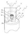
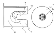
- FIG. 4 to 6 are views showing the positional relationship between the inlet 3a of the filter container 3 and the guide member 12.
- FIG. 4 first, in the initial stage, the filter container 3 is separated from the guide member 12.
- the filter container 3 is moved in the attaching direction X, and the inlet 3a of the filter container 3 is first attached to the holding portion 12a of the guide member 12. Fit (first state).
- the filter container 3 performs a translational movement with respect to the filter container attaching / detaching device.
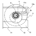
- the filter container 3 After fitting the inlet 3a of the filter container 3 to the holding portion 12a of the guide member 12, the filter container 3 is rotated around the second axis II (rotation in the fixing direction Y) according to the guide member 12. . Thereby, the guide member 12 moves from the first state to the second state. Along with the rotation, the flange 3 b gradually enters the clamping portion 11 c of the first pipe end 11. At this time, the filter container 3 rotates around the second axis II, but the first axis I and the second axis II are separated from each other by a predetermined distance, so that the flange 3b is relative to the first axis I. , It also rotates around the first axis I. In the case of FIGS.
- the filter container 3 rotates 90 degrees around the second axis II between the first state and the second state.
- an arbitrary point (point A in FIG. 5) of the flange 3b in the first state is the same as an arbitrary point (point A in FIG. 6) of the flange 3b in the second state with respect to the first state.
- the second axis II is also rotated 90 degrees
- the first axis I is also rotated 90 degrees.
- the flange 3b is in a second state in which it is completely clamped by the clamping part 11c of the first pipeline end part 11 (FIG. 6). The same applies to the third state and the fourth state.
- the rotation of the guide member 12 and the guide member 22 causes the joint surface 11b of the first pipe end 11 and the inflow port 3a of the filter container 3 to be in close contact with each other.
- the filter container can be easily attached and detached by reducing the frictional resistance while maintaining the close contact degree as compared with the case of translational operation. It becomes.
- FIGS. 7 and 8 are views corresponding to FIGS. 2 and 3 in the first embodiment, and show only one end portion of the filter container 3 and omit the other end portion of the filter container 3. Yes.
- the guide plate 4 is disposed at the inlet 3 a of the filter container 3.
- the guide plate 4 is held by the guide member holder 14 so as to be rotatable around the second axis II in the same manner as the guide member 12 is rotatable around the second axis II in the first embodiment.
- the second embodiment is the same as the first embodiment except that the guide plate 4 is fixed to the filter container 3.
Landscapes
- Chemical & Material Sciences (AREA)
- Chemical Kinetics & Catalysis (AREA)
- Filtration Of Liquid (AREA)
Abstract
La présente invention concerne un dispositif de montage/démontage sur lequel est monté de façon démontable un contenant de filtre doté en son sein d'un filtre et incluant une entrée ou une sortie de fluide, ladite entrée ou sortie faisant saillie à partir du contenant de filtre et incluant une bride. Le dispositif de montage/démontage comprend : une première section d'extrémité de passage de tube reliée à un premier passage de tube à travers lequel s'écoule le fluide, ladite première section d'extrémité de passage de tube incluant une section de préhension permettant de saisir la bride du contenant de filtre ; une surface de jonction pouvant venir en contact étroit avec l'entrée ou la sortie du contenant de filtre ; et un élément de guidage capable de tourner autour d'un second axe situé à une distance prédéfinie d'un premier axe s'étendant depuis le premier passage de tube vers l'entrée dans la direction qui s'étend depuis le premier passage de tube vers l'entrée ou la sortie, ledit élément de guidage incluant une section de retenue pouvant retenir l'entrée ou la sortie.
Priority Applications (5)
| Application Number | Priority Date | Filing Date | Title |
|---|---|---|---|
| JP2018501398A JP6683799B2 (ja) | 2016-02-26 | 2016-02-26 | フィルタ容器着脱システム |
| CN201680082452.6A CN108697952B (zh) | 2016-02-26 | 2016-02-26 | 过滤器容器装卸装置 |
| PCT/JP2016/001037 WO2017145196A1 (fr) | 2016-02-26 | 2016-02-26 | Système de montage/démontage de contenant de filtre |
| US16/079,938 US10744432B2 (en) | 2016-02-26 | 2016-02-26 | Filter vessel attachment/detachment apparatus |
| TW106106508A TWI640349B (zh) | 2016-02-26 | 2017-02-24 | Filter container handling system |
Applications Claiming Priority (1)
| Application Number | Priority Date | Filing Date | Title |
|---|---|---|---|
| PCT/JP2016/001037 WO2017145196A1 (fr) | 2016-02-26 | 2016-02-26 | Système de montage/démontage de contenant de filtre |
Publications (1)
| Publication Number | Publication Date |
|---|---|
| WO2017145196A1 true WO2017145196A1 (fr) | 2017-08-31 |
Family
ID=59684922
Family Applications (1)
| Application Number | Title | Priority Date | Filing Date |
|---|---|---|---|
| PCT/JP2016/001037 Ceased WO2017145196A1 (fr) | 2016-02-26 | 2016-02-26 | Système de montage/démontage de contenant de filtre |
Country Status (5)
| Country | Link |
|---|---|
| US (1) | US10744432B2 (fr) |
| JP (1) | JP6683799B2 (fr) |
| CN (1) | CN108697952B (fr) |
| TW (1) | TWI640349B (fr) |
| WO (1) | WO2017145196A1 (fr) |
Cited By (3)
| Publication number | Priority date | Publication date | Assignee | Title |
|---|---|---|---|---|
| JP2021035670A (ja) * | 2019-08-01 | 2021-03-04 | ポール・コーポレーションPall Corporation | マニホールドアセンブリ及び使用方法 |
| JP2021045743A (ja) * | 2019-09-17 | 2021-03-25 | ポール・コーポレーションPall Corporation | マニホールドアセンブリ及び使用方法 |
| JP2023543884A (ja) * | 2020-09-30 | 2023-10-18 | インテグリス・インコーポレーテッド | セルフロックマニホールド及びフィルタ |
Families Citing this family (4)
| Publication number | Priority date | Publication date | Assignee | Title |
|---|---|---|---|---|
| CN111467853B (zh) * | 2019-01-23 | 2022-08-02 | 杭州科百特过滤器材有限公司 | 一种用于固定过滤单元的夹具及其操作方法 |
| USD956923S1 (en) * | 2020-09-30 | 2022-07-05 | Entegris, Inc. | Filter connector |
| USD1004761S1 (en) * | 2022-01-07 | 2023-11-14 | Devin Ray BRIGHT | Four-stage filtration system |
| CN114570098B (zh) * | 2022-03-03 | 2024-05-17 | 长鑫存储技术有限公司 | 一种过滤器固定结构及过滤装置 |
Citations (4)
| Publication number | Priority date | Publication date | Assignee | Title |
|---|---|---|---|---|
| JPS53112490U (fr) * | 1977-02-15 | 1978-09-07 | ||
| JP2007253154A (ja) * | 2000-03-01 | 2007-10-04 | Mykrolis Corp | 分離ユニット |
| JP2012055873A (ja) * | 2010-09-13 | 2012-03-22 | Toyota Industries Corp | シリンジ濾過作業用補助具 |
| US20130228509A1 (en) * | 2010-11-19 | 2013-09-05 | Gokhan Kuruc | Filtration system |
Family Cites Families (6)
| Publication number | Priority date | Publication date | Assignee | Title |
|---|---|---|---|---|
| CN1082452A (zh) * | 1992-08-06 | 1994-02-23 | 奥于斯泰因·费斯特 | 流体过滤装置 |
| US5397462A (en) | 1993-08-24 | 1995-03-14 | Matsushita Electric Industrial Co., Ltd. | Filter with laterally removable element and valve means |
| DE19502020C2 (de) * | 1995-01-24 | 2002-02-28 | Mann & Hummel Filter | Flüssigkeitsfilter |
| DE19823765C1 (de) * | 1998-05-28 | 2000-02-03 | Dornier Gmbh Lindauer | Vorrichtung zur Großflächenfiltration thermoplastischer Schmelzen für Extruder |
| US9211488B2 (en) * | 2007-07-13 | 2015-12-15 | Cummins Filtration Ip, Inc. | Fluid filter with localized flow attachment |
| TWM419855U (en) * | 2011-07-01 | 2012-01-01 | Maxtec Plastics Inc | Easy-installation/uninstallation fixing structure of water filter |
-
2016
- 2016-02-26 CN CN201680082452.6A patent/CN108697952B/zh active Active
- 2016-02-26 WO PCT/JP2016/001037 patent/WO2017145196A1/fr not_active Ceased
- 2016-02-26 JP JP2018501398A patent/JP6683799B2/ja active Active
- 2016-02-26 US US16/079,938 patent/US10744432B2/en active Active
-
2017
- 2017-02-24 TW TW106106508A patent/TWI640349B/zh active
Patent Citations (4)
| Publication number | Priority date | Publication date | Assignee | Title |
|---|---|---|---|---|
| JPS53112490U (fr) * | 1977-02-15 | 1978-09-07 | ||
| JP2007253154A (ja) * | 2000-03-01 | 2007-10-04 | Mykrolis Corp | 分離ユニット |
| JP2012055873A (ja) * | 2010-09-13 | 2012-03-22 | Toyota Industries Corp | シリンジ濾過作業用補助具 |
| US20130228509A1 (en) * | 2010-11-19 | 2013-09-05 | Gokhan Kuruc | Filtration system |
Cited By (6)
| Publication number | Priority date | Publication date | Assignee | Title |
|---|---|---|---|---|
| JP2021035670A (ja) * | 2019-08-01 | 2021-03-04 | ポール・コーポレーションPall Corporation | マニホールドアセンブリ及び使用方法 |
| JP6992219B2 (ja) | 2019-08-01 | 2022-01-13 | ポール・コーポレーション | マニホールドアセンブリ及び使用方法 |
| JP2021045743A (ja) * | 2019-09-17 | 2021-03-25 | ポール・コーポレーションPall Corporation | マニホールドアセンブリ及び使用方法 |
| JP2023543884A (ja) * | 2020-09-30 | 2023-10-18 | インテグリス・インコーポレーテッド | セルフロックマニホールド及びフィルタ |
| JP7524472B2 (ja) | 2020-09-30 | 2024-07-29 | インテグリス・インコーポレーテッド | セルフロックマニホールド及びフィルタ |
| JP2024167179A (ja) * | 2020-09-30 | 2024-12-03 | インテグリス・インコーポレーテッド | セルフロックマニホールド及びフィルタ |
Also Published As
| Publication number | Publication date |
|---|---|
| TW201741012A (zh) | 2017-12-01 |
| TWI640349B (zh) | 2018-11-11 |
| US10744432B2 (en) | 2020-08-18 |
| JPWO2017145196A1 (ja) | 2018-12-13 |
| JP6683799B2 (ja) | 2020-04-22 |
| CN108697952B (zh) | 2021-01-08 |
| CN108697952A (zh) | 2018-10-23 |
| US20190054403A1 (en) | 2019-02-21 |
Similar Documents
| Publication | Publication Date | Title |
|---|---|---|
| JPWO2017145196A1 (ja) | フィルタ容器着脱システム | |
| JP6803404B2 (ja) | フィルタ容器着脱システム | |
| JP5429825B2 (ja) | コネクタアセンブリ、コネクタアセンブリを含む流体システム、および流体接続を行なうための手順 | |
| CN103209756B (zh) | 过滤系统 | |
| JP6803405B2 (ja) | フィルタ容器着脱システム | |
| CN103476474A (zh) | 一种过滤器组 | |
| JP6827413B2 (ja) | 交換ユニットおよびそれを用いた流れ回路システム | |
| JP2007504947A5 (fr) | ||
| TWI769980B (zh) | 交換單元安裝用岐管 | |
| JP6752198B2 (ja) | 交換ユニットおよびそれを用いた流れ回路システム | |
| CN110385859A (zh) | 管道连接用夹持夹具 | |
| JP5010882B2 (ja) | フィルタ付き迅速連結管継手 | |
| JP7098369B2 (ja) | フィルタ容器保持装置 | |
| CN204573196U (zh) | 高强度旋塞阀 | |
| CN113324101B (zh) | 一种便于拆卸的双pe管 | |
| CN220749356U (zh) | 快换接头结构 | |
| JP2005147398A5 (fr) | ||
| CN215110604U (zh) | 一种手动液动闸阀 | |
| KR20250095105A (ko) | 케미칼 필터조립체 | |
| JP2016022226A (ja) | 血液浄化回路パネル | |
| CN113680123A (zh) | 一种集成水路板及应用该集成水路板的过滤器 |
Legal Events
| Date | Code | Title | Description |
|---|---|---|---|
| WWE | Wipo information: entry into national phase |
Ref document number: 2018501398 Country of ref document: JP |
|
| NENP | Non-entry into the national phase |
Ref country code: DE |
|
| 121 | Ep: the epo has been informed by wipo that ep was designated in this application |
Ref document number: 16891359 Country of ref document: EP Kind code of ref document: A1 |
|
| 122 | Ep: pct application non-entry in european phase |
Ref document number: 16891359 Country of ref document: EP Kind code of ref document: A1 |