WO2017145205A1 - 像振れ補正装置、及び撮像装置 - Google Patents
像振れ補正装置、及び撮像装置 Download PDFInfo
- Publication number
- WO2017145205A1 WO2017145205A1 PCT/JP2016/004516 JP2016004516W WO2017145205A1 WO 2017145205 A1 WO2017145205 A1 WO 2017145205A1 JP 2016004516 W JP2016004516 W JP 2016004516W WO 2017145205 A1 WO2017145205 A1 WO 2017145205A1
- Authority
- WO
- WIPO (PCT)
- Prior art keywords
- magnets
- movable frame
- pair
- magnetic pole
- magnetic
- Prior art date
- Legal status (The legal status is an assumption and is not a legal conclusion. Google has not performed a legal analysis and makes no representation as to the accuracy of the status listed.)
- Ceased
Links
Images





Classifications
-
- G—PHYSICS
- G03—PHOTOGRAPHY; CINEMATOGRAPHY; ANALOGOUS TECHNIQUES USING WAVES OTHER THAN OPTICAL WAVES; ELECTROGRAPHY; HOLOGRAPHY
- G03B—APPARATUS OR ARRANGEMENTS FOR TAKING PHOTOGRAPHS OR FOR PROJECTING OR VIEWING THEM; APPARATUS OR ARRANGEMENTS EMPLOYING ANALOGOUS TECHNIQUES USING WAVES OTHER THAN OPTICAL WAVES; ACCESSORIES THEREFOR
- G03B5/00—Adjustment of optical system relative to image or object surface other than for focusing
Definitions
- the present disclosure relates to an image shake correction apparatus including an imaging element, and an imaging apparatus.
- an imaging apparatus having a mechanism for correcting the shake of an optical image at the time of imaging (hereinafter, referred to as an “image shake correction mechanism”) has been widely used for the purpose of acquiring a clear captured image.
- Such image shake correction mechanisms include an optical image shake correction mechanism and an image sensor drive type image shake correction mechanism.
- the optical image shake correction mechanism corrects and drives a part or all of the optical lens in a direction perpendicular to the optical axis or in a plane perpendicular to the optical axis (see, for example, Patent Document 1).
- the image sensor driving type image blur correction mechanism corrects and drives the image sensor in a plane perpendicular to the optical axis (see, for example, Patent Document 2).
- the present disclosure provides an image blur correction device that is effective for stably performing the image blur correction.
- An image shake correction apparatus is an image shake correction apparatus that corrects shake of an object image to be captured, and includes a movable frame, a fixed frame, a plurality of connecting members, a plurality of actuators, and a pair of magnets. And a magnetic body.
- the movable frame is displaceable along a plane orthogonal to the optical axis.
- the fixed frame faces the movable frame.
- the plurality of connecting members connect the fixed frame and the movable frame, and displaceably support the movable frame.
- the plurality of actuators change the position of the movable frame according to the displacement of the movable frame.
- the pair of magnets is provided on one of the fixed frame and the movable frame, and has a first magnetic pole and a second magnetic pole.
- the magnetic body is provided on the other of the fixed frame and the movable frame, and is disposed to face the pair of magnets.
- the magnetic body further has a plane facing the pair of magnets, and the plane has four sides. Of the four sides, the first side is disposed across the first magnetic pole and the second magnetic pole of the pair of magnets, and the second side intersecting the first side is one of the first magnetic pole and the second magnetic pole of the pair of magnets Arranged along.
- the first side is linear, and the second side is concave or convex intersecting the first side.
- the image shake correction device in the present disclosure is effective for stably performing the image shake correction.
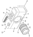
- FIG. 1 is a perspective view of a digital camera according to a first embodiment of the present disclosure.
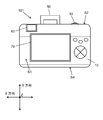
- FIG. 2 is a front view of the digital camera according to the first embodiment of the present disclosure.
- FIG. 3 is a front view of the image shake correction apparatus according to the first embodiment of the present disclosure.
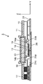
- FIG. 4 is a cross-sectional view taken along line 4-4 of FIG.
- FIG. 5 is a cross-sectional view taken along line 5-5 of FIG.
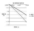
- FIG. 6 is a graph showing the relationship between the amount of movement of the odd-shaped suction plate and the amount of return force to the center position of the image shake correction apparatus according to the first embodiment of the present disclosure.
- FIG. 1 is a perspective view of a digital camera according to a first embodiment of the present disclosure.
- FIG. 2 is a front view of the digital camera according to the first embodiment of the present disclosure.
- FIG. 3 is a front view of the image shake correction apparatus according to the first embodiment of the present disclosure.
- FIG. 4 is a cross-section
- FIG. 7 is a graph showing the relationship between the amount of movement of the irregular suction plate and the rate of change in the amount of return force to the center position of the image shake correction apparatus according to Embodiment 1 of the present disclosure.
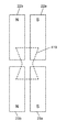
- FIG. 8A is a view showing a state in which the variant suction plate is displaced to one side with respect to the sensor magnet in the image shake correction apparatus according to the first embodiment of the present disclosure.
- FIG. 8B is a view showing a state in which the variant suction plate is at the center position with respect to the sensor magnet in the image shake correction apparatus according to Embodiment 1 of the present disclosure.
- FIG. 8A is a view showing a state in which the variant suction plate is displaced to one side with respect to the sensor magnet in the image shake correction apparatus according to the first embodiment of the present disclosure.
- FIG. 8B is a view showing a state in which the variant suction plate is at the center position with respect to the sensor magnet in the image shake correction apparatus according to Embodiment 1 of the present disclosure.
- FIG. 8C is a view showing a state in which the irregular suction plate is displaced to the other side with respect to the sensor magnet in the image shake correction apparatus according to the first embodiment of the present disclosure.
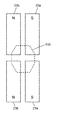
- FIG. 9A is a view showing a state in which a deformed suction plate according to a modification of the first embodiment of the present disclosure is displaced to one side with respect to the sensor magnet.
- FIG. 9B is a view showing a state in which a deformed suction plate according to a modification of the first embodiment of the present disclosure is at a central position with respect to the sensor magnet.
- FIG. 9C is a view showing a state in which the deformed suction plate according to the modification of the first embodiment of the present disclosure is displaced to the other side with respect to the sensor magnet.
- FIG. 9A is a view showing a state in which a deformed suction plate according to a modification of the first embodiment of the present disclosure is displaced to one side with respect to the sensor magnet.
- FIG. 9B is a view showing
- FIG. 10A is a view showing a modified suction plate according to another embodiment of the present disclosure.
- FIG. 10B is a view showing another modified suction plate according to another embodiment of the present disclosure.
- FIG. 10C is a view showing still another modified suction plate according to another embodiment of the present disclosure.
- An image pickup apparatus for example, a camera body
- an image pickup device drive type image shake correction mechanism has an image pickup element attached to a movable frame and displaceable two-dimensionally in a plane orthogonal to the optical axis together with the movable frame.
- the imaging device calculates the displacement direction and displacement amount of the imaging element in the plane from the output of the angular velocity sensor provided in the imaging device main body, and the subject of the imaging lens forms an image on the imaging element based on the calculated displacement amount. Correct the shake of the image.
- the displacement amount of the imaging device is a movement amount in the same plane from a reference position (a position in a state where the imaging device is not displaced) in a plane orthogonal to the optical axis.
- the drive device (actuator) of the imaging element includes a fixed frame and a movable frame.
- the movable frame is held by a rolling bearing constituted by at least three ball members. Therefore, a force (attracting force) is required to bias the movable frame to the fixed frame via the ball member.
- a force attracting force
- the spring force becomes strong according to the displacement amount of the imaging element, and not only the biasing force of the movable frame in the fixed frame direction but also the attraction force in the direction against the displacement direction. Furthermore, since a static spring can not be avoided between the movable frame and the fixed frame by the tension spring, the friction caused by the displacement of the movable frame greatly affects the drive control. On the other hand, when using magnetic attraction, contrary to the spring biasing, the attraction force becomes weak according to the displacement amount of the imaging element, and a force similar to a spring is generated in the displacement direction. Therefore, in either method, there is a problem that control of the actuator becomes very complicated.
- an imaging element driven two-dimensionally in a plane orthogonal to the optical axis of the photographing lens is stably attracted in the optical axis direction. Optimize the shape of the suction plate with respect to the magnet.
- a digital camera will be described as an example of the “imaging device”.
- “front”, “rear”, “upper”, “upper”, “lower”, “right”, and “left” are terms based on the imaging device in the horizontal shooting posture facing the subject, “front”
- the other side of the subject, that is, the photographer side is referred to as "rear”.
- FIG. 1 is a perspective view of a digital camera 100 according to the first embodiment of the present disclosure.
- FIG. 2 is a front view of the digital camera 100 according to the first embodiment of the present disclosure.
- the digital camera 100 includes a camera body 101 and a lens unit 200.
- the camera body 101 (an example of an imaging device) includes a housing 10, a body mount 20, a shutter button 30, a hot shoe 40, a flash light emitting unit 50, an electronic viewfinder 60, and a display device 70.
- the housing 10 accommodates the image blur correction device 1 (see FIG. 3) and the like.
- the housing 10 has a front surface S1, an upper surface S2, a rear surface S3 and a lower surface S4.
- the body mount 20 is provided on the front surface S1 of the housing 10.
- the lens unit 200 can be attached to the body mount 20 by bayonet coupling or the like.
- the body mount 20 has an opening 20 a centered on the optical axis AX of the lens unit 200. Incident light from the lens unit 200 is guided into the housing 10 through the opening 20 a.
- the shutter button 30 is provided on the top surface S2 of the housing 10. The shutter button 30 receives an opening / closing operation of the shutter by the user.
- the hot shoe 40 is provided on the top surface S2 of the housing 10.
- the hot shoe 40 can be mounted with a general-purpose external component (for example, a flash light emitting device or the like).
- the flash light emitting unit 50 is provided on the top surface S2 of the housing 10.
- the flash light emitting unit 50 can be housed in the housing 10. 1 and 2 show a state in which the flash light emitting unit 50 is pulled out of the case 10.
- the electronic viewfinder 60 is provided on the rear surface S3 of the housing 10.
- the electronic view finder 60 displays an image of a shooting range. The photographer can observe the image displayed on the electronic view finder 60.
- the display device 70 is provided on the rear surface S3 of the housing 10.
- the display device 70 displays an image of an imaging range, an operation menu, and the like.
- As the display device 70 for example, a liquid crystal display, an organic EL (Electro-Luminescence) display, an inorganic EL display, or the like can be used.
- the digital camera 100 includes a shutter unit (not shown), an image blur correction device 1 (FIG. 3), an imaging device 12 (FIG. 4), a circuit board 13 (FIG. 4), and a control circuit board (not shown). Etc.).
- the imaging device 12 is configured by, for example, a complementary metal oxide semiconductor (CMOS) image sensor, a charge-coupled device (CCD) image sensor, or the like.
- CMOS complementary metal oxide semiconductor
- CCD charge-coupled device
- the digital camera 100 shown in FIG. 1 is an example, and the form thereof is not limited to this.
- the interchangeable lens camera it may be a lens integrated camera or a single-lens reflex camera.
- a lens unit 200 (an example of an imaging apparatus) illustrated in FIG. 1 is an interchangeable lens unit, and a lens mount 201 mounted on the body mount 20 of the camera body 101, and a focus ring 202 that is an operation unit for driving a focus lens. , And a zoom ring 203 which is an operation unit for driving the zoom lens.
- the lens unit 200 further includes a lens controller, an optical system including a focus lens and a zoom lens, a focus lens drive unit, a zoom lens drive unit, a zoom ring, an aperture, an aperture drive unit, and a DRAM It includes a Random Access Memory), a flash memory, and the like.
- the optical image received by the imaging element 12 is converted into an electrical signal, that is, image data.
- the image data is subjected to a predetermined process (for example, AD (Analog / Digital) conversion) by the circuit board 13 which executes a predetermined program, and is further displayed on the display device 70 by the control circuit board (not shown).
- a predetermined process for example, AD (Analog / Digital) conversion
- FIG. 3 is a front view of the image shake correction apparatus 1 according to the first embodiment of the present disclosure.
- FIG. 4 is a cross-sectional view taken along line 4-4 of FIG.
- FIG. 5 is a cross-sectional view taken along line 5-5 of FIG.
- the image shake correction apparatus 1 according to the first embodiment will be described with reference to FIGS. 3, 4 and 5.
- the image shake correction apparatus 1 includes a drive mechanism that drives the imaging element 12.
- the image blur correction device 1 mainly includes the movable frame 11, the circuit board 13, the ball holding portions 110a, 110b, 110c, the drive coils 15, 16, 17, the drive magnets 25a and 25b. , 26b, 27a and 27b, magnetic displacement detection sensors 14a, 14b and 14c, sensor magnets 22a and 22b, 23a and 23b, 24a and 24b, a modified suction plate 19 and a fixed holding member 21.
- the circuit board 13, the ball holding portions 110 a, 110 b, 110 c, the drive coils 15, 16, 17, the magnetic displacement detection sensors 14 a, 14 b, 14 c and the deformed suction plate 19 are attached to the movable frame 11.
- the drive magnets 25a and 25b, 26b, 27a and 27b, the sensor magnets 22a and 22b, 23a and 23b, and 24a and 24b are attached to the fixed holding member 21.
- the movable frame 11 (an example of the movable frame) holds the imaging device 12 and is disposed to face the fixed holding member 21.
- the circuit board 13 is electrically connected to the imaging device 12 and converts an electrical signal from the imaging device 12 from an analog signal to a digital signal.
- the movable frame 11 movably holds the imaging element 12 in the direction orthogonal to the optical axis AX.
- the ball holding portions 110a, 110b, and 110c hold ball members 31a, 31b, and 31c (an example of a connecting member) that connect the movable frame 11 and the fixed holding member 21.
- the ball members 31 a, 31 b, 31 c support the movable frame 11 movably with respect to the fixed holding member 21. Details of the ball holding portions 110a, 110b, and 110c will be described later.
- the three drive coils 15, 16, 17 are adhesively fixed to the movable frame 11.
- the terminals of each drive coil are soldered to the circuit board 13 electrically connected to the imaging device 12.
- the terminals of each drive coil are fed from the circuit board 13.
- the drive magnets 26 b and 27 a and the pair of drive magnets 27 a and 27 b disposed to face the drive coil 17 in the optical axis direction constitute an actuator (an example of an actuator) for driving the imaging device 12.
- the drive magnets 25a, 27a are magnetized to the S pole on the side facing the drive coils 15, 16, 17.
- the drive magnets 25b, 26b, 27b are drive coils 15, 16, 17 It is magnetized to the N pole on the side opposite to.
- Three magnetic displacement detection sensors 14 a, 14 b, 14 c are disposed on the circuit board 13.
- the magnetic displacement detection sensors 14a, 14b, 14c are configured by, for example, Hall elements.
- Sensor magnets 22a and 22b, 23a and 23b, 24a and 24b which face the magnetic displacement detection sensors 14a, 14b and 14c, respectively, on the fixed holding member 21 facing the magnetic displacement detection sensors 14a, 14b and 14c. (An example of a plurality of pairs of magnets) is provided.
- the magnetic displacement detection sensors 14 a, 14 b, 14 c and the sensor magnets 22 a and 22 b, 23 a and 23 b, 24 a and 24 b detect the displacement of the imaging element 12.
- the sensor magnets 22a, 23a, 24a are magnetized on the S pole (an example of one of the first magnetic pole and the second magnetic pole) on the side facing the movable frame 11, and the sensor magnets 22b, 23b, 24b are mounted on the movable frame 11.
- the N pole (the other example of the first magnetic pole and the second magnetic pole) is magnetized on the opposite side.
- the variant suction plate 19 (an example of a magnetic body) has a rectangular shape made of a magnetic body such as a metal plate, and is disposed so that the four sides thereof coincide with the X-axis direction and the Y-axis direction. Of the four sides of the odd-shaped suction plate 19, a pair of opposing sides is a concave arc.
- the variant suction plate 19 is disposed on the movable frame 11 opposed to the sensor magnets 22a and 22b (an example of a first pair of magnets) and 23a and 23b (an example of a second pair of magnets).
- the deformed suction plate 19 attracts the movable frame 11 toward the fixed holding member 21 using the magnetic force of the sensor magnets 22a, 22b, 23a, 23b.
- the ball members 31a, 31b, 31c held by the ball holding portions 110a, 110b, 110c described later can be biased toward the fixed holding member 21 side.
- the fixed holding member 21 (an example of a fixed frame) is fixed to a support frame (not shown) in the camera body 101.
- the imaging device 12 driven by the drive mechanism is fixed to the movable frame 11 by adhesion or the like.
- the imaging element 12 is electrically connected to the circuit board 13.
- the movable frame 11 is provided with three ball holding portions 110a, 110b and 110c which are rectangular in a plan view.
- Each of the ball holding portions 110a, 110b, and 110c is formed by a surface on which the ball members 31a, 31b, and 31c abut (hereinafter, referred to as a ball contact surface) is orthogonal to the optical axis AX.
- a ball contact surface On each ball contact surface, movable metal plates 111a, 111b, and 111c having a smooth surface and having as little magnetism as possible are disposed.
- the ball members 31a, 31b, 31c are made of, for example, a rigid nonmetallic material such as zirconia.
- the fixed holding member 21 has a surface substantially orthogonal to the optical axis AX at a position facing the ball members 31a, 31b, 31c, and the surface is smooth.
- Fixed metal plates 28a, 28b and 28c having as little magnetism as possible are fixed to the fixed holding member 21 by adhesion or the like.
- the actuator is composed of drive coils 15, 16, 17 described below, and drive magnets 25a and 25b, 27a and 26b, and 27a and 27b.
- the actuator can correct the image blur due to the movement of the camera body 101 by changing the position of the movable frame 11.
- Three pairs of drive magnets 25a and 25b, 27a and 26b, and 27a and 27b are disposed on the fixed holding member 21 disposed on the rear surface side of the imaging device 12 so as to face each of the drive coils 15, 16 and 17, respectively. It is done.
- Each drive coil 15, 16 and 17 moves from a central position relative to the corresponding one of the three pairs of drive magnets 25a and 25b, 27a and 26b, 27a and 27b, depending on the feeding direction from the circuit board 13. It will be done.
- the reason why there are three drive coils is to rotationally drive around the illustrated Z axis in a plane orthogonal to the optical axis AX.
- the drive coil 15 is supplied with power to be driven in the X + direction (the arrow direction of X) shown in FIG. 3, and the drive coil 16 is supplied with power to be driven in the X ⁇ direction.
- the center of rotation can be determined according to the amount and direction of power supplied to the drive coil 17.
- the drive coil 15 and the drive coil 16 are fed in the same direction of phase to drive in the yaw direction, and the drive coil 17 is fed in the pitch direction. Driving is possible.
- the displacement detection mechanism is composed of magnetic displacement detection sensors 14a, 14b and 14c and sensor magnets 22a and 22b, 23a and 23b, 24a and 24b described below.
- Magnetic displacement detection sensors 14a, 14b, and 14c are disposed at three locations on the rear surface side (opposite side of the object) of the imaging element 12 of the circuit board 13. Each detects the displacement of at least one of the imaging elements 12 in the yaw direction and the pitch direction. Another magnetic displacement detection sensor is disposed in either the yaw direction or the pitch direction. In the present embodiment, the magnetic displacement detection sensors 14a and 14b are disposed at two locations for detecting the yaw direction, and the magnetic displacement detection sensor 14c is disposed at one location for detecting the pitch direction.
- an intermediate point C of a line connecting the two magnetic displacement detection sensors 14a and 14b for detecting the yaw direction is approximately the center position of the imaging element 12 in forming a magnetic attraction mechanism described later.
- a pair of sensor magnets 22a and 22b, a pair of sensor magnets 23a and 23b, and a pair of sensor magnets 24a and 24b are respectively disposed at positions corresponding to the magnetic displacement detection sensors 14a, 14b and 14c. It is arranged.
- the three pairs of sensor magnets 22a and 22b, 23a and 23b, and 24a and 24b are fixed to a sensor magnet yoke plate 29 fixed to the fixed holding member 21 as shown in FIG. 4 by adhesion or the like.
- the sensor magnets 22 a and 22 b, 23 a and 23 b, 24 a and 24 b are disposed in the hole 21 c provided in the fixed holding member 21. This is to secure a space for the magnetic attraction mechanism described later, and the sensor magnets 22a and 22b, 23a and 23b, 24a and 24b may be directly fixed to the fixed holding member 21 if the space is sufficient.
- the displacement detection mechanism described above can accurately detect the displacement of the imaging device 12 at least in the yaw direction, the pitch direction, and the roll direction.
- the magnetic attraction mechanism is composed of a variant attraction plate 19 described below, and sensor magnets 22a and 22b, and 23a and 23b.
- the ball members 31a, 31b, and 31c may fall off if the imaging device 12 is not always pressed in the direction of the fixed holding member 21, and smooth drive by rolling may not be possible.
- the variant attraction plate 19 and the sensor are made use of the magnetic force to the side facing the magnetic displacement detection sensors 14a, 14b and 14c by the sensor magnets 22a and 22b, 23a and 23b, 24a and 24b.
- a suction force is applied between the magnets 22a and 22b and 23a and 23b.
- the deformed suction plate 19 is fixed to the holding member 18 attached to the movable frame 11 by adhesion or the like.
- the variant suction plate 19 is held at the center position in the movable range of the imaging device 12 and in the plane where the center of the variant suction plate 19 is orthogonal to the optical axis AX, the sensor magnets 22a, 22b, 23a, 23b It is disposed so as to coincide with the center C of the enclosed gap, and to align the yaw direction and the pitch direction with the four sides of the odd-shaped suction plate 19.
- the image pickup element 12, the circuit board 13, the magnetic displacement detection sensors 14a, 14b, 14c, the holding member 18, the variant suction plate 19, the sensor magnets 22a and 22b, 23a and 23b, 24a and 24b are arranged in the optical axis AX direction. It is arranged in order.
- These members are fixed to the movable frame 11 by screw fastening or the like. With this configuration, suction by the odd-shaped suction plate 19 is possible substantially at the center of the imaging device 12, that is, near the optical axis AX. Therefore, a stable suction force can be maintained even when the imaging element 12 is displaced.
- the movement restricting mechanism is constituted by restricting shafts 112 and 113 and restricting holes 21a and 21b described below.
- the imaging element 12 is displaced, and the ball members 31a, 31b, and 31c are the standing walls 119 (FIG. 5) of the rectangular ball holding portions 110a, 110b, and 110c.
- the standing wall 119 is a surface substantially parallel to the optical axis AX surrounding the ball members 31a, 31b, and 31c among the surfaces forming the ball holding portions 110a, 110b, and 110c.
- the frictional load is a variable factor to the driving force of the actuator, which makes accurate image blur correction control difficult.
- an unexpected impact or the like is applied, there is a concern that the ball members 31a, 31b, and 31c may fall over the standing wall 119.
- the limiting shafts 112 and 113 supported by the holding member 18 are provided.
- the restriction shafts 112 and 113 are provided in restriction holes 21 a and 21 b provided in the fixed holding member 21.
- the restriction shafts 112 and 113 have buffer rings 112a and 113a so that no noise is generated when the restriction shafts 112 and 113 abut on the walls of the restriction holes 21a and 21b.
- the restriction shafts 112 and 113 abut on the end faces of the restriction holes 21a and 21b via the buffer rings 112a and 113a.
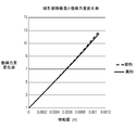
- FIG. 6 is a graph showing the relationship between the amount of movement of the variant suction plate 19 and the amount of return force to the center position of the image shake correction apparatus 1 according to Embodiment 1 of the present disclosure.
- the graph of FIG. 6 shows the relationship between the displacement amount (movement amount) of the suction plate and the return force in the direction orthogonal to the optical axis AX.
- the suction plate has a rectangular suction plate having a size of 8 mm ⁇ 7 mm (a quadrilateral with all corners at right angles) and an 8 mm suction plate concaved in an arc shape of 1.5 mm.
- 19 shows the result of comparison with 19 (FIG. 3).
- the deformed suction plate 19 has a smaller change in return force relative to the change in movement than the rectangular suction plate. From this, even if the deformed suction plate 19 fixed to the movable frame 11 is largely displaced with respect to the sensor magnets 22a and 22b and 23a and 23b attached to the fixed holding member 21 in the image blur correction operation, The change in suction force by the odd-shaped suction plate 19 is small. Thereby, the suction force by the magnetic attraction mechanism according to the present embodiment can be stably obtained, and the ball holding portions 110a, 110b, 110c can hold the ball members 31a, 31b, 31c more stably. Become. As a result, the image blur correction operation can be stably performed.
- FIG. 7 is a graph showing the relationship between the amount of movement of the irregular suction plate and the rate of change in the amount of return force to the center position of the image shake correction apparatus according to Embodiment 1 of the present disclosure.
- the graph of FIG. 7 shows the relationship between the displacement amount (movement amount) of the suction plate and the rate of change of the return force. From this graph, it can be seen that the rate of change in return force changes more linearly in the deformed shape. That is, it is understood that voltage control calculation for the displacement amount is easier in the change control of the feed.
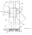
- FIG. 8A is a view showing a state in which the odd-shaped attraction plate 19 is displaced to one side with respect to the sensor magnets 22a and 22b and 23a and 23b in the image shake correction apparatus 1 according to the first embodiment of the present disclosure.
- FIG. 8B is a view showing a state in which the odd-shaped suction plate 19 is at the center position with respect to the sensor magnets 22a and 22b and 23a and 23b in the image shake correction apparatus 1.
- FIG. 8C is a view showing a state in which the odd-shaped suction plate 19 is displaced to the other side with respect to the sensor magnets 22a and 22b and 23a and 23b in the image shake correction apparatus 1.
- FIG. 8B shows a state in which the deformed suction plate 19 is in the magnetic equilibrium position.
- the deformed suction plate 19 has a line-symmetrical shape, and has a flat surface facing the sensor magnets 22a, 22b, 23a, 23b.
- the straight side 19L1 (an example of the first side) is disposed across the sensor magnet 22a of the S pole and the sensor magnet 22b of the N pole.
- a linear side 19L3 (an example of a third side) facing the side 19L1 is disposed across the sensor magnet 23a of the S pole and the sensor magnet 23b of the N pole.
- a concave side 19L2 (an example of a second side) intersecting the side 19L1 is disposed across the N pole sensor magnet 22b and the N pole sensor magnet 23b.
- a side 19L4 (an example of a fourth side) facing the side 19L2 is disposed across the sensor magnet 22a of the S pole and the sensor magnet 23a of the S pole.
- the suction plate When the suction plate has a rectangular shape, when the displacement of the suction plate increases, the suction force in the direction of the optical axis AX rapidly attenuates, and returns to the magnetic equilibrium position (intermediate point C shown in FIG. 3 in this embodiment) The force in the direction orthogonal to the optical axis AX to be moved sharply increases.
- the suction force is generated in proportion to the area of the suction plate, but its displacement increases the leakage flux in the thickness direction of the suction plate, thereby increasing the suction force to the magnet on one side, and the leakage flux by the other magnet It becomes smaller and suction power decreases.
- FIG. 8A shows the case where the suction plate is displaced to the X + side.
- the suction plate is a rectangular suction plate
- the end face of the side VL2 on the X + side is located near the end faces of the sensor magnets 22b and 23b. Therefore, the leakage flux MF1n acting on the end face of the side VL2 is smaller than the leakage flux MF1s acting on the end face of the side VL4 opposite to the side VL2. Therefore, due to the difference in suction force described above, a force that returns in the X-direction acts on the suction plate.
- the end face of the side 19L2 on the X + side is located near the end faces of the sensor magnets 22b and 23b, but since it is concave, compared to the case of the rectangular suction plate The leakage flux MF1n acting on the end face of the side 19L2 is large. Thus, the return force in the X-direction due to the suction difference is relatively small.
- FIG. 8C shows the case where the suction plate is displaced to the X-side.
- the suction plate is a rectangular suction plate
- the end face of the side VL4 on the X- side is located near the end faces of the sensor magnets 22a and 23a. Therefore, the leakage flux MF1s acting on the end face of the side VL4 is smaller than the leakage flux MF1n acting on the end face of the side VL2 facing the VL4.
- a force that returns in the X + direction acts on the suction plate.
- the end face of the side 19L4 on the X- side is located near the end faces of the sensor magnets 22a and 23a, but since it is concave, compared to the case of the rectangular suction plate.
- the leakage flux MF1s acting on the end face of the side 19L3 is large. Accordingly, the return force in the X + direction due to the suction difference is relatively small.
- the attraction force in the direction of the optical axis AX is damped in the same manner as the rectangular suction plate.
- the change of the force in the direction orthogonal to the optical axis AX that is going to return to the magnetic equilibrium position is small.
- the suction force is generated in proportion to the area of the variant suction plate 19, so the displacement of the variant suction plate 19 increases the leakage flux in the thickness direction of the variant suction plate 19.
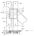
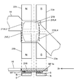
- FIG. 9A is a view showing a state in which a deformed suction plate 219 according to a modification of the first embodiment of the present disclosure is displaced to one side with respect to the sensor magnets 22a, 22b, 23a, 23b.
- FIG. 9B is a view showing a state in which the odd-shaped attraction plate 219 is at a central position with respect to the sensor magnets 22a, 22b, 23a, 23b.
- FIG. 9C is a view showing a state in which the odd-shaped attraction plate 219 is displaced to the other side with respect to the sensor magnets 22a, 22b, 23a, 23b.
- the shape of the odd-shaped suction plate 219 may be a convex arc shape.
- FIG. 9B shows a state in which the variant suction plate 219 according to this modification is at the magnetic equilibrium position.
- the deformed suction plate 219 has a flat surface facing the sensor magnets 22a, 22b, 23a, 23b.
- the straight side 219L1 (an example of the first side) is disposed across the sensor magnet 22a of the S pole and the sensor magnet 22b of the N pole.
- a linear side 219L3 (an example of a third side) facing the side 219L1 is disposed across the sensor magnet 23a of the S pole and the sensor magnet 23b of the N pole.
- a convex side 219L2 (an example of a second side) intersecting the side 219L1 is disposed across the N pole sensor magnet 22b and the N pole sensor magnet 23b.
- a side 219L4 (an example of a fourth side) facing the side 219L2 is disposed across the sensor magnet 22a of the S pole and the sensor magnet 23a of the N pole.
- FIG. 9A shows a case where the suction plate according to this modification is displaced to the X + side.
- the suction plate is a rectangular suction plate
- the end face of the side 2VL2 on the X + side is located near the end faces of the sensor magnets 22b and 23b. Therefore, the leakage flux MF1n acting on the end face of the side 2VL2 is smaller than the leakage flux MF1s acting on the end face of the side 2VL4 facing the 2VL2. Therefore, due to the difference in suction force described above, a force that returns in the X-direction acts on the suction plate.
- the end face of the side 219L2 on the X + side is located near the end faces of the sensor magnets 22b and 23b, but since it is convex, compared to the case of the rectangular suction plate.
- the leakage flux MF1n acting on the end face of the side 219L2 is large.
- the return force in the X-direction due to the suction difference is relatively small.
- FIG. 9C shows the case where the suction plate is displaced to the X-side.
- the suction plate is a rectangular suction plate
- the end face of the side 2VL4 on the X ⁇ side is located near the end faces of the sensor magnets 22a and 23a. Therefore, the leakage flux MF1s acting on the end face of the side 2VL4 is smaller than the leakage flux MF1n acting on the end face of the side 2VL2 facing the 2VL4.
- a force that returns in the X + direction acts on the suction plate.
- the end face of the side 219L4 on the X- side is located near the end faces of the sensor magnets 22a and 23a, but since it is convex, compared to the case of the rectangular suction plate.
- the leakage flux MF1s acting on the end face of the side 219L4 is large. Accordingly, the return force in the X + direction due to the suction difference is relatively small.
- the image shake correction apparatus 1 is an image shake correction apparatus that corrects shake of a subject image to be picked up, and includes a fixed frame corresponding to the fixed holding member 21, a movable frame 11, and a plurality of ball members. 31a, 31b, 31c, a plurality of coupling members corresponding to 31a, 31b, 31c, a plurality of actuators corresponding to drive coils 15, 16, 17 and drive magnets 25a and 25b, 27a and 26b, 27a and 27b, sensor magnets 22a, 22b, 23a , And 23b, and a magnetic body corresponding to the odd-shaped suction plates 19 and 219.
- the movable frame 11 is displaceable along a plane orthogonal to the optical axis.
- the fixed frame faces the movable frame 11.
- the plurality of connecting members corresponding to the ball members 31a, 31b, and 31c connect the fixed frame corresponding to the fixed holding member 21 and the movable frame 11, and support the movable frame 11 so as to be displaceable.
- a plurality of actuators corresponding to the drive coils 15, 16, 17 and the drive magnets 25a and 25b, 27a and 26b, 27a and 27b change the position of the movable frame 11 according to the displacement of the movable frame 11.
- a pair of magnets corresponding to the sensor magnets 22a, 22b, 23a, 23b are provided on one of the fixed frame corresponding to the fixed holding member 21 and the movable frame 11, and correspond to the first magnetic pole and the N pole corresponding to the S pole. It has a second magnetic pole.
- a magnetic body corresponding to the deformed suction plate 19, 219 is provided on the other of the fixed frame corresponding to the fixed holding member 21 and the movable frame 11, and faces a pair of magnets corresponding to the sensor magnets 22a, 22b, 23a, 23b. Arranged as.
- the magnetic body corresponding to the deformed suction plate 19 219 has a flat surface facing the pair of magnets corresponding to the sensor magnets 22a 22b 23a 23b, and the flat surface has four sides. Of the four sides, the first sides 19L1 and 219L1 are disposed across the first magnetic pole corresponding to the S pole of the pair of magnets corresponding to the sensor magnets 22a and 22b and the second magnetic pole corresponding to the N pole. The second sides 19L2 and 219L2 intersecting 19L1 and 219L1 are disposed along one of the first magnetic pole corresponding to the S pole of the pair of magnets corresponding to the sensor magnets 22b and 23b and the second magnetic pole corresponding to the N pole . The first sides 19L1 and 219L1 are linear, and the second sides 19L2 and 219L2 are concave or convex intersecting the first sides 19L1 and 219L1.
- the variant suction plates 19 and 2119 are large as shown in FIG. 8A or 9A, for example, the variant suction plates 19 or 219.
- the leakage flux in the thickness direction of the magnetic sensor increases, the attractive force to the sensor magnet 22a or 23a on one side increases.
- the decrease in the leakage flux due to the sensor magnets 22b and 23b on the other side is suppressed. For this reason, the difference in suction force according to the displacement amount of the odd-shaped suction plates 19 and 219 is small.
- each of the pair of magnets corresponding to the sensor magnets 22a, 22b, 23a, 23b has a first magnetic pole corresponding to the S pole and a second magnetic pole corresponding to the N pole.
- a plurality of pairs of magnets corresponding to 22a, 22b, 23a, 23b may be provided.
- the sensor magnets 22a, 22b, 23a are provided on the other of the fixed frame and the movable frame 11 corresponding to the fixed holding member 21 so as to face a plurality of pairs of magnets corresponding to the sensor magnets 22a, 22b, 23a, 23b.
- 23b may be provided with a plurality of displacement detection units corresponding to the magnetic displacement detection sensors 14a, 14b, 14c for detecting the displacement of the movable frame 11 based on changes in the magnetic flux of a plurality of pairs of magnets corresponding to 23b.
- the movable frame 11 displacement detection units corresponding to the magnetic displacement detection sensors 14a, 14b and 14c, magnetic bodies corresponding to the odd-shaped attraction plates 19 and 219, sensor magnets 22a and 22b, 23a and 23b, 24a and 24b.
- the pair of magnets may be arranged in this order along the optical axis direction.
- the magnetic substance corresponding to the odd-shaped suction plate 19 or 219 is attracted to a pair of magnets corresponding to the sensor magnets 22a, 22b, 23a and 23b, thereby the movable frame 11 is equivalent to the ball members 31a, 31b and 31c. May be arranged to be pressed against the connecting member.
- the connecting members corresponding to the ball members 31 a, 31 b, and 31 c can be biased toward one side of the fixed frame corresponding to the fixed holding member 21 and the movable frame 11.
- the third sides 19L3 and 219L3 opposed to the first sides 19L1 and 219L1 among the four sides are the S poles of a pair of magnets corresponding to the sensor magnets 23a and 23b.
- the fourth sides 19L4 and 219L4 disposed across the corresponding first magnetic pole and the second magnetic pole corresponding to the N pole and facing the second sides 19L2 and 219L2 correspond to the sensor magnets 22a, 22b, 23a, and 23b.
- the third sides 19L3 and 219L3 are linear, and the fourth sides 19L4 and 219L4 are the fourth It may be concave or convex intersecting with the three sides 19L3 and 219L3.
- the movable imaging element 12 in the image blur correction function can be stably attracted in the optical axis AX direction. Therefore, control of the image blur correction drive actuator becomes easy. Therefore, image blur correction with higher performance can be performed.
- displacement detection units corresponding to the magnetic displacement detection sensors 14a, 14b and 14c detect the displacement amount and displacement direction of the movable frame 11, and drive coils 15, 16 and 17 and drive magnets 25a and 25b, 27a and 26b,
- the actuators corresponding to 27a and 27b may change the position of the movable frame 11 according to the detected displacement amount and displacement direction of the movable frame 11. Thereby, it is possible to correct the image blur due to the movement of the camera body 101.
- the planar shape of the magnetic body corresponding to the odd-shaped suction plate 19 or 219 may be line symmetrical.
- the movable imaging element 12 in the image blur correction function can be stably attracted in the optical axis AX direction. Therefore, control of the image blur correction drive actuator becomes easy. Therefore, image blur correction with higher performance can be performed.
- the image shake correction apparatus 1 is an image shake correction apparatus that corrects shake of an object image to be captured, and includes a fixed frame corresponding to the fixed holding member 21, a movable frame 11, and a plurality of A plurality of connection members corresponding to the ball members 31a, 31b and 31c, a plurality of actuators corresponding to the drive coils 15, 16 and 17 and the drive magnets 25a and 25b, 27a and 26b, 27a and 27b, and sensor magnets 22a and 22b , A pair of magnets corresponding to 23a and 23b, and a magnetic body corresponding to the odd-shaped attraction plates 19 and 219.
- the movable frame 11 is displaceable along a plane orthogonal to the optical axis.
- the fixed frame faces the movable frame 11.
- the plurality of connecting members corresponding to the ball members 31a, 31b, and 31c connect the fixed frame corresponding to the fixed holding member 21 and the movable frame 11, and support the movable frame 11 so as to be displaceable.
- a plurality of actuators corresponding to the drive coils 15, 16, 17 and the drive magnets 25a and 25b, 27a and 26b, 27a and 27b change the position of the movable frame 11 according to the displacement of the movable frame 11.
- a pair of magnets corresponding to the sensor magnets 22a, 22b, 23a, 23b are provided on one of the fixed frame corresponding to the fixed holding member 21 and the movable frame 11, and correspond to the first magnetic pole and the N pole corresponding to the S pole.
- a magnetic body corresponding to the deformed suction plate 19, 219 is provided on the other of the fixed frame corresponding to the fixed holding member 21 and the movable frame 11, and faces a pair of magnets corresponding to the sensor magnets 22a, 22b, 23a, 23b.
- the pair of magnets corresponding to the sensor magnets 22a, 22b, 23a, 23b includes a first pair of magnets corresponding to the sensor magnets 22a, 22b and a second pair of magnets corresponding to the sensor magnets 23a, 23b.
- the magnetic body corresponding to the deformed suction plate 19 219 has a flat surface facing the first pair of magnets corresponding to the sensor magnets 22a 22b and the second pair of magnets corresponding to the sensor magnets 23a 23b, and the flat surface is It has four sides. Of the four sides, the first sides 19L1 and 219L1 are disposed across the first magnetic pole corresponding to the S pole of the first pair of magnets corresponding to the sensor magnets 22a and 22b and the second magnetic pole corresponding to the N pole. .
- the second sides 19L2 and 219L2 intersecting the first sides 19L1 and 219L1 correspond to the first magnetic pole corresponding to the S pole of the first pair of magnets corresponding to the sensor magnets 22a and 22b and the second magnetic pole corresponding to the sensor magnets 23a and 23b. It is disposed across the first magnetic pole corresponding to the south pole of the pair of magnets.
- the first sides 19L1 and 219L1 are linear, and the second sides 19L2 and 219L2 are concave or convex intersecting the first sides 19L1 and 219L1.
- the movable imaging element 12 in the image blur correction function can be stably attracted in the optical axis AX direction. Therefore, control of the image blur correction drive actuator becomes easy. Therefore, image blur correction with higher performance can be performed.
- the third sides 19L3 and 219L3 of the four sides facing the first sides 19L1 and 219L1 are S of the second pair of magnets corresponding to the sensor magnets 23a and 23b. It is disposed across between the first magnetic pole corresponding to the pole and the second magnetic pole corresponding to the N pole.
- the fourth sides 19L4 and 219L4 facing the second sides 19L2 and 219L2 are a second magnetic pole corresponding to the N pole of the first pair of magnets corresponding to the sensor magnets 22a and 22b and a second magnetic pole corresponding to the sensor magnets 23a and 23b. It is disposed across the second magnetic pole corresponding to the N pole of the pair of magnets.
- the third sides 19L3 and 219L3 are linear, and the fourth sides 19L4 and 219L4 are concave or convex intersecting the third sides 19L3 and 219L3.
- the movable imaging element 12 in the image blur correction function can be stably attracted in the optical axis AX direction. Therefore, control of the image blur correction drive actuator becomes easy. Therefore, image blur correction with higher performance can be performed.
- a plurality of connecting members corresponding to the ball members 31a, 31b and 31c, a plurality of actuators corresponding to the drive coils 15, 16 and 17 and the drive magnets 25a and 25b, 27a and 26b, 27a and 27b, the magnetic displacement detection sensor 14a , 14b, and 14c, and three or more pairs of magnets corresponding to the sensor magnets 22a, 22b, 23a, and 23b may be provided.
- the imaging device corresponding to the digital camera 100 of the present embodiment may include the image shake correction device 1 and the imaging element 12 for converting an optical image of a subject into an electrical signal.
- the movable frame 11 may hold the imaging element 12 so as to be displaceable along the facing surface of the movable frame 11. As a result, it is possible to provide an imaging apparatus having a higher performance image blur correction function.
- an imaging device corresponding to the digital camera 100 may include the image shake correction device 1 and a plurality of optical systems for condensing light from a subject.
- the movable frame 11 may hold one of the plurality of optical systems so as to be displaceable along the facing surface of the movable frame 11. As a result, it is possible to provide an imaging apparatus having a higher performance image blur correction function.
- Embodiment 1 has been described as an example of the technology in the present disclosure.
- the technology in the present disclosure is not limited to this, and can be applied to embodiments in which changes, replacements, additions, omissions, and the like have been made.
- the shape of the odd-shaped suction plates 19 and 219 in the first embodiment is not limited to the arc shape. The same effect can be obtained if the shape of the deformed suction plates 19 and 219 is concave or convex with respect to the direction in which the return force of the deformed suction plates 19 and 219 acts.
- FIG. 10A is a view showing a modified suction plate according to another embodiment of the present disclosure.
- FIG. 10B is a view showing another modified suction plate according to another embodiment of the present disclosure.
- FIG. 10C is a view showing still another modified suction plate according to another embodiment of the present disclosure.
- the shape of the deformed suction plates 19 and 219 is, for example, an uneven suction plate including a straight line in part as in the deformed suction plate 319 shown in FIG. 10A, the deformed suction plate 419 shown in FIG. 10B, and the deformed suction plate 519 shown in FIG. It may be shaped.
- the image sensor driving type image shake correction device has been described as an example, but the image shake correction device according to the present disclosure is also applicable to a lens shift method.
- a plurality of modified suction plates are fixed on the circumferential surface of a doughnut-shaped lens frame (movable frame) holding an image blur correction lens at the center, and sensor magnets are installed at the opposing doughnut-shaped fixed frame positions Do.
- the image shake correction apparatus when the movable frame is displaced in the direction perpendicular to the optical axis with respect to the fixed frame, the force of the movable frame being returned to the magnetic equilibrium position can be suppressed by the action of the odd-shaped attraction plate. As a result, stable image blur correction can be performed.
- the displacement in the X direction of the deformed suction plates 19 and 219 is taken as an example, but the displacement can also be applied to the displacement in the Y direction.
- the arrangement of the variant suction plates 19 and 219 and the sensor magnets 22a, 22b, 23a and 23b in the X direction shown in FIGS. 8A to 8C and 9A to 9C may be the arrangement in the Y direction.
- the sensor magnets facing the variant suction plates 19, 219 may be a pair of sensor magnets.
- the pair of sensor magnets have an S pole and an N pole.
- the deformed suction plates 19 and 219 have flat surfaces facing the pair of sensor magnets.
- the linear first side, the opposing third side, or both the first side and the third side are disposed across the S pole and the N pole.
- the concave or convex second side intersecting the first side, or the opposing fourth side, or both the second side and the fourth side are disposed along the N pole or the S pole.
- the deformed suction plates 19 and 219 are arranged such that their centers are aligned along the optical axis at the midpoint between the pair of magnets.
- the sensor magnets 22 a, 22 b, 23 a, 23 b, 24 a, 24 b are disposed on the fixed holding member 21, but may be disposed on the movable frame 11.
- at least the corresponding magnetic displacement detection sensors 14 a, 14 b, 14 c and the odd-shaped suction plates 19, 219 are disposed on the fixed holding member 21.
- the digital camera 100 shown to FIG. 1 and FIG. 2 was mentioned as an example of a digital camera, it is not limited to this. It may be any camera system that can be equipped with an image shake correction device using either a sensor shift method or a lens shift method.
- the actuator may be realized using a piezoelectric actuator.
- the displacement detection mechanism may be realized by an angular velocity sensor or the like.
- the second side may have an arc shape, a triangle shape, or a trapezoidal shape. This facilitates control of the image blur correction drive actuator. Therefore, image blur correction with higher performance can be performed.
Landscapes
- Physics & Mathematics (AREA)
- General Physics & Mathematics (AREA)
- Adjustment Of Camera Lenses (AREA)
- Studio Devices (AREA)
Abstract
像振れ補正装置は、撮像する被写体像の振れを補正する像振れ補正装置であって、可動枠(11)と、固定枠と、複数の連結部材と、複数のアクチュエータと、一対の磁石と、磁性体と、を備える。可動枠(11)は、光軸と直交する面に沿って変位可能である。固定枠は、可動枠(11)に対向する。複数の連結部材は、固定枠と可動枠(11)を連結し、可動枠(11)を変位可能に支持する。複数のアクチュエータは、可動枠(11)の変位に応じて可動枠(11)の位置を変更する。一対の磁石は、固定枠及び可動枠(11)の一方に設けられ、第1磁極及び第2磁極を有する。磁性体は、固定枠及び可動枠(11)の他方に設けられ、一対の磁石に対向するように配される。磁性体は、一対の磁石に対向する平面を有し、平面は四辺を有する。四辺のうち第1辺は一対の磁石の第1磁極と第2磁極との間に跨って配され、第1辺に交差する第2辺は一対の磁石の第1磁極及び第2磁極の一方に沿って配される。第1辺は直線状であり、第2辺は第1辺に交差する凹状又は凸状である。
Description
本開示は、撮像素子を備える像振れ補正装置、及び撮像装置に関する。
従来、鮮明な撮像画像の取得を目的として、撮像時における光学像の振れを補正する機構(以下、「像振れ補正機構」という)を有する撮像装置が広く用いられている。
このような像振れ補正機構には、光学式像振れ補正機構と、撮像素子駆動式像振れ補正機構とがある。光学式像振れ補正機構は、光学レンズの一部又は全部を、光軸に垂直な面内又は光軸に対して傾き方向に補正駆動する(例えば、特許文献1を参照)。撮像素子駆動式像振れ補正機構は、撮像素子を光軸に垂直な面内で補正駆動する(例えば、特許文献2を参照)。
本開示は、像振れ補正を安定的に実行するのに有効な像振れ補正装置を提供する。
本開示に係る像振れ補正装置は、撮像する被写体像の振れを補正する像振れ補正装置であって、可動枠と、固定枠と、複数の連結部材と、複数のアクチュエータと、一対の磁石と、磁性体と、を備える。可動枠は、光軸と直交する面に沿って変位可能である。固定枠は、可動枠に対向する。複数の連結部材は、固定枠と可動枠を連結し、可動枠を変位可能に支持する。複数のアクチュエータは、可動枠の変位に応じて可動枠の位置を変更する。一対の磁石は、固定枠及び可動枠の一方に設けられ、第1磁極及び第2磁極を有する。磁性体は、固定枠及び可動枠の他方に設けられ、一対の磁石に対向するように配される。磁性体は更に、一対の磁石に対向する平面を有し、平面は四辺を有する。四辺のうち第1辺は一対の磁石の第1磁極と第2磁極の間に跨って配され、第1辺に交差する第2辺は一対の磁石の第1磁極及び第2磁極の一方に沿って配される。第1辺は直線状であり、第2辺は第1辺に交差する凹状又は凸状である。
本開示における像振れ補正装置は、像振れ補正を安定的に実行するのに有効である。
(概要)
撮像素子駆動式像振れ補正機構を備えた撮像装置(例えば、カメラ本体)は、可動枠に取り付けられ、可動枠と共に光軸に直交する面内で2次元的に変位可能な撮像素子を有する。撮像装置は、撮影装置本体に設けられた角速度センサの出力から、面内における撮像素子の変位方向及び変位量を算出し、算出された変位量に基づいて撮像素子に結像する撮影レンズの被写体像の振れを補正する。
撮像素子駆動式像振れ補正機構を備えた撮像装置(例えば、カメラ本体)は、可動枠に取り付けられ、可動枠と共に光軸に直交する面内で2次元的に変位可能な撮像素子を有する。撮像装置は、撮影装置本体に設けられた角速度センサの出力から、面内における撮像素子の変位方向及び変位量を算出し、算出された変位量に基づいて撮像素子に結像する撮影レンズの被写体像の振れを補正する。
ここで、撮像素子の変位量とは、光軸に直交する面内における基準位置(撮像素子が変位していない状態における位置)から、同面内における移動量である。
撮像素子の駆動装置(アクチュエータ)は、固定枠と可動枠とを備える。可動枠は、少なくとも3個のボール部材により構成される転がり軸受によって保持される。このため、ボール部材を介して可動枠を固定枠に対し、付勢する力(引付力)が必要となる。この引付力を構成する機構としては、引っ張りバネによる付勢、又は、磁力吸引がある。
引っ張りバネによる付勢では、撮像素子の変位量に応じてバネ力が強くなり、可動枠の固定枠方向への付勢力だけで無く、変位方向に抗する方向への引付力が大きくなる。更に、引っ張りバネでは可動枠と固定枠の間で静的な接触が回避できないため、可動枠の変位による摩擦が駆動制御に大きな影響を与える。一方、磁力吸引を利用する場合は、バネ付勢とは逆に、撮像素子の変位量に応じて引付力は弱くなり、変位方向ではバネと同様の力が発生する。よって、どちらの方式においても、アクチュエータの制御が非常に複雑となってしまうという問題がある。
以下に説明する実施の形態1に係る像振れ補正装置においては、撮影レンズの光軸に直交する平面内で2次元的に駆動する撮像素子を、光軸方向に安定的に吸引するように、磁石に対する吸引板の形状を最適化する。
以下、図面を用いて、本開示の実施の形態1について説明する。以下において参照する図面の記載において、同一又は類似の部分には、同一又は類似の符号を付している。ただし、図面は模式的なものであり、各寸法の比率等は現実のものとは異なっている場合がある。従って、具体的な寸法等は以下の説明を参酌して判断すべきである。また、図面相互間においても互いの寸法の関係や比率が異なる部分が含まれていることは勿論である。
また、以下の実施の形態では、「撮像装置」の一例としてデジタルカメラを例に挙げて説明する。以下の説明において、「前」「後」「上」「下」「右」「左」は、被写体に正対する横撮り姿勢の撮像装置を基準とする用語であり、被写体側を「前」、被写体の反対側、つまり撮影者側を「後」とする。
(実施の形態1)
[1-1.構成]
[1-1-1.撮像装置の概略構成]
実施の形態1に係るデジタルカメラ100の概略構成について、図面を参照しながら説明する。図1は、本開示の実施の形態1に係るデジタルカメラ100の斜視図である。図2は、本開示の実施の形態1に係るデジタルカメラ100の正面図である。
[1-1.構成]
[1-1-1.撮像装置の概略構成]
実施の形態1に係るデジタルカメラ100の概略構成について、図面を参照しながら説明する。図1は、本開示の実施の形態1に係るデジタルカメラ100の斜視図である。図2は、本開示の実施の形態1に係るデジタルカメラ100の正面図である。
図1及び図2に示すように、デジタルカメラ100は、カメラ本体101及びレンズユニット200を備える。
カメラ本体101(撮像装置の一例)は、筐体10、ボディマウント20、シャッターボタン30、ホットシュー40、フラッシュ発光部50、電子ビューファインダー60、及び表示装置70を備える。筐体10は、像振れ補正装置1(図3参照)などを収容する。筐体10は、前面S1、上面S2、後面S3及び下面S4を有する。ボディマウント20は、筐体10の前面S1に設けられる。ボディマウント20には、バヨネット結合等によって、レンズユニット200を装着することができる。ボディマウント20は、レンズユニット200の光軸AXを中心とする開口部20aを有する。レンズユニット200からの入射光は、開口部20aを通って、筐体10内に導かれる。シャッターボタン30は、筐体10の上面S2に設けられる。シャッターボタン30は、ユーザによるシャッターの開閉操作を受け付ける。
ホットシュー40は、筐体10の上面S2に設けられる。ホットシュー40には、汎用の外付け部品(例えば、フラッシュ発光装置など)を装着することができる。フラッシュ発光部50は、筐体10の上面S2に設けられる。フラッシュ発光部50は、筐体10に収納可能である。なお、図1及び図2は、フラッシュ発光部50が筐体10から引き出された状態を示す。電子ビューファインダー60は、筐体10の後面S3に設けられる。電子ビューファインダー60は、撮影範囲の画像を表示する。撮影者は、電子ビューファインダー60に表示される画像を観察することができる。表示装置70は、筐体10の後面S3に設けられる。表示装置70は、撮影範囲の画像及び操作メニューなどを表示する。表示装置70としては、例えば、液晶ディスプレイ、有機EL(Electro-Luminescence)ディスプレイ、又は無機ELディスプレイ等を用いることができる。
更に、デジタルカメラ100は、内部に、シャッターユニット(図示省略)、像振れ補正装置1(図3)、撮像素子12(図4)、及び回路基板13(図4)、制御回路基板(図示省略)等を備える。撮像素子12は、例えば、CMOS(Complementary Metal Oxide Semiconducter)イメージセンサー、及びCCD(Charge―Coupled Device)イメージセンサー等により構成される。
なお、図1に示すデジタルカメラ100は一例であって、その形態はこれに限定されるものではない。例えば、交換レンズ式カメラでなくても、レンズ一体式カメラであってもよいし、一眼レフカメラであってもよい。
図1に示すレンズユニット200(撮像装置の一例)は、交換レンズユニットであり、カメラ本体101のボディマウント20に装着されるレンズマウント201、フォーカスレンズを駆動するための操作部であるフォーカスリング202、ズームレンズを駆動するための操作部であるズームリング203を有する。レンズユニット200は更に、図示を省略するが、内部にレンズコントローラ、フォーカスレンズ及びズームレンズを含む光学系、フォーカスレンズ駆動部、ズームレンズ駆動部、ズームリング、絞り、絞り駆動部、及びDRAM(Dynamic Random Access Memory)、フラッシュメモリ等を備えている。
被写体からの光は、レンズユニット200の内部の光学系を介してカメラ本体101に入り、撮像素子12の受光面により受光される。撮像素子12により受光された光学像は、電気信号、つまり画像データに変換される。画像データは、所定のプログラムを実行する回路基板13により所定の処理(例えば、AD(Analog/Digital)変換)を施され、さらに不図示の制御回路基板によって表示装置70に表示される。
[1-1-2.像振れ補正装置の概略構成]
実施の形態1に係る像振れ補正装置1の概略構成について、図面を参照しながら説明する。
実施の形態1に係る像振れ補正装置1の概略構成について、図面を参照しながら説明する。
図3は、本開示の実施の形態1に係る像振れ補正装置1の正面図である。図4は、図3の4-4断面図である。図5は、図3の5-5断面図である。
図3、図4、及び図5を用いて、実施の形態1に係る像振れ補正装置1について説明する。像振れ補正装置1は、撮像素子12を駆動する駆動機構を含む。
図3及び図4に示すように、像振れ補正装置1は、主に、可動枠11、回路基板13、ボール保持部110a、110b、110c、駆動コイル15、16、17、駆動磁石25aと25b、26b、27aと27b、磁気変位検出センサ14a、14b、14c、センサ磁石22aと22b、23aと23b、24aと24b、異形吸引板19、及び固定保持部材21を備える。回路基板13、ボール保持部110a、110b、110c、駆動コイル15、16、17、磁気変位検出センサ14a、14b、14c、及び異形吸引板19は、可動枠11に取り付けられている。駆動磁石25aと25b、26b、27aと27b、及び、センサ磁石22aと22b、23aと23b、24aと24bは、固定保持部材21に取り付けられている。
可動枠11(可動枠の一例)は、撮像素子12を保持し、固定保持部材21に対向して配されている。回路基板13は、撮像素子12に電気的に接続され、撮像素子12からの電気信号をアナログ信号からデジタル信号に変換する。可動枠11は、撮像素子12を光軸AXに直交する方向に移動可能に保持する。ボール保持部110a、110b、110cは、可動枠11と固定保持部材21間を連結するボール部材31a、31b、31c(連結部材の一例)を保持する。ボール部材31a、31b、31cは、可動枠11を固定保持部材21に対して変位可能に支持する。ボール保持部110a、110b、110cの詳細については後述する。
3個の駆動コイル15、16、17は、可動枠11に接着固定されている。各駆動コイルの端子は、撮像素子12に電気的に接続された回路基板13に半田付けされている。各駆動コイルの端子は、回路基板13から給電される。3個の駆動コイル15、16、17、駆動コイル15に光軸方向に対向するように配された一対の駆動磁石25aと25b、駆動コイル16に光軸方向に対向するように配された一対の駆動磁石26bと27a、及び、駆動コイル17に光軸方向に対向するように配された一対の駆動磁石27aと27bは、撮像素子12を駆動するアクチュエータ(アクチュエータの一例)を構成する。なお、本実施の形態において、駆動磁石25a、27aは、駆動コイル15、16、17に対向する側においてS極に着磁され、駆動磁石25b、26b、27bは、駆動コイル15、16、17に対向する側においてN極に着磁されている。
3個の磁気変位検出センサ14a、14b、14c(変位検出部の一例)は、回路基板13に配置される。磁気変位検出センサ14a、14b、14cは、例えばホール素子により構成される。磁気変位検出センサ14a、14b、14cに対向する固定保持部材21上には、磁気変位検出センサ14a、14b、14cにそれぞれ光軸方向に対向するセンサ磁石22aと22b、23aと23b、24aと24b(複数対の磁石の一例)が、設けられている。磁気変位検出センサ14a、14b、14c及びセンサ磁石22aと22b、23aと23b、24aと24bは、撮像素子12の変位を検出する。センサ磁石22a、23a、24aは、可動枠11に対向する側においてS極(第1磁極及び第2磁極の一方の一例)に着磁され、センサ磁石22b、23b、24bは、可動枠11に対向する側においてN極(第1磁極及び第2磁極の他方の一例)に着磁されている。
異形吸引板19(磁性体の一例)は、金属板等の磁性体により構成された矩形形状を有し、その四辺がX軸方向とY軸方向に合致するように配置されている。異形吸引板19の四辺のうち、対向する一対の辺は凹状の円弧である。
異形吸引板19は、センサ磁石22aと22b(第1対の磁石の一例)、23aと23b(第2対の磁石の一例)に対向する可動枠11上に配されている。異形吸引板19は、センサ磁石22a、22b、23a、23bの磁力を利用し、可動枠11を固定保持部材21側に吸引させる。これにより、後述するボール保持部110a、110b、110cに保持されたボール部材31a、31b、31cを固定保持部材21側に付勢させることができる。
固定保持部材21(固定枠の一例)は、カメラ本体101内の支持枠(図示省略)に固定されている。
上記駆動機構により駆動される撮像素子12は、可動枠11に接着等により固定される。撮像素子12は、回路基板13に電気的に接続されている。
[1-1-3.ボール保持部]
図3及び図5に示すように、可動枠11には平面視で矩形のボール保持部110a、110b、110cが3箇所に設けられる。ボール保持部110a、110b、110cはそれぞれ、ボール部材31a、31b、31cが当接する面(以下、ボール当接面と呼ぶ)が光軸AXに直交する面で構成される。各ボール当接面には、表面が滑らかで、かつ、できるだけ磁性の無い可動金属板111a、111b、111cを配置している。ボール部材31a、31b、31cは、例えば、ジルコニアなどの剛性の高い非金属材料により構成される。更に、固定保持部材21は、ボール部材31a、31b、31cに対向する位置に、光軸AXにほぼ直交する面を有し、表面が滑らかである。固定保持部材21には、できるだけ磁性の無い固定金属板28a、28b、28cが接着等により固定されている。
図3及び図5に示すように、可動枠11には平面視で矩形のボール保持部110a、110b、110cが3箇所に設けられる。ボール保持部110a、110b、110cはそれぞれ、ボール部材31a、31b、31cが当接する面(以下、ボール当接面と呼ぶ)が光軸AXに直交する面で構成される。各ボール当接面には、表面が滑らかで、かつ、できるだけ磁性の無い可動金属板111a、111b、111cを配置している。ボール部材31a、31b、31cは、例えば、ジルコニアなどの剛性の高い非金属材料により構成される。更に、固定保持部材21は、ボール部材31a、31b、31cに対向する位置に、光軸AXにほぼ直交する面を有し、表面が滑らかである。固定保持部材21には、できるだけ磁性の無い固定金属板28a、28b、28cが接着等により固定されている。
[1-1-4.アクチュエータ]
アクチュエータは、以下に説明する駆動コイル15、16、17、及び駆動磁石25aと25b、27aと26b、27aと27bにより構成される。アクチュエータは、可動枠11の位置を変更することにより、カメラ本体101の動きによる像振れを補正することができる。
アクチュエータは、以下に説明する駆動コイル15、16、17、及び駆動磁石25aと25b、27aと26b、27aと27bにより構成される。アクチュエータは、可動枠11の位置を変更することにより、カメラ本体101の動きによる像振れを補正することができる。
3対の駆動磁石25aと25b、27aと26b、27aと27bは、撮像素子12の後面側に配された固定保持部材21上に、各駆動コイル15、16、17にそれぞれ対向するように配されている。各駆動コイル15、16、17は、回路基板13からの給電方向に応じて、3対の駆動磁石25aと25b、27aと26b、27aと27bのうちの対応する対に対して中央位置から移動することになる。駆動コイルが3箇所あるのは、光軸AXに直交する面内で、図示するZ軸周りを回転駆動するためである。具体的には、駆動コイル15に図3に示すX+方向(Xの矢印方向)に駆動する給電を行い、駆動コイル16にX-方向に駆動する給電を行う。この時、Z軸周りの回転が生じるが、回転中心が定まらない。このため、回転中心は、駆動コイル17への給電量及び方向に応じて決定することができる。また、Z軸周りの回転駆動が必要ない場合は、駆動コイル15及び駆動コイル16には同方向の位相の給電を行うことでヨー方向への駆動を行い、駆動コイル17への給電によってピッチ方向への駆動が可能である。ただし、可動枠11自体の重心位置を駆動力重心と一致させることは難しいため、後述する変位検出部の出力に応じて、各駆動コイルへの給電量と方向を制御し、可動枠11のヨー方向、ピッチ方向、更にはロール方向の駆動を実行している。
[1-1-5.変位検出機構]
変位検出機構は、以下に説明する磁気変位検出センサ14a、14b、14c及びセンサ磁石22aと22b、23aと23b、24aと24bにより構成される。
変位検出機構は、以下に説明する磁気変位検出センサ14a、14b、14c及びセンサ磁石22aと22b、23aと23b、24aと24bにより構成される。
回路基板13の撮像素子12の後面側(被写体の反対側)には、磁気変位検出センサ14a、14b、14cが3箇所に配置されている。それぞれは少なくともヨー方向とピッチ方向の一方の撮像素子12の変位を検出する。ヨー方向又はピッチ方向のいずれかに、もう1つの磁気変位検出センサを配置する。本実施の形態では、ヨー方向検出用に2箇所、磁気変位検出センサ14a、14bをそれぞれ配置し、ピッチ方向検出用に1箇所、磁気変位検出センサ14cを配置している。このときヨー方向を検出する2つの磁気変位検出センサ14a、14bを結ぶ線の中間点Cを、後述する磁気吸引機構を形成する上で、おおよそ撮像素子12の中心位置とする。更に、固定保持部材21には、磁気変位検出センサ14a、14b、14cそれぞれに対応する位置に、一対のセンサ磁石22aと22b、一対のセンサ磁石23aと23b、一対のセンサ磁石24aと24bがそれぞれ配置されている。3対のセンサ磁石22aと22b、23aと23b、24aと24bは、図4に示すように固定保持部材21に固定されたセンサ磁石ヨーク板29に、接着等により、固定されている。
本実施の形態では、センサ磁石22aと22b、23aと23b、24aと24bは、固定保持部材21に設けた穴部21c内に配置されている。これは、後述する磁気吸引機構のスペースを確保するためであり、スペースが十分あれば、センサ磁石22aと22b、23aと23b、24aと24bを固定保持部材21に直接固定しても良い。
以上の変位検出機構によって、少なくともヨー方向とピッチ方向とロール方向における撮像素子12の変位を正確に検出することができる。
[1-1-6.磁気吸引機構]
磁気吸引機構は、以下に説明する異形吸引板19、及びセンサ磁石22aと22b、23aと23bにより構成される。
磁気吸引機構は、以下に説明する異形吸引板19、及びセンサ磁石22aと22b、23aと23bにより構成される。
ボール保持部110a、110b、110cでは、撮像素子12を固定保持部材21方向に常に押圧しなければ、ボール部材31a、31b、31cが脱落してしまい、転がりによるスムーズな駆動ができなくなるおそれがある。そこで、本実施の形態では、センサ磁石22aと22b、23aと23b、24aと24bによる磁気変位検出センサ14a、14b、14cに対向する側への磁力を利用して、異形吸引板19と、センサ磁石22aと22b、23aと23bの間に、吸引力を付与する。これにより、従来の引っ張りバネによる問題を解消できるとともに、バネを配置するスペースを必要としなくなり、小型化かつ制御性能の高い像振れ補正装置を実現できる。
具体的には、異形吸引板19は、可動枠11に取り付けられた保持部材18に、接着等により、固定される。異形吸引板19は、撮像素子12の可動範囲における中心位置に保持された状態で、かつ、異形吸引板19の中心が光軸AXに直交する面において、センサ磁石22a、22b、23a、23bで囲まれた隙間の中心Cと合致し、かつ、異形吸引板19の四辺がヨー方向とピッチ方向に合致するように配置されている。更に、撮像素子12、回路基板13、磁気変位検出センサ14a、14b、14c、保持部材18、異形吸引板19、センサ磁石22aと22b、23aと23b、24aと24bは、光軸AX方向においてこの順に配置されている。これらの部材は、可動枠11に対して、ネジ締結等によって、固定されている。この構成により、撮像素子12の実質的な中央、つまり、光軸AX付近で、異形吸引板19による吸引が可能である。よって、撮像素子12の変位時にも安定した吸引力を維持することができる。
[1-1-7.移動制限機構]
移動制限機構は、以下に説明する制限軸112、113及び制限穴21a、21bにより構成される。
移動制限機構は、以下に説明する制限軸112、113及び制限穴21a、21bにより構成される。
ボール保持部110a、110b、110cについて上記に説明したように、撮像素子12が変位し、ボール部材31a、31b、31cが矩形のボール保持部110a、110b、110cの各立ち壁119(図5)に当接すると、転がり負荷以上の摩擦負荷が発生する。なお、立ち壁119は、ボール保持部110a、110b、110cをそれぞれ形成する面のうち、ボール部材31a、31b、31cを包囲する光軸AXに実質的に平行な面である。この摩擦負荷は、アクチュエータの駆動力への変動要素となるため、正確な像振れ補正制御が難しくなる。また、想定外の衝撃等が加わったとき、立ち壁119を乗り越えて、ボール部材31a、31b、31cが脱落する懸念がある。
そこで、図3及び図5に示すように、保持部材18に支持される制限軸112、113を設けている。制限軸112、113は、固定保持部材21に設けた制限穴21a、21b内に設けられている。制限軸112、113は、制限軸112、113が制限穴21a、21bの壁に当接した時に異音が発生しないように、緩衝リング112a、113aを備える。制限軸112、113は、緩衝リング112a、113aを介して制限穴21a、21bの端面に当接する。
[1-2.動作]
以下、本実施の形態に係る像振れ補正装置1の動作について説明する。
以下、本実施の形態に係る像振れ補正装置1の動作について説明する。
[1-2-1.像振れ補正動作]
デジタルカメラ100による撮像時において、カメラ本体101が動いて被写体からの光の光軸が、撮像素子12の中心からずれた場合、磁気変位検出センサ14a、14b、14cにより、左右方向、上下方向、ヨー方向、ピッチ方向、及びロール方向における撮像素子12の変位方向及び変位量が検出される。検出された変位方向及び変位量が回路基板13により測定されると、その測定結果に応じて回路基板13は駆動コイル15、16、17に給電する。このとき、回路基板13は、測定された変位量及び変位方向に応じて、駆動コイル15、16、17の少なくとも一つに給電する。この給電により、対応する駆動磁石25aと25b、27aと26b、27aと27bに対する磁力が変化し、可動枠11は移動する。これにより、可動枠11に固定された撮像素子12は、像振れを補正するような方向及び量をもって変位する。
デジタルカメラ100による撮像時において、カメラ本体101が動いて被写体からの光の光軸が、撮像素子12の中心からずれた場合、磁気変位検出センサ14a、14b、14cにより、左右方向、上下方向、ヨー方向、ピッチ方向、及びロール方向における撮像素子12の変位方向及び変位量が検出される。検出された変位方向及び変位量が回路基板13により測定されると、その測定結果に応じて回路基板13は駆動コイル15、16、17に給電する。このとき、回路基板13は、測定された変位量及び変位方向に応じて、駆動コイル15、16、17の少なくとも一つに給電する。この給電により、対応する駆動磁石25aと25b、27aと26b、27aと27bに対する磁力が変化し、可動枠11は移動する。これにより、可動枠11に固定された撮像素子12は、像振れを補正するような方向及び量をもって変位する。
[1-2-2.磁気吸引機構の作用]
上記の補正振れ動作時において、可動枠11が固定保持部材21に対して変位することにより、吸引板のセンサ磁石に対する磁力が変化する。
上記の補正振れ動作時において、可動枠11が固定保持部材21に対して変位することにより、吸引板のセンサ磁石に対する磁力が変化する。
[1-2-2-1.吸引板形状による変位と復帰力の関係]
図6は、本開示の実施の形態1に係る像振れ補正装置1の異形吸引板19の移動量と中心位置への復帰力量との関係を示すグラフである。
図6は、本開示の実施の形態1に係る像振れ補正装置1の異形吸引板19の移動量と中心位置への復帰力量との関係を示すグラフである。
図6のグラフは、吸引板の変位量(移動量)と、光軸AXに直交する方向への復帰力との関係を示す。本実施の形態では、吸引板のサイズを8mm×7mmの矩形(全ての角が直角の四辺形)の矩形吸引板と、吸引板の8mmの両辺を1.5mm円弧状に凹ました異形吸引板19(図3)とを比較した結果を示している。
図6から分かるように、異形吸引板19は、移動量の変化に対する復帰力の変化が、矩形吸引板よりも小さい。このことから、像振れ補正の動作において、可動枠11に固定された異形吸引板19が、固定保持部材21に取り付けられたセンサ磁石22aと22b、23aと23bに対して大きく変位したとしても、異形吸引板19による吸引力の変化が小さいことになる。これにより、本実施の形態に係る磁気吸引機構による吸引力が安定的に得られ、ボール保持部110a、110b、110cは、ボール部材31a、31b、31cをより安定的に保持することが可能となる。この結果、像振れ補正動作を安定的に実行することができる。
図7は、本開示の実施の形態1に係る像振れ補正装置の異形吸引板の移動量と中心位置への復帰力量変化率との関係を示すグラフである。
図7のグラフは、吸引板の変位量(移動量)と、上記復帰力の変化率との関係を示す。このグラフから、復帰力の変化率は、異形形状のほうがより線形の変化をしていることがわかる。つまり、給電の変更制御において変位量に対する電圧制御演算がより容易であることが分かる。
その理由について以下に具体的に説明する。
[1-2-2-2.矩形吸引板による効果]
以下、図8A~図8Cを参照しながら、本実施の形態における異形吸引板19を含む磁気吸引機構による作用について説明する。
以下、図8A~図8Cを参照しながら、本実施の形態における異形吸引板19を含む磁気吸引機構による作用について説明する。
図8Aは、本開示の実施の形態1に係る像振れ補正装置1において、センサ磁石22aと22b、23aと23bに対して異形吸引板19が一方側に変位した状態を示す図である。図8Bは、同像振れ補正装置1において、センサ磁石に22aと22b、23aと23b対して異形吸引板19が中央位置にある状態を示す図である。図8Cは、同像振れ補正装置1において、センサ磁石22aと22b、23aと23bに対して異形吸引板19が他方側に変位した状態を示す図である。
図8Bは、異形吸引板19が磁気平衡位置にある状態を示す。図8Bに示すように、異形吸引板19は、線対称の形状であり、センサ磁石22a、22b、23a、23bに対向する平面を有している。同平面の四辺のうち、直線状の辺19L1(第1辺の一例)は、S極のセンサ磁石22aとN極のセンサ磁石22bの間に跨って配されている。辺19L1に対向する直線状の辺19L3(第3辺の一例)は、S極のセンサ磁石23aとN極のセンサ磁石23bの間に跨って配されている。辺19L1に交差する凹状の辺19L2(第2辺の一例)は、N極のセンサ磁石22bとN極のセンサ磁石23bの間に跨って配されている。辺19L2に対向する辺19L4(第4辺の一例)は、S極のセンサ磁石22aとS極のセンサ磁石23aの間に跨って配されている。
吸引板が矩形形状の場合、吸引板の変位量が大きくなると、光軸AX方向への吸引力が急激に減衰し、磁気平衡位置(本実施の形態では図3に示す中間点C)へ戻ろうとする光軸AXに直交する方向への力が急峻に大きくなる。吸引力は吸引板の面積に比例して発生するが、その変位によって吸引板の厚み方向への漏洩磁束が大きくなることで片側の磁石への吸引力が増え、もう一方の磁石による漏洩磁束が小さくなり、吸引力が減少する。これにより、吸引板の変位量に応じて吸引力の差が発生し、光軸AXに直交する方向への復帰力を生むことになる。このとき、変位量検出に応じてアクチュエータへの給電を変更制御しなければならないが、急峻な復帰力の変動に対し意図する制御を行うことが非常に難しくなる。
図8Aは、吸引板がX+側に変位した場合を示す。吸引板が矩形吸引板である場合、X+側の辺VL2の端面は、センサ磁石22b、23bの端面近辺に位置することになる。このため、辺VL2の端面に作用する漏洩磁束MF1nは、辺VL2に対向する辺VL4の端面に作用する漏洩磁束MF1sに比して小さい。よって、上記の吸引力の差により、吸引板にはX-方向へ復帰する力が作用する。一方、異形吸引板19である場合、X+側の辺19L2の端面は、センサ磁石22b、23bの端面近辺に位置することになるが、凹形状であるため、矩形吸引板の場合に比して、辺19L2の端面に作用する漏洩磁束MF1nが大きい。これにより、上記吸引差によるX-方向への復帰力は相対的に小さい。
図8Cは、吸引板がX-側に変位した場合を示す。吸引板が矩形吸引板である場合、X-側の辺VL4の端面は、センサ磁石22a、23aの端面近辺に位置することになる。このため、辺VL4の端面に作用する漏洩磁束MF1sは、VL4に対向する辺VL2の端面に作用する漏洩磁束MF1nに比して小さい。よって、上記の吸引力の差により、吸引板にはX+方向へ復帰する力が作用する。一方、異形吸引板19である場合、X-側の辺19L4の端面は、センサ磁石22a、23aの端面近辺に位置することになるが、凹形状であるため、矩形吸引板の場合に比して、辺19L3の端面に作用する漏洩磁束MF1sが大きい。これにより、上記吸引差によるX+方向への復帰力は相対的に小さい。
以上のように、異形吸引板19の場合、センサ磁石22aと22b、23aと23bに対する変位量が大きくなっても、光軸AX方向への吸引力が減衰するのは矩形吸引板と同等であるものの、磁気平衡位置へ戻ろうとする光軸AXに直交する方向への力の変化が小さいという特徴がある。異形吸引板19の場合、吸引力は異形吸引板19の面積に比例して発生するため、異形吸引板19の変位によって異形吸引板19の厚み方向への漏洩磁束が大きくなることで片側の磁石への吸引力が増える。しかし、もう一方の側の磁石による漏洩磁束が小さくなる程度が矩形吸引板に比べて小さいため、異形吸引板19の変位量に応じた吸引力の差が小さくなる。したがって、異形吸引板19は、変位した場合、光軸AXに直交する方向への復帰力が矩形吸引板に比べて小さくなる。
この結果、異形吸引板19の復帰力の変動が緩やかになるため、変位量検出に応じたアクチュエータへの給電の変更制御が容易になる。
[1-3.変形例]
図9Aは、本開示の実施の形態1の変形例に係る異形吸引板219がセンサ磁石22a、22b、23a、23bに対して一方側に変位した状態を示す図である。図9Bは、同異形吸引板219がセンサ磁石22a、22b、23a、23bに対して中央位置にある状態を示す図である。図9Cは、同異形吸引板219がセンサ磁石22a、22b、23a、23bに対して他方側に変位した状態を示す図である。
図9Aは、本開示の実施の形態1の変形例に係る異形吸引板219がセンサ磁石22a、22b、23a、23bに対して一方側に変位した状態を示す図である。図9Bは、同異形吸引板219がセンサ磁石22a、22b、23a、23bに対して中央位置にある状態を示す図である。図9Cは、同異形吸引板219がセンサ磁石22a、22b、23a、23bに対して他方側に変位した状態を示す図である。
異形吸引板219の形状は、例えば、図9A~図9Cに示すように、吸引板の四辺のうち、対向する一対の辺を凸の円弧状としてもよい。
図9Bは、本変形例に係る異形吸引板219が磁気平衡位置にある状態を示す。図9Bに示すように、異形吸引板219は、センサ磁石22a、22b、23a、23bに対向する平面を有している。同平面の四辺のうち、直線状の辺219L1(第1辺の一例)はS極のセンサ磁石22aとN極のセンサ磁石22bの間に跨って配されている。辺219L1に対向する直線状の辺219L3(第3辺の一例)は、S極のセンサ磁石23aとN極のセンサ磁石23bの間に跨って配されている。辺219L1に交差する凸状の辺219L2(第2辺の一例)は、N極のセンサ磁石22bとN極のセンサ磁石23bの間に跨って配されている。辺219L2に対向する辺219L4(第4辺の一例)は、S極のセンサ磁石22aとN極のセンサ磁石23aの間に跨って配されている。
図9Aは、本変形例に係る吸引板がX+側に変位した場合を示す。吸引板が矩形吸引板である場合、X+側の辺2VL2の端面は、センサ磁石22b、23bの端面近辺に位置することになる。このため、辺2VL2の端面に作用する漏洩磁束MF1nは、2VL2に対向する辺2VL4の端面に作用する漏洩磁束MF1sに比して小さい。よって、上記の吸引力の差により、吸引板にはX-方向へ復帰する力が作用する。一方、異形吸引板219である場合、X+側の辺219L2の端面は、センサ磁石22b、23bの端面近辺に位置することになるが、凸形状であるため、矩形吸引板の場合に比して、辺219L2の端面に作用する漏洩磁束MF1nが大きい。これにより、上記吸引差によるX-方向への復帰力は相対的に小さい。
図9Cは、吸引板がX-側に変位した場合を示す。吸引板が矩形吸引板である場合、X-側の辺2VL4の端面は、センサ磁石22a、23aの端面近辺に位置することになる。このため、辺2VL4の端面に作用する漏洩磁束MF1sは、2VL4に対向する辺2VL2の端面に作用する漏洩磁束MF1nに比して小さい。よって、上記の吸引力の差により、吸引板にはX+方向へ復帰する力が作用する。一方、異形吸引板219である場合、X-側の辺219L4の端面は、センサ磁石22a、23aの端面近辺に位置することになるが、凸形状であるため、矩形吸引板の場合に比して、辺219L4の端面に作用する漏洩磁束MF1sが大きい。これにより、上記吸引差によるX+方向への復帰力は相対的に小さい。
結果として、異形吸引板219の復帰力の変動が緩やかになるため、変位量検出に応じたアクチュエータへの給電の変更制御が非常に容易になる。
[1-4.特徴等]
本実施の形態に係る像振れ補正装置1は、撮像する被写体像の振れを補正する像振れ補正装置であって、固定保持部材21に相当する固定枠と、可動枠11と、複数のボール部材31a、31b、31cに相当する複数の連結部材と、駆動コイル15、16、17及び駆動磁石25aと25b、27aと26b、27aと27bに相当する複数のアクチュエータと、センサ磁石22a、22b、23a、23bに相当する一対の磁石と、異形吸引板19、219に相当する磁性体と、を備える。可動枠11は、光軸と直交する面に沿って変位可能である。固定枠は、可動枠11に対向する。ボール部材31a、31b、31cに相当する複数の連結部材は、固定保持部材21に相当する固定枠と可動枠11を連結し、可動枠11を変位可能に支持する。駆動コイル15、16、17及び駆動磁石25aと25b、27aと26b、27aと27bに相当する複数のアクチュエータは、可動枠11の変位に応じて可動枠11の位置を変更する。センサ磁石22a、22b、23a、23bに相当する一対の磁石は、固定保持部材21に相当する固定枠及び可動枠11の一方に設けられ、S極に相当する第1磁極及びN極に相当する第2磁極を有する。異形吸引板19、219に相当する磁性体は、固定保持部材21に相当する固定枠及び可動枠11の他方に設けられ、センサ磁石22a、22b、23a、23bに相当する一対の磁石に対向するように配される。異形吸引板19、219に相当する磁性体は、センサ磁石22a、22b、23a、23bに相当する一対の磁石に対向する平面を有し、平面は四辺を有する。四辺のうち第1辺19L1、219L1はセンサ磁石22a、22bに相当する一対の磁石のS極に相当する第1磁極とN極に相当する第2磁極の間に跨って配され、第1辺19L1、219L1に交差する第2辺19L2、219L2はセンサ磁石22b、23bに相当する一対の磁石のS極に相当する第1磁極とN極に相当する第2磁極の一方に沿って配される。第1辺19L1、219L1は直線状であり、第2辺19L2、219L2は第1辺19L1、219L1に交差する凹状又は凸状である。
本実施の形態に係る像振れ補正装置1は、撮像する被写体像の振れを補正する像振れ補正装置であって、固定保持部材21に相当する固定枠と、可動枠11と、複数のボール部材31a、31b、31cに相当する複数の連結部材と、駆動コイル15、16、17及び駆動磁石25aと25b、27aと26b、27aと27bに相当する複数のアクチュエータと、センサ磁石22a、22b、23a、23bに相当する一対の磁石と、異形吸引板19、219に相当する磁性体と、を備える。可動枠11は、光軸と直交する面に沿って変位可能である。固定枠は、可動枠11に対向する。ボール部材31a、31b、31cに相当する複数の連結部材は、固定保持部材21に相当する固定枠と可動枠11を連結し、可動枠11を変位可能に支持する。駆動コイル15、16、17及び駆動磁石25aと25b、27aと26b、27aと27bに相当する複数のアクチュエータは、可動枠11の変位に応じて可動枠11の位置を変更する。センサ磁石22a、22b、23a、23bに相当する一対の磁石は、固定保持部材21に相当する固定枠及び可動枠11の一方に設けられ、S極に相当する第1磁極及びN極に相当する第2磁極を有する。異形吸引板19、219に相当する磁性体は、固定保持部材21に相当する固定枠及び可動枠11の他方に設けられ、センサ磁石22a、22b、23a、23bに相当する一対の磁石に対向するように配される。異形吸引板19、219に相当する磁性体は、センサ磁石22a、22b、23a、23bに相当する一対の磁石に対向する平面を有し、平面は四辺を有する。四辺のうち第1辺19L1、219L1はセンサ磁石22a、22bに相当する一対の磁石のS極に相当する第1磁極とN極に相当する第2磁極の間に跨って配され、第1辺19L1、219L1に交差する第2辺19L2、219L2はセンサ磁石22b、23bに相当する一対の磁石のS極に相当する第1磁極とN極に相当する第2磁極の一方に沿って配される。第1辺19L1、219L1は直線状であり、第2辺19L2、219L2は第1辺19L1、219L1に交差する凹状又は凸状である。
像振れ補正装置1においては、センサ磁石22aと22b、23aと23bに対する異形吸引板19、219の変位量が、例えば図8Aや図9Aに示すように大きくなっても、異形吸引板19、219の厚み方向への漏洩磁束が大きくなることで、片側のセンサ磁石22a又は23aへの吸引力が増える。しかし、もう一方の側のセンサ磁石22bと23bによる漏洩磁束の減少が抑えられる。このため、異形吸引板19、219の変位量に応じた吸引力の差が小さい。したがって、異形吸引板19、219は、変位した場合であっても、磁気平衡位置へ戻ろうとする光軸AXに直交する方向への復帰力が小さい。この結果、像振れ補正機能における可動の撮像素子12を安定的に光軸AX方向に吸引することが可能となる。よって、像ぶれ補正駆動アクチュエータの制御が容易になる。したがって、より高性能な像振れ補正を実行することができる。
また、像振れ補正装置1は、センサ磁石22a、22b、23a、23bに相当する一対の磁石のそれぞれが、S極に相当する第1磁極及びN極に相当する第2磁極を有する、センサ磁石22a、22b、23a、23bに相当する複数対の磁石を備えてもよい。また、固定保持部材21に相当する固定枠及び可動枠11の他方に、センサ磁石22a、22b、23a、23bに相当する複数対の磁石に対向するように設けられ、センサ磁石22a、22b、23a、23bに相当する複数対の磁石の磁束の変化により可動枠11の変位を検出する、磁気変位検出センサ14a、14b、14cに相当する複数の変位検出部を備えてもよい。これにより、撮像素子12の変位時にも、異形吸引板19、219に相当する磁性体による安定した吸引力を維持することができる。
また、可動枠11、磁気変位検出センサ14a、14b、14cに相当する変位検出部、異形吸引板19、219に相当する磁性体、センサ磁石22aと22b、23aと23b、24aと24bに相当する一対の磁石は、光軸方向に沿ってこの順に配置されてもよい。これにより、撮像素子12の変位時にも、異形吸引板19、219に相当する磁性体による安定した吸引力を維持することができる。
また、異形吸引板19、219に相当する磁性体は、センサ磁石22a、22b、23a、23bに相当する一対の磁石に吸引されることにより、可動枠11をボール部材31a、31b、31cに相当する連結部材に押し付けるように配されていてもよい。これにより、ボール部材31a、31b、31cに相当する連結部材を、固定保持部材21に相当する固定枠及び可動枠11の一方側に付勢させることができる。
また、異形吸引板19、219に相当する磁性体は、四辺のうち第1辺19L1、219L1に対向する第3辺19L3、219L3は、センサ磁石23aと23bに相当する一対の磁石のS極に相当する第1磁極とN極に相当する第2磁極の間に跨って配され、第2辺19L2、219L2に対向する第4辺19L4、219L4は、センサ磁石22a、22b、23a、23bに相当する一対の磁石のS極に相当する第1磁極及びS極に相当する第2磁極の他方に沿って配され、第3辺19L3、219L3は直線状であり、第4辺19L4、219L4は第3辺19L3、219L3に交差する凹状又は凸状であってもよい。これにより、像振れ補正機能における可動の撮像素子12を安定的に光軸AX方向に吸引することが可能となる。よって、像ぶれ補正駆動アクチュエータの制御が容易になる。したがって、より高性能な像振れ補正を実行することができる。
また、磁気変位検出センサ14a、14b、14cに相当する変位検出部は、可動枠11の変位量及び変位方向を検出し、駆動コイル15、16、17及び駆動磁石25aと25b、27aと26b、27aと27bに相当するアクチュエータは、検出された可動枠11の変位量及び変位方向に応じて可動枠11の位置を変更してもよい。これにより、カメラ本体101の動きによる像振れを補正することができる。
また、異形吸引板19、219に相当する磁性体の平面形状は、線対称であってもよい。これにより、像振れ補正機能における可動の撮像素子12を安定的に光軸AX方向に吸引することが可能となる。よって、像ぶれ補正駆動アクチュエータの制御が容易になる。したがって、より高性能な像振れ補正を実行することができる。
また、本実施の形態に係る像振れ補正装置1は、撮像する被写体像の振れを補正する像振れ補正装置であって、固定保持部材21に相当する固定枠と、可動枠11と、複数のボール部材31a、31b、31cに相当する複数の連結部材と、駆動コイル15、16、17及び駆動磁石25aと25b、27aと26b、27aと27bに相当する複数のアクチュエータと、センサ磁石22a、22b、23a、23bに相当する一対の磁石と、異形吸引板19、219に相当する磁性体と、を備える。可動枠11は、光軸と直交する面に沿って変位可能である。固定枠は、可動枠11に対向する。ボール部材31a、31b、31cに相当する複数の連結部材は、固定保持部材21に相当する固定枠と可動枠11を連結し、可動枠11を変位可能に支持する。駆動コイル15、16、17及び駆動磁石25aと25b、27aと26b、27aと27bに相当する複数のアクチュエータは、可動枠11の変位に応じて可動枠11の位置を変更する。センサ磁石22a、22b、23a、23bに相当する一対の磁石は、固定保持部材21に相当する固定枠及び可動枠11の一方に設けられ、S極に相当する第1磁極及びN極に相当する第2磁極を有する。異形吸引板19、219に相当する磁性体は、固定保持部材21に相当する固定枠及び可動枠11の他方に設けられ、センサ磁石22a、22b、23a、23bに相当する一対の磁石に対向するように配される。センサ磁石22a、22b、23a、23bに相当する一対の磁石はセンサ磁石22a、22bに相当する第1対の磁石とセンサ磁石23a、23bに相当する第2対の磁石とを含む。異形吸引板19、219に相当する磁性体は、センサ磁石22a、22bに相当する第1対の磁石及びセンサ磁石23a、23bに相当する第2対の磁石に対向する平面を有し、平面は四辺を有する。四辺のうち第1辺19L1、219L1は、センサ磁石22a、22bに相当する第1対の磁石のS極に相当する第1磁極とN極に相当する第2磁極の間に跨って配される。第1辺19L1、219L1に交差する第2辺19L2、219L2は、センサ磁石22a、22bに相当する第1対の磁石のS極に相当する第1磁極とセンサ磁石23a、23bに相当する第2対の磁石のS極に相当する第1磁極の間に跨って配される。第1辺19L1、219L1は直線状であり、第2辺19L2、219L2は第1辺19L1、219L1に交差する凹状又は凸状である。
これにより、像振れ補正機能における可動の撮像素子12を安定的に光軸AX方向に吸引することが可能となる。よって、像ぶれ補正駆動アクチュエータの制御が容易になる。したがって、より高性能な像振れ補正を実行することができる。
また、異形吸引板19、219に相当する磁性体において、四辺のうち第1辺19L1、219L1に対向する第3辺19L3、219L3は、センサ磁石23a、23bに相当する第2対の磁石のS極に相当する第1磁極とN極に相当する第2磁極の間に跨って配される。第2辺19L2、219L2に対向する第4辺19L4、219L4は、センサ磁石22a、22bに相当する第1対の磁石のN極に相当する第2磁極とセンサ磁石23a、23bに相当する第2対の磁石のN極に相当する第2磁極の間に跨って配される。第3辺19L3、219L3は直線状であり、第4辺19L4、219L4は第3辺19L3、219L3に交差する凹状又は凸状である。これにより、像振れ補正機能における可動の撮像素子12を安定的に光軸AX方向に吸引することが可能となる。よって、像ぶれ補正駆動アクチュエータの制御が容易になる。したがって、より高性能な像振れ補正を実行することができる。
また、ボール部材31a、31b、31cに相当する複数の連結部材、駆動コイル15、16、17及び駆動磁石25aと25b、27aと26b、27aと27bに相当する複数のアクチュエータ、磁気変位検出センサ14a、14b、14cに相当する複数の変位検出部、及びセンサ磁石22a、22b、23a、23bに相当する複数対の磁石は、それぞれ、3個以上設けられてもよい。これにより、これにより、像振れ補正機能における可動の撮像素子12を安定的に光軸AX方向に吸引することが可能となる。よって、像ぶれ補正駆動アクチュエータの制御が容易になる。したがって、より高性能な像振れ補正を実行することができる。
また、本実施の形態のデジタルカメラ100に相当する撮像装置は、像振れ補正装置1と、被写体の光学像を電気信号に変換する撮像素子12と、を備えてもよい。また、可動枠11は、撮像素子12を、可動枠11の対向面に沿って変位可能に保持してもよい。これにより、より高性能な像振れ補正機能を持つ撮像装置を提供することができる。
また、デジタルカメラ100に相当する撮像装置は、像振れ補正装置1と、被写体からの光を集光する複数の光学系と、を備えてもよい。また、可動枠11は、複数の光学系の一つを、可動枠11の対向面に沿って変位可能に保持してもよい。これにより、より高性能な像振れ補正機能を持つ撮像装置を提供することができる。
以上のように、本開示における技術の例示として、実施の形態1を説明した。しかしながら、本開示における技術は、これに限定されず、変更、置き換え、付加、省略などを行った実施の形態にも適用できる。
(他の実施の形態)
以下、他の実施の形態を例示する。
以下、他の実施の形態を例示する。
[1]
実施の形態1における異形吸引板19、219の形状は、円弧状に限定されない。異形吸引板19、219の復帰力が作用する方向に対して、異形吸引板19、219の形状が凹又は凸の形状であれば、同様の効果が得られる。
実施の形態1における異形吸引板19、219の形状は、円弧状に限定されない。異形吸引板19、219の復帰力が作用する方向に対して、異形吸引板19、219の形状が凹又は凸の形状であれば、同様の効果が得られる。
図10Aは、本開示の他の実施の形態に係る異形吸引板を示す図である。図10Bは、本開示の他の実施の形態に係る別の異形吸引板を示す図である。図10Cは、本開示の他の実施の形態に係る更に別の異形吸引板を示す図である。異形吸引板19、219の形状は、例えば、図10Aに示す異形吸引板319、図10Bに示す異形吸引板419、及び図10Cに示す異形吸引板519のように、一部に直線を含む凸凹形状であってもよい。
[2]
実施の形態1においては、撮像素子駆動式像振れ補正装置を例に挙げたが、本開示に係る像振れ補正装置はレンズシフト方式にも適用可能である。例えば、中央に像振れ補正レンズを保持するドーナツ状のレンズ枠体(可動枠)の周面上に、複数の異形吸引板を固着し、対向するドーナツ状の固定枠の位置にセンサ磁石を設置する。かかる像振れ補正装置においても、可動枠が固定枠に対し光軸に直交する方向に変位した場合、異形吸引板の作用により、可動枠が磁気平衡位置に引き戻される力を抑制することができる。この結果、安定した像振れ補正を実行することができる。
実施の形態1においては、撮像素子駆動式像振れ補正装置を例に挙げたが、本開示に係る像振れ補正装置はレンズシフト方式にも適用可能である。例えば、中央に像振れ補正レンズを保持するドーナツ状のレンズ枠体(可動枠)の周面上に、複数の異形吸引板を固着し、対向するドーナツ状の固定枠の位置にセンサ磁石を設置する。かかる像振れ補正装置においても、可動枠が固定枠に対し光軸に直交する方向に変位した場合、異形吸引板の作用により、可動枠が磁気平衡位置に引き戻される力を抑制することができる。この結果、安定した像振れ補正を実行することができる。
[3]
図8A~図8C及び図9A~図9Cに示す例では、異形吸引板19、219のX方向における変位を例に挙げたが、Y方向の変位についても適用可能である。この場合、図8A~図8C及び図9A~図9Cに示すX方向に対する異形吸引板19、219とセンサ磁石22a、22b、23a、23bの配置をY方向に対する配置とすればよい。
図8A~図8C及び図9A~図9Cに示す例では、異形吸引板19、219のX方向における変位を例に挙げたが、Y方向の変位についても適用可能である。この場合、図8A~図8C及び図9A~図9Cに示すX方向に対する異形吸引板19、219とセンサ磁石22a、22b、23a、23bの配置をY方向に対する配置とすればよい。
[4]
異形吸引板19、219に対向するセンサ磁石は一対のセンサ磁石であってもよい。この場合、一対のセンサ磁石はS極とN極とを有する。異形吸引板19、219は、一対のセンサ磁石に対向する平面を有する。その平面を形成する四辺のうち直線状の第1辺、又は対向する第3辺、又は第1辺と第3辺の両方ともは、S極とN極間に跨って配される。第1辺に交差する凹状又は凸状の第2辺、又は対向する第4辺、又は第2辺と第4辺の両方ともがN極又はS極に沿って配される。異形吸引板19、219は、その中心が一対の磁石の中間点に光軸に沿って並ぶように配される。
異形吸引板19、219に対向するセンサ磁石は一対のセンサ磁石であってもよい。この場合、一対のセンサ磁石はS極とN極とを有する。異形吸引板19、219は、一対のセンサ磁石に対向する平面を有する。その平面を形成する四辺のうち直線状の第1辺、又は対向する第3辺、又は第1辺と第3辺の両方ともは、S極とN極間に跨って配される。第1辺に交差する凹状又は凸状の第2辺、又は対向する第4辺、又は第2辺と第4辺の両方ともがN極又はS極に沿って配される。異形吸引板19、219は、その中心が一対の磁石の中間点に光軸に沿って並ぶように配される。
以上の構成においても、実施の形態1と同様の効果が得られる。
[5]
実施の形態1においては、センサ磁石22a、22b、23a、23b、24a、24bは、固定保持部材21に配置されているが、可動枠11に配置されてもよい。この場合、少なくとも対応する磁気変位検出センサ14a、14b、14c、及び異形吸引板19、219は、固定保持部材21に配置される。
実施の形態1においては、センサ磁石22a、22b、23a、23b、24a、24bは、固定保持部材21に配置されているが、可動枠11に配置されてもよい。この場合、少なくとも対応する磁気変位検出センサ14a、14b、14c、及び異形吸引板19、219は、固定保持部材21に配置される。
[6]
デジタルカメラの例として、図1及び図2に示すデジタルカメラ100を挙げたが、これに限定されない。センサシフト方式又はレンズシフト方式のいずれかによる、像振れ補正装置が搭載可能なカメラシステムであればよい。
デジタルカメラの例として、図1及び図2に示すデジタルカメラ100を挙げたが、これに限定されない。センサシフト方式又はレンズシフト方式のいずれかによる、像振れ補正装置が搭載可能なカメラシステムであればよい。
[7]
アクチュエータは、圧電アクチュエータを用いて実現されてもよい。
アクチュエータは、圧電アクチュエータを用いて実現されてもよい。
変位検出機構は、角速度センサー等により実現されてもよい。
以上のように、本実施の形態においては、第2辺は、円弧状、三角形状、台形状のいずれかであってもよい。これにより、像ぶれ補正駆動アクチュエータの制御が容易になる。したがって、より高性能な像振れ補正を実行することができる。
本開示によれば、より高性能な像振れ補正機能を持つ撮像装置を提供することができる。
1 像振れ補正装置
10 筐体
11 可動枠
12 撮像素子
13 回路基板
14a,14b,14c 磁気変位検出センサ
15 駆動コイル
16 駆動コイル
17 駆動コイル
18 保持部材
19 異形吸引板
20 ボディマウント
20a 開口部
21 固定保持部材
21a,21b 制限穴
21c 穴部
22a,22b センサ磁石
23a,23b センサ磁石
24a,24b センサ磁石
25a,25b 駆動磁石
26b 駆動磁石
27a,27b 駆動磁石
28a,28b,28c 固定金属板
29 センサ磁石ヨーク板
30 シャッターボタン
31a,31b,31c ボール部材
40 ホットシュー
50 フラッシュ発光部
60 電子ビューファインダー
70 表示装置
100 デジタルカメラ
101 カメラ本体
110a,110b,110c ボール保持部
111a,111b,111c 可動金属板
112 制限軸
112a 緩衝リング
113 制限軸
113a 緩衝リング
200 レンズユニット
201 レンズマウント
202 フォーカスリング
203 ズームリング
219 異形吸引板
319 異形吸引板
419 異形吸引板
519 異形吸引板
AX 光軸
S1 前面
S2 上面
S3 後面
S4 下面
10 筐体
11 可動枠
12 撮像素子
13 回路基板
14a,14b,14c 磁気変位検出センサ
15 駆動コイル
16 駆動コイル
17 駆動コイル
18 保持部材
19 異形吸引板
20 ボディマウント
20a 開口部
21 固定保持部材
21a,21b 制限穴
21c 穴部
22a,22b センサ磁石
23a,23b センサ磁石
24a,24b センサ磁石
25a,25b 駆動磁石
26b 駆動磁石
27a,27b 駆動磁石
28a,28b,28c 固定金属板
29 センサ磁石ヨーク板
30 シャッターボタン
31a,31b,31c ボール部材
40 ホットシュー
50 フラッシュ発光部
60 電子ビューファインダー
70 表示装置
100 デジタルカメラ
101 カメラ本体
110a,110b,110c ボール保持部
111a,111b,111c 可動金属板
112 制限軸
112a 緩衝リング
113 制限軸
113a 緩衝リング
200 レンズユニット
201 レンズマウント
202 フォーカスリング
203 ズームリング
219 異形吸引板
319 異形吸引板
419 異形吸引板
519 異形吸引板
AX 光軸
S1 前面
S2 上面
S3 後面
S4 下面
Claims (14)
- 撮像する被写体像の振れを補正する像振れ補正装置であって、
光軸と直交する面に沿って変位可能な可動枠と、
前記可動枠に対向する固定枠と、
前記固定枠と前記可動枠を連結し、前記可動枠を変位可能に支持する複数の連結部材と、
前記可動枠の変位に応じて前記可動枠の位置を変更する複数のアクチュエータと、
前記固定枠及び前記可動枠の一方に設けられ、第1磁極及び第2磁極を有する一対の磁石と、
前記固定枠及び前記可動枠の他方に設けられ、前記一対の磁石に対向するように配された磁性体と、
を備え、
前記磁性体は、前記一対の磁石に対向する平面を有し、前記平面は四辺を有し、
前記四辺のうち第1辺は前記一対の磁石の第1磁極と第2磁極の間に跨って配され、
前記第1辺に交差する第2辺は前記一対の磁石の第1磁極及び第2磁極の一方に沿って配され、
前記第1辺は直線状であり、前記第2辺は前記第1辺に交差する凹状又は凸状である、
像振れ補正装置。 - 前記一対の磁石を含み、各々が第1磁極及び第2磁極を有する複数対の磁石と、
前記固定枠及び前記可動枠の他方に前記複数対の磁石に対向するように設けられ、前記複数対の磁石の磁束の変化により前記可動枠の変位を検出する複数の変位検出部と、
を備える、
請求項1に記載の像振れ補正装置。 - 前記可動枠、前記変位検出部、前記磁性体、前記一対の磁石は、光軸方向に沿ってこの順に配置されている、
請求項2に記載の像振れ補正装置。 - 前記磁性体は、前記一対の磁石に吸引されることにより前記可動枠を前記連結部材に押し付けるように配されている、
請求項1に記載の像振れ補正装置。 - 前記可動枠が変位していない状態において、前記磁性体は、前記磁性体の平面の中心が、前記一対の磁石の中間点に光軸に沿って並ぶように配されている、
請求項1に記載の像振れ補正装置。 - 前記磁性体は更に、前記四辺のうち前記第1辺に対向する第3辺は、前記一対の磁石の第1磁極と第2磁極の間に跨って配され、前記第2辺に対向する第4辺は、前記一対の磁石の第1磁極及び第2磁極の他方に沿って配され、前記第3辺は直線状であり、前記第4辺は前記第3辺に交差する凹状又は凸状である、
請求項1に記載の像振れ補正装置。 - 前記変位検出部は、前記可動枠の変位量及び変位方向を検出し、
前記アクチュエータは、検出された前記可動枠の変位量及び変位方向に応じて前記可動枠の位置を変更する、
請求項2に記載の像振れ補正装置。 - 前記第2辺は、円弧状、三角形状、台形状のいずれかである、
請求項1に記載の像振れ補正装置。 - 前記磁性体の平面形状は、線対称である、
請求項1に記載の像振れ補正装置。 - 撮像する被写体像の振れを補正する像振れ補正装置であって、
光軸と直交する面に沿って変位可能な可動枠と、
前記可動枠に対向する固定枠と、
前記固定枠と前記可動枠を連結し、前記可動枠を変位可能に支持する複数の連結部材と、
前記可動枠の変位に応じて前記可動枠の位置を変更する複数のアクチュエータと、
前記固定枠及び前記可動枠の一方に設けられ、第1磁極及び第2磁極を有する一対の磁石と、
前記固定枠及び前記可動枠の他方に設けられ、前記一対の磁石に対向するように配された磁性体と、
を備え、
前記一対の磁石は第1対の磁石と第2対の磁石とを含み、
前記磁性体は、前記第1対の磁石及び前記第2対の磁石に対向する平面を有し、前記平面は四辺を有し、
前記四辺のうち第1辺は、前記第1対の磁石の第1磁極と第2磁極の間に跨って配され、
前記第1辺に交差する第2辺は、前記第1対の磁石の第1磁極と前記第2対の磁石の第1磁極の間に跨って配され、
前記第1辺は直線状であり、前記第2辺は前記第1辺に交差する凹状又は凸状である、
像振れ補正装置。 - 前記磁性体は更に、
前記四辺のうち前記第1辺に対向する第3辺は、前記第2対の磁石の第1磁極と第2磁極の間に跨って配され、
前記第2辺に対向する第4辺は、前記第1対の磁石の第2磁極と前記第2対の磁石の第2磁極の間に跨って配され、
前記第3辺は直線状であり、前記第4辺は前記第3辺に交差する凹状又は凸状である、
請求項10に記載の像振れ補正装置。 - 前記複数の連結部材、前記複数のアクチュエータ、前記複数の変位検出部、及び前記複数対の磁石は、それぞれ、3個以上設けられている、
請求項2に記載の像振れ補正装置。 - 請求項1に記載の像振れ補正装置と、前記被写体の光学像を電気信号に変換する撮像素子と、
を備え、前記可動枠は、前記撮像素子を、前記可動枠の対向面に沿って変位可能に保持する、
撮像装置。 - 請求項1に記載の像振れ補正装置と、前記被写体からの光を集光する複数の光学系と、
を備え、前記可動枠は、前記複数の光学系の一つを、前記可動枠の対向面に沿って変位可能に保持する、
撮像装置。
Priority Applications (2)
| Application Number | Priority Date | Filing Date | Title |
|---|---|---|---|
| JP2017519935A JP6719056B2 (ja) | 2016-02-23 | 2016-10-07 | 像振れ補正装置、及び撮像装置 |
| US15/589,258 US10038848B2 (en) | 2016-02-23 | 2017-05-08 | Image blur correction device and imaging device |
Applications Claiming Priority (2)
| Application Number | Priority Date | Filing Date | Title |
|---|---|---|---|
| JP2016-031539 | 2016-02-23 | ||
| JP2016031539 | 2016-02-23 |
Related Child Applications (1)
| Application Number | Title | Priority Date | Filing Date |
|---|---|---|---|
| US15/589,258 Continuation US10038848B2 (en) | 2016-02-23 | 2017-05-08 | Image blur correction device and imaging device |
Publications (1)
| Publication Number | Publication Date |
|---|---|
| WO2017145205A1 true WO2017145205A1 (ja) | 2017-08-31 |
Family
ID=59684971
Family Applications (1)
| Application Number | Title | Priority Date | Filing Date |
|---|---|---|---|
| PCT/JP2016/004516 Ceased WO2017145205A1 (ja) | 2016-02-23 | 2016-10-07 | 像振れ補正装置、及び撮像装置 |
Country Status (2)
| Country | Link |
|---|---|
| JP (1) | JP6719056B2 (ja) |
| WO (1) | WO2017145205A1 (ja) |
Cited By (3)
| Publication number | Priority date | Publication date | Assignee | Title |
|---|---|---|---|---|
| WO2018173903A1 (ja) * | 2017-03-22 | 2018-09-27 | パナソニックIpマネジメント株式会社 | 撮像素子駆動装置、撮像素子駆動装置の製造方法及び撮像装置 |
| WO2020021855A1 (ja) * | 2018-07-27 | 2020-01-30 | 富士フイルム株式会社 | 像ぶれ補正装置及び撮像装置 |
| CN113225466A (zh) * | 2017-09-27 | 2021-08-06 | 富士胶片株式会社 | 图像抖动校正装置及摄像装置 |
Families Citing this family (1)
| Publication number | Priority date | Publication date | Assignee | Title |
|---|---|---|---|---|
| US11825198B2 (en) | 2021-02-15 | 2023-11-21 | Canon Kabushiki Kaisha | Drive device that drives movable unit by using actuator, image blur correcting device, image pickup apparatus, and lens barrel |
Citations (5)
| Publication number | Priority date | Publication date | Assignee | Title |
|---|---|---|---|---|
| JP2008020704A (ja) * | 2006-07-13 | 2008-01-31 | Pentax Corp | 取付位置調整方法、及び位置検出装置 |
| JP2011013301A (ja) * | 2009-06-30 | 2011-01-20 | Nidec Copal Corp | 像振れ補正装置、撮像レンズユニット、及びカメラユニット |
| JP2013083753A (ja) * | 2011-10-07 | 2013-05-09 | Tamron Co Ltd | 防振アクチュエータ、及びそれを備えたレンズユニット、カメラ |
| JP2014035521A (ja) * | 2012-08-10 | 2014-02-24 | Canon Inc | 振れ補正装置及び光学機器 |
| JP2014145855A (ja) * | 2013-01-28 | 2014-08-14 | Nidec Copal Corp | レンズ駆動装置 |
Family Cites Families (3)
| Publication number | Priority date | Publication date | Assignee | Title |
|---|---|---|---|---|
| JP2011186409A (ja) * | 2010-03-11 | 2011-09-22 | Olympus Corp | 手ブレ補正機構、及び、撮像モジュール |
| JP2015084035A (ja) * | 2013-10-25 | 2015-04-30 | 株式会社タムロン | 防振アクチュエータ、及びそれを備えたレンズユニット、カメラ |
| JP6180304B2 (ja) * | 2013-11-29 | 2017-08-16 | オリンパス株式会社 | 撮像装置 |
-
2016
- 2016-10-07 WO PCT/JP2016/004516 patent/WO2017145205A1/ja not_active Ceased
- 2016-10-07 JP JP2017519935A patent/JP6719056B2/ja active Active
Patent Citations (5)
| Publication number | Priority date | Publication date | Assignee | Title |
|---|---|---|---|---|
| JP2008020704A (ja) * | 2006-07-13 | 2008-01-31 | Pentax Corp | 取付位置調整方法、及び位置検出装置 |
| JP2011013301A (ja) * | 2009-06-30 | 2011-01-20 | Nidec Copal Corp | 像振れ補正装置、撮像レンズユニット、及びカメラユニット |
| JP2013083753A (ja) * | 2011-10-07 | 2013-05-09 | Tamron Co Ltd | 防振アクチュエータ、及びそれを備えたレンズユニット、カメラ |
| JP2014035521A (ja) * | 2012-08-10 | 2014-02-24 | Canon Inc | 振れ補正装置及び光学機器 |
| JP2014145855A (ja) * | 2013-01-28 | 2014-08-14 | Nidec Copal Corp | レンズ駆動装置 |
Cited By (7)
| Publication number | Priority date | Publication date | Assignee | Title |
|---|---|---|---|---|
| WO2018173903A1 (ja) * | 2017-03-22 | 2018-09-27 | パナソニックIpマネジメント株式会社 | 撮像素子駆動装置、撮像素子駆動装置の製造方法及び撮像装置 |
| US10812721B2 (en) | 2017-03-22 | 2020-10-20 | Panasonic Intellectual Property Management Co., Ltd. | Imaging element driving device, method for manufacturing imaging element driving device, and imaging device |
| CN113225466A (zh) * | 2017-09-27 | 2021-08-06 | 富士胶片株式会社 | 图像抖动校正装置及摄像装置 |
| CN113225466B (zh) * | 2017-09-27 | 2022-09-23 | 富士胶片株式会社 | 图像抖动校正装置及摄像装置 |
| WO2020021855A1 (ja) * | 2018-07-27 | 2020-01-30 | 富士フイルム株式会社 | 像ぶれ補正装置及び撮像装置 |
| JPWO2020021855A1 (ja) * | 2018-07-27 | 2021-03-11 | 富士フイルム株式会社 | 像ぶれ補正装置及び撮像装置 |
| US11740484B2 (en) | 2018-07-27 | 2023-08-29 | Fujifilm Corporation | Image shake correction device and imaging device |
Also Published As
| Publication number | Publication date |
|---|---|
| JPWO2017145205A1 (ja) | 2018-12-20 |
| JP6719056B2 (ja) | 2020-07-08 |
Similar Documents
| Publication | Publication Date | Title |
|---|---|---|
| JP7825193B2 (ja) | 撮像素子駆動装置 | |
| US8369698B2 (en) | Image blur correction apparatus and camera | |
| JP5463583B2 (ja) | 防振アクチュエータ、及びそれを備えたレンズユニット、カメラ | |
| JP5850232B2 (ja) | 防振アクチュエータ、及びそれを備えたレンズユニット、カメラ、及びそれらの製造方法 | |
| JP6735449B2 (ja) | 撮像装置 | |
| EP2141539A1 (en) | Blurring correction device and optical apparatus | |
| CN103703412B (zh) | 成像装置 | |
| WO2016132571A1 (ja) | 撮像装置 | |
| JP6719056B2 (ja) | 像振れ補正装置、及び撮像装置 | |
| JP2014026147A (ja) | 面方向に移動する移動体を保持するための保持機構、およびこの保持機構を備えた撮像装置 | |
| US10038848B2 (en) | Image blur correction device and imaging device | |
| JP5483988B2 (ja) | 像振れ補正装置 | |
| JP2011158924A (ja) | 振れ補正装置を有する光学機器 | |
| JP2012032526A (ja) | 像振れ補正装置及びカメラ | |
| JP2006094199A (ja) | 撮像素子支持機構 | |
| JP5446321B2 (ja) | 振れ補正装置および光学機器 | |
| JP2013003417A (ja) | シフト機構および光学機器 | |
| JP4981330B2 (ja) | 像振れ補正装置、撮像装置及び光学機器 | |
| TWM470962U (zh) | 鏡頭防震裝置 | |
| WO2025054932A1 (en) | Actuator for camera, camera module and imaging apparatus | |
| JP2011158714A (ja) | 手ぶれ防止ユニット | |
| TWI438553B (zh) | 防震相機 | |
| JP2014164171A (ja) | 像振れ補正装置、レンズ鏡筒、光学機器、および撮像装置 |
Legal Events
| Date | Code | Title | Description |
|---|---|---|---|
| ENP | Entry into the national phase |
Ref document number: 2017519935 Country of ref document: JP Kind code of ref document: A |
|
| NENP | Non-entry into the national phase |
Ref country code: DE |
|
| 121 | Ep: the epo has been informed by wipo that ep was designated in this application |
Ref document number: 16891368 Country of ref document: EP Kind code of ref document: A1 |
|
| 122 | Ep: pct application non-entry in european phase |
Ref document number: 16891368 Country of ref document: EP Kind code of ref document: A1 |