WO2017145224A1 - Terminal de réception d'images, système de communication d'images, procédé de réception d'images et programme - Google Patents
Terminal de réception d'images, système de communication d'images, procédé de réception d'images et programme Download PDFInfo
- Publication number
- WO2017145224A1 WO2017145224A1 PCT/JP2016/055018 JP2016055018W WO2017145224A1 WO 2017145224 A1 WO2017145224 A1 WO 2017145224A1 JP 2016055018 W JP2016055018 W JP 2016055018W WO 2017145224 A1 WO2017145224 A1 WO 2017145224A1
- Authority
- WO
- WIPO (PCT)
- Prior art keywords
- communication
- image
- packet
- time
- processor
- Prior art date
- Legal status (The legal status is an assumption and is not a legal conclusion. Google has not performed a legal analysis and makes no representation as to the accuracy of the status listed.)
- Ceased
Links
Images






Classifications
-
- H—ELECTRICITY
- H04—ELECTRIC COMMUNICATION TECHNIQUE
- H04N—PICTORIAL COMMUNICATION, e.g. TELEVISION
- H04N5/00—Details of television systems
- H04N5/04—Synchronising
- H04N5/06—Generation of synchronising signals
- H04N5/067—Arrangements or circuits at the transmitter end
-
- H—ELECTRICITY
- H04—ELECTRIC COMMUNICATION TECHNIQUE
- H04N—PICTORIAL COMMUNICATION, e.g. TELEVISION
- H04N23/00—Cameras or camera modules comprising electronic image sensors; Control thereof
- H04N23/60—Control of cameras or camera modules
-
- H—ELECTRICITY
- H04—ELECTRIC COMMUNICATION TECHNIQUE
- H04N—PICTORIAL COMMUNICATION, e.g. TELEVISION
- H04N23/00—Cameras or camera modules comprising electronic image sensors; Control thereof
- H04N23/60—Control of cameras or camera modules
- H04N23/66—Remote control of cameras or camera parts, e.g. by remote control devices
- H04N23/661—Transmitting camera control signals through networks, e.g. control via the Internet
-
- H—ELECTRICITY
- H04—ELECTRIC COMMUNICATION TECHNIQUE
- H04N—PICTORIAL COMMUNICATION, e.g. TELEVISION
- H04N7/00—Television systems
- H04N7/06—Systems for the simultaneous transmission of one television signal, i.e. both picture and sound, by more than one carrier
- H04N7/063—Simultaneous transmission of separate parts of one picture
-
- H—ELECTRICITY
- H04—ELECTRIC COMMUNICATION TECHNIQUE
- H04N—PICTORIAL COMMUNICATION, e.g. TELEVISION
- H04N7/00—Television systems
- H04N7/18—Closed-circuit television [CCTV] systems, i.e. systems in which the video signal is not broadcast
-
- H—ELECTRICITY
- H04—ELECTRIC COMMUNICATION TECHNIQUE
- H04W—WIRELESS COMMUNICATION NETWORKS
- H04W72/00—Local resource management
- H04W72/02—Selection of wireless resources by user or terminal
Definitions
- the present invention relates to an image receiving terminal, an image communication system, an image receiving method, and a program.
- the transmission side unit adds a vertical synchronization marker to image data.
- the receiving unit changes the non-display period of the image according to the marker position in the received image data. As a result, problems due to delay in receiving image data are reduced.
- Patent Document 1 cannot avoid the reception delay of image data due to the deterioration of the wireless communication environment. For this reason, omission of images in frame units cannot be reduced.
- An object of the present invention is to provide an image receiving terminal, an image communication system, an image receiving method, and a program capable of reducing an image receiving delay due to deterioration of a wireless communication environment.
- the image receiving terminal includes a communication device and one or more processors.
- An image of one frame is divided into a plurality of divided images, and the communication packet includes the divided images.
- the image of the one frame corresponds to a plurality of the communication packets.
- the processor generates a display image of one frame from the divided images included in the plurality of communication packets received by the communication device.
- the processor generates a vertical synchronization signal based on the clock.
- the processor outputs the display image to a monitor in synchronization with the vertical synchronization signal.
- the processor measures a plurality of the elapsed times by measuring an elapsed time each time the vertical synchronization signal is generated.
- the elapsed time is a time from when the vertical synchronization signal is generated to when the specific packet is received by the communication device.
- the specific packet is any one of the plurality of communication packets corresponding to the image of the one frame.
- the processor sets a determination reference time based on the plurality of measured elapsed times.
- the processor sets the communication channel used by the communication device to another communication channel based on the set determination reference time and the elapsed time measured after the determination reference time is set. Judge whether to switch to.
- the processor controls switching of the communication channel used by the communication device based on the determination result.
- the processor when the plurality of elapsed times measured after the determination reference time is set continuously exceed the determination reference time, the processor The communication channel used by the communication device may be determined to be switched to another communication channel.
- the processor may set a time based on the longest elapsed time among the plurality of measured elapsed times as the determination reference time. Good.
- the processor sets, as the determination reference time, a time based on the elapsed time having the highest appearance frequency among the measured elapsed times. May be.
- an allowable frequency may be set in advance for each of the plurality of elapsed times longer than the determination reference time.
- the allowable frequency decreases as the elapsed time becomes longer than the determination reference time.
- the elapsed time measured after the determination reference time is set exceeds the determination reference time, and the frequency of occurrence of the measured elapsed time is greater than the allowable frequency corresponding to the measured elapsed time.
- the processor may determine to switch the communication channel used by the communication device to another communication channel.
- the specific packet is any one of the communication packets other than a final packet among the plurality of communication packets corresponding to the image of the one frame. It may be one.
- the final packet is the communication packet that is received last among the plurality of communication packets corresponding to the image of the one frame.
- the processor calculates a total amount of data of the divided images that have not yet been received by the communication device among the divided images constituting the image of the one frame. May be.
- the processor may determine whether reception of the determination target packet is completed before displaying the display image by the monitor based on the total and a communication rate of the communication device.
- the determination target packet is the communication packet received by the communication device after the specific packet is received. If the reception of the determination target packet is not completed before the display of the display image by the monitor, the processor determines to switch the communication channel used by the communication device to another communication channel. May be.
- the specific packet may be a final packet.
- the final packet is the communication packet that is received last among the plurality of communication packets corresponding to the image of the one frame.
- the processor may measure a reception interval of the communication packet received before the specific packet is received.
- the processor may determine whether the remaining time in one frame when the specific packet is received is shorter than the reception interval. When the remaining time in the one frame is shorter than the reception interval of the communication packet, the processor may determine to switch the communication channel used by the communication device to another communication channel.
- the image communication system includes an image receiving terminal and an image transmitting terminal.
- the image receiving terminal includes a first communication device and one or more first processors.
- the first communication device receives a communication packet from the image transmission terminal by using a wireless communication channel.
- An image of one frame is divided into a plurality of divided images, and the communication packet includes the divided images.
- the image of the one frame corresponds to a plurality of the communication packets.
- the first processor generates a display image of one frame from the divided images included in the plurality of communication packets received by the first communication device.
- the first processor generates a vertical synchronization signal based on the clock.
- the first processor outputs the display image to a monitor in synchronization with the vertical synchronization signal.
- the first processor measures a plurality of the elapsed times by measuring an elapsed time each time the vertical synchronization signal is generated.
- the elapsed time is a time from when the vertical synchronization signal is generated to when the specific packet is received by the first communication device.
- the specific packet is any one of the plurality of communication packets corresponding to the image of the one frame.
- the first processor sets a determination reference time based on the measured elapsed times.
- the first processor uses the communication channel used by the first communication device based on the set determination reference time and the elapsed time measured after the determination reference time is set. Is determined whether to switch to another communication channel.
- the first processor controls switching of the communication channel used by the first communication device based on the determination result.
- the image transmission terminal includes an image sensor, a second processor, and a second communication device.
- the image pickup device picks up an image every imaging cycle and outputs the image of the one frame every imaging cycle.
- the second processor generates the communication packet including the divided images constituting the image of the one frame.
- the second communication device transmits the communication packet to the image receiving terminal by using the communication channel.
- the image receiving method includes a first step, a second step, a third step, a fourth step, a fifth step, and a sixth step. And a seventh step.
- the first step is a step of receiving a communication packet from an image transmission terminal by a communication device by using a wireless communication channel.
- An image of one frame is divided into a plurality of divided images, and the communication packet includes the divided images.
- the image of the one frame corresponds to a plurality of the communication packets.
- the second step is a step of generating a display image of one frame from the divided images included in the plurality of communication packets received by the communication device.
- the third step is a step of outputting the display image to a monitor in synchronization with a vertical synchronization signal.
- the vertical synchronization signal is generated based on a clock.
- the fourth step is a step of measuring a plurality of elapsed times by measuring an elapsed time each time the vertical synchronization signal is generated.
- the elapsed time is a time from when the vertical synchronization signal is generated to when the specific packet is received by the communication device.
- the specific packet is any one of the plurality of communication packets corresponding to the image of the one frame.
- the fifth step is a step of setting a determination reference time based on the plurality of measured elapsed times.
- the seventh step is a step of controlling switching of the communication channel used by the communication device based on the result of the determination.
- a program includes a first step, a second step, a third step, a fourth step, a fifth step, a sixth step,
- the computer executes the seventh step.
- the first step is a step of receiving a communication packet from an image transmission terminal by a communication device by using a wireless communication channel.
- An image of one frame is divided into a plurality of divided images, and the communication packet includes the divided images.
- the image of the one frame corresponds to a plurality of the communication packets.
- the second step is a step of generating a display image of one frame from the divided images included in the plurality of communication packets received by the communication device.
- the third step is a step of outputting the display image to a monitor in synchronization with a vertical synchronization signal.
- the vertical synchronization signal is generated based on a clock.
- the fourth step is a step of measuring a plurality of elapsed times by measuring an elapsed time each time the vertical synchronization signal is generated.
- the elapsed time is a time from when the vertical synchronization signal is generated to when the specific packet is received by the communication device.
- the specific packet is any one of the plurality of communication packets corresponding to the image of the one frame.
- the fifth step is a step of setting a determination reference time based on the plurality of measured elapsed times.
- the seventh step is a step of controlling switching of the communication channel used by the communication device based on the result of the determination.
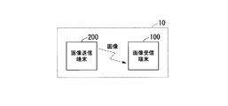
- FIG. 1 shows a configuration of an image communication system 10 according to the first embodiment of the present invention.
- the image communication system 10 includes an image reception terminal 100 and an image transmission terminal 200.
- the image receiving terminal 100 and the image transmitting terminal 200 perform wireless communication.
- the image communication system 10 is a wireless endoscope system.
- the image receiving terminal 100 is an endoscope processor, and the image transmitting terminal 200 is an endoscope scope.
- the image communication system 10 is not limited to a wireless endoscope system, and may be any system that can perform image communication wirelessly.
- the image receiving terminal 100 may be an STB (Set Top Box) that can be wirelessly connected to a digital camera or a portable terminal with a display.
- the image transmission terminal 200 may be a digital camera or a microscope.
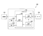
- FIG. 2 shows the configuration of the image receiving terminal 100.
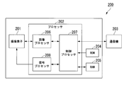
- FIG. 3 shows the configuration of the image transmission terminal 200.
- the image receiving terminal 100 includes at least a communication device 101 (first communication device) and a processor 102 (first processor).
- the communication device 101 receives a communication packet from the image transmission terminal 200 by using a wireless communication channel.
- One frame image is divided into a plurality of divided images, and the communication packet includes the divided images.
- One frame image corresponds to a plurality of communication packets.
- the processor 102 generates a display image of one frame from the divided images included in the plurality of communication packets received by the communication device 101.
- the processor 102 generates a vertical synchronization signal based on the clock.
- the processor 102 outputs the display image to the monitor 105 in synchronization with the vertical synchronization signal.
- the processor 102 measures a plurality of elapsed times by measuring the elapsed time every time the vertical synchronization signal is generated.
- the elapsed time is the time from when the vertical synchronization signal is generated to when the specific packet is received by the communication device 101.
- the specific packet is any one of a plurality of communication packets corresponding to an image of one frame.
- the processor 102 sets a determination reference time based on the plurality of measured elapsed times. Whether or not the processor 102 switches the communication channel used by the communication device 101 to another communication channel based on the set determination reference time and the elapsed time measured after the determination reference time is set Make a decision.
- the processor 102 controls switching of communication channels used by the communication device 101 based on the determination result.
- the specific packet is a communication packet that is received first among a plurality of communication packets corresponding to an image of one frame, that is, a head packet.
- the specific packet may be a communication packet other than the final packet among a plurality of communication packets corresponding to an image of one frame.
- the final packet is a communication packet received last among a plurality of communication packets corresponding to an image of one frame.
- the specific packet may be a final packet.
- the image receiving terminal 100 includes a communication device 101, a processor 102, a ROM 103, a RAM 104, and a monitor 105.
- a communication device 101 a communication device for communicating with the image receiving terminal 100.
- the communication device 101 is a wireless LAN (Local Area Network) module.
- the communication device 101 performs wireless communication with the image transmission terminal 200.
- the communication device 101 and the processor 102 are connected by a predetermined interface.
- the predetermined interface is USB (Universal Serial Bus), SDIO (Secure Digital Input / Output), or PCI Express.
- Wireless communication by the communication device 101 is performed on a communication channel set by the processor 102.
- the communication device 101 performs wireless communication using any one of a plurality of communication channels. Wireless communication by the communication device 101 is performed in accordance with protocols compliant with various interface standards.
- the communication device 101 receives a communication packet from the image transmission terminal 200 and outputs the received communication packet to the processor 102.
- the communication packet includes divided image data constituting the divided image.
- the processor 102 is composed of one or more processors.
- FIG. 2 shows an example in which the processor 102 includes a control processor 106, an image processor 107, and a signal processor 108.
- each processor includes at least one of a CPU (Central Processing Unit), an application specific integrated circuit (ASIC), an FPGA (Field-Programmable Gate Array), and the like.
- At least two of the control processor 106, the image processor 107, and the signal processor 108 may be configured as one processor.
- the control processor 106 performs various calculations and determinations according to the program.
- the program is stored in the ROM 103.
- the program in the ROM 103 is expanded in the RAM 104.
- the control processor 106 outputs the divided image data included in the plurality of communication packets received by the communication device 101 to the image processor 107.
- the control processor 106 measures the elapsed time and sets the determination reference time.
- the control processor 106 performs determination regarding communication channel switching and communication channel switching control.
- the control processor 106 controls image reception and image display of each frame based on the vertical synchronization signal.
- the control processor 106 determines to switch the communication channel used by the communication device 101 to another communication channel. In that case, the control processor 106 transmits the channel information to the image transmission terminal 200 through the communication device 101.
- the channel information indicates a communication channel used after the communication channel is switched. After the channel information is transmitted, the control processor 106 switches the communication channel used by the communication device 101 to the communication channel indicated by the channel information.
- the control processor 106 receives image data or information from the image transmission terminal 200 by the communication device 101. Specifically, the control processor 106 controls the communication device 101 so that image data or information is received from the image transmission terminal 200. That is, the control processor 106 causes the communication device 101 to receive the image data or information transmitted from the image transmission terminal 200. As a result, the communication device 101 receives image data or information from the image transmission terminal 200. The control processor 106 transmits information to the image transmission terminal 200 via the communication device 101. Specifically, the control processor 106 controls the communication device 101 so that information is transmitted to the image transmission terminal 200. That is, the control processor 106 causes the communication device 101 to transmit information for the image transmission terminal 200. As a result, the communication device 101 transmits information to the image transmission terminal 200.
- the image processor 107 generates a display image.
- the divided image data included in the communication packet received by the communication device 101 is compressed compressed image data.
- the image processor 107 generates display image data constituting a display image by expanding compressed image data corresponding to an image of one frame.
- the image processor 107 outputs the generated display image data to the monitor 105 in synchronization with the vertical synchronization signal.
- the signal processor 108 generates a vertical synchronization signal based on the clock.
- the vertical synchronization signal indicates a cycle in which the monitor 105 displays an image.
- the signal processor 108 outputs the generated vertical synchronization signal to the control processor 106 and the image processor 107.
- the signal processor 108 may be configured by a PLL (Phase Locked Loop) in the FPGA or a dedicated IC for video signal processing.
- the signal processor 108 may include an oscillating circuit such as a crystal oscillator module for generating a clock.
- control processor 106 the image processor 107, and the signal processor 108 can be realized as a software function by one processor reading and executing a program including instructions that define the operation of each processor. is there.
- This program may be provided by a “computer-readable recording medium” such as a flash memory.
- the above-described program may be transmitted to the image receiving terminal 100 from a computer having a storage device or the like in which the program is stored via a transmission medium or by a transmission wave in the transmission medium.
- a “transmission medium” for transmitting a program is a medium having a function of transmitting information, such as a network (communication network) such as the Internet or a communication line (communication line) such as a telephone line.
- the above-described program may realize a part of the functions described above.
- the above-described program may be a difference file (difference program) that can realize the above-described function in combination with a program already recorded in the computer.
- the ROM 103 is a non-volatile memory such as a Flash ROM.
- a program and various setting information are stored in the ROM 103.
- the program is used for controlling the image receiving terminal 100.
- the setting information includes communication setting parameters.
- the RAM 104 is a volatile memory.
- the RAM 104 is used as a buffer, a work area, and a temporary area.
- the buffer is used for temporary storage of image data.
- the work area is used for operations by the processor 102 and the like.
- the temporary area is used for temporary storage of various setting information.
- the monitor 105 displays the display image in units of frames according to the vertical synchronization signal.
- the monitor 105 may not be a part of the image receiving terminal 100. That is, the monitor 105 may be configured as a device independent of the image receiving terminal 100.
- the wireless communication environment has deteriorated. For this reason, an image reception delay is likely to occur. There is a high possibility that the wireless communication environment is improved by switching the communication channel. As a result of the communication channel switching, image reception delay is reduced.
- the image transmission terminal 200 includes at least an image sensor 201, a processor 202 (second processor), and a communication device 203 (second communication device).
- the image sensor 201 captures images at every imaging cycle, and outputs an image of one frame at each imaging cycle.
- the processor 202 generates a communication packet including divided images that constitute one frame image.
- the communication device 203 transmits a communication packet to the image receiving terminal 100 by using a wireless communication channel.
- the image transmission terminal 200 includes an image sensor 201, a processor 202, a communication device 203, a ROM 204, and a RAM 205.
- the image sensor 201 is an image sensor.
- the image sensor 201 is constituted by a CMOS sensor or a CCD.
- the image sensor 201 converts light imaged by the lens into an electrical signal, that is, an image signal.
- the imaging element 201 has an AD converter (analog-digital converter) that converts an analog imaging signal into a digital signal, that is, image data.
- the AD converter may be configured as a circuit subsequent to the image sensor 201.
- the image sensor 201 performs image capturing for each image capturing period in synchronization with the vertical synchronization signal, and acquires image data.
- the image sensor 201 outputs image data line by line.
- the processor 202 is composed of one or more processors.
- FIG. 3 shows an example in which the processor 202 includes an image processor 206, a control processor 207, and a signal processor 208.
- each processor includes at least one of a CPU, an application specific integrated circuit, and an FPGA.
- At least two of the image processor 206, the control processor 207, and the signal processor 208 may be configured as one processor.
- the image processor 206 processes the image output from the image sensor 201. For example, the image processor 206 generates compressed image data by compressing image data, that is, divided image data, in a predetermined line unit. Before the image data is compressed, the image processor 206 may perform image processing such as noise reduction. The compression rate of the image data may be variable. Alternatively, the image data may not be compressed.
- the control processor 207 performs various calculations and determinations according to the program.
- the program is stored in the ROM 204.
- the program in the ROM 204 is expanded in the RAM 205.
- the control processor 207 generates a communication packet including compressed divided image data, that is, compressed image data.
- One frame image corresponds to a plurality of communication packets.
- the control processor 207 outputs the generated communication packet to the communication device 203.
- the control processor 207 controls the image transmission of each frame based on the vertical synchronization signal.
- the control processor 207 controls switching of the communication channel used by the communication device 203 based on the result of switching of the communication channel by the control processor 106 of the image receiving terminal 100.
- the control processor 207 receives the channel information from the image receiving terminal 100 through the communication device 203.
- the control processor 207 switches the communication channel used by the communication device 203 to the communication channel indicated by the channel information.
- the control processor 207 transmits image data or information to the image receiving terminal 100 via the communication device 203. Specifically, the control processor 207 controls the communication device 203 so that image data or information is transmitted to the image receiving terminal 100. That is, the control processor 207 causes the communication device 203 to transmit image data or information for the image receiving terminal 100. As a result, the communication device 203 transmits image data or information to the image receiving terminal 100.
- the control processor 207 receives information from the image receiving terminal 100 via the communication device 203. Specifically, the control processor 207 controls the communication device 203 so that information is received from the image receiving terminal 100. That is, the control processor 207 causes the communication device 203 to receive information transmitted from the image receiving terminal 100. As a result, the communication device 203 receives information from the image receiving terminal 100.
- the signal processor 208 generates a vertical synchronization signal based on the clock.
- the signal processor 208 outputs the generated vertical synchronization signal to the image sensor 201 and the control processor 207.
- the signal processor 208 may be configured by a PLL in the FPGA or a dedicated IC for video signal processing.
- the signal processor 208 may include an oscillation circuit such as a crystal oscillator module for generating a clock.
- the functions of the image processor 206, the control processor 207, and the signal processor 208 can be realized as a software function by one processor reading and executing a program including instructions that define the operation of each processor. is there.
- the implementation form of this program is the same as the implementation form of the program that implements the functions of the processor 102.
- the communication device 203 is a wireless LAN module.
- the communication device 203 performs wireless communication with the image receiving terminal 100.
- the communication device 203 and the processor 202 are connected by a predetermined interface.
- Wireless communication by the communication device 203 is performed on a communication channel set by the processor 202.
- the communication device 203 performs wireless communication using any one of a plurality of communication channels. Wireless communication by the communication device 203 is performed in accordance with protocols compliant with various interface standards.
- ROM 204 is a non-volatile memory such as a Flash ROM.
- a program and various setting information are stored in the ROM 204.
- the program is used for controlling the image transmission terminal 200.
- the setting information includes communication setting parameters.
- the RAM 205 is a volatile memory.
- the RAM 205 is used as a buffer, a work area, and a temporary area.
- the buffer is used for temporary storage of image data.
- the work area is used for operations by the processor 202 and the like.
- the temporary area is used for temporary storage of various setting information.
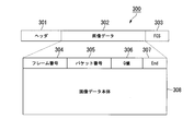
- FIG. 4 shows an example of the structure of a communication packet.
- the communication packet 300 includes a header 301, image data 302, and FCS (Frame Check Sequence) 303.
- FCS Frae Check Sequence
- the header 301 includes address information of the image receiving terminal 100 and the image transmitting terminal 200.
- the FCS 303 includes a CRC (Cyclic Redundancy Check) value for error checking.
- the image data 302 includes a frame number 304, a packet number 305, a Q value 306, an End 307, and an image data body 308.
- the frame number 304 is a number assigned to each frame image.
- the packet number 305 is a number that is incremented for each communication packet in order from 1 in an image of one frame.
- the packet number 305 starts from 1 for each frame.
- the Q value 306 is a value indicating the compression level of the image. With the Q value 306, the maximum data size of the compressed image data can be estimated. Instead of the Q value 306, data size information of a compressed one-frame image may be stored.
- End 307 indicates whether the communication packet is the last packet of an image of one frame. “1” is stored in the End 307 in the final packet of the image of one frame, and “0” is stored in the End 307 in the communication packet other than the final packet.
- the image data body 308 is compressed divided image data, that is, compressed image data.
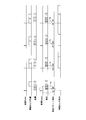
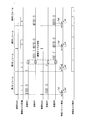
- FIG. 5 shows a schematic operation of the image receiving terminal 100 and the image transmitting terminal 200.
- the horizontal direction in FIG. 5 indicates time.
- “Transmission Vsync” indicates a vertical synchronization signal in the image transmission terminal 200.
- “Imaging and compression” indicates the timing of imaging and compression of an image in the image transmission terminal 200.
- “Transmission” indicates the timing at which the communication packet is transmitted by the image transmission terminal 200.
- “Reception Vsync” indicates a vertical synchronization signal in the image receiving terminal 100.
- “Reception” indicates the timing at which the communication packet is received by the image receiving terminal 100.
- “Specific packet detection” indicates a timing at which a specific packet is detected. In FIG. 5, the specific packet is the head packet.
- Extension and display indicates the timing of image extension and display in the image receiving terminal 100.
- the vertical sync signal indicates the start timing of the frame.
- the vertical synchronization signal in the image transmission terminal 200 is synchronized with the vertical synchronization signal in the image reception terminal 100 as a reference.
- There are various methods for synchronizing the vertical synchronization signals on the transmission side and the reception side For example, a method disclosed in Japanese Unexamined Patent Publication No. 2011-109226 may be used.
- the image sensor 201 captures an image of the subject in synchronization with the vertical synchronization signal generated by the signal processor 208 and outputs image data.
- the image processor 206 performs compression processing on the image data output from the image sensor 201.
- the control processor 207 generates a communication packet including the compressed divided image data, and outputs the generated communication packet to the communication device 203.
- the communication device 203 sequentially transmits communication packets to the image receiving terminal 100 according to the communication protocol.
- the communication device 101 sequentially receives communication packets.
- the control processor 106 detects that the head packet, which is a specific packet, has been received by the communication device 101, the control processor 106 generates a specific packet detection flag. For example, after the vertical synchronization signal is generated, the control processor 106 determines that the communication packet received first is the head packet. Alternatively, when the packet number is added to the head portion of the image data of the communication packet, the control processor 106 recognizes the communication packet having the packet number “1” as the head packet. The packet number is added to the communication packet by the control processor 207.
- the control processor 106 measures the elapsed time Ta from the time indicated by the vertical synchronization signal generated before the specific packet detection flag is generated to the time when the specific packet detection flag is generated. Immediately after image transmission is started, the determination reference time is set to an initial value. The control processor 106 updates the determination reference time based on the elapsed time Ta measured in a plurality of frames. FIG. 5 shows an operation after the determination reference time is updated.
- the control processor 106 outputs the divided image data included in the communication packet to the image processor 107.
- the image processor 107 generates display image data by expanding the divided image data corresponding to an image of one frame.
- the image processor 107 outputs the generated display image data to the monitor 105 in synchronization with the vertical synchronization signal.
- the monitor 105 displays a display image based on the display image data.
- the initial value of the determination reference time is set in consideration of the time assumed when the number of retransmissions of a specific packet is maximized and the known transmission delay time.
- the time that is assumed when the number of retransmissions of a specific packet is maximized is based on the transmission time per packet and the retransmission interval.
- the retransmission interval includes a DIFS defined in IEEE 802.11 and a backoff time.
- the transmission time per packet is calculated using an intermediate value among the values of the physical rate at which communication is possible.
- the back-off time is determined randomly within a range of a predetermined time (contention window set value CW).
- the initial value of the determination reference time may be set by the back-off time when an intermediate value of the set value CW is used.
- the known transmission delay time is a fixed value defined by the processing time of the entire system. The fixed value is stored in the ROM 103.
- the initial value of the determination reference time is set based on the time corresponding to the applied communication standard, the time corresponding to the communication speed table that can be applied on the transmission side and the reception side, and the fixed value stored in the ROM 103.
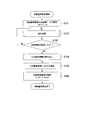
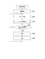
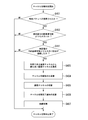
- FIG. 6 shows the overall procedure for setting the criterion.
- the control processor 106 sets the determination reference time T_ref to the initial value T_ini of the determination reference time (step S101).
- the initial value T_ini of the determination reference time is a fixed value stored in the ROM 103.
- the initial value T_ini of the determination reference time is a value calculated from the elapsed time Ta measured in the past communication. Also good.
- the initial value T_ini of the determination reference time is stored in the RAM 104.
- the image receiving terminal 100 may have an EEPROM (Electronically Erasable and Programmable Read Only Memory), and the elapsed time Ta measured during past communication may be stored in the EEPROM.
- EEPROM Electrically Erasable and Programmable Read Only Memory
- control processor 106 After the initial value T_ini of the determination reference time is set, the control processor 106 performs a measurement process.
- the control processor 106 measures the elapsed time Ta by the measurement process.
- the measurement result of the elapsed time Ta is stored in the RAM 104 as statistical information (step S102).
- control processor 106 determines whether or not a predetermined time has elapsed since the initial value T_ini of the determination reference time has been set (step S103). If the control processor 106 determines in step S103 that the predetermined time has not elapsed, the measurement process in step S102 is performed. That is, the measurement process is repeatedly performed within a predetermined time.
- step S103 when the control processor 106 determines that the predetermined time has elapsed, the control processor 106 reads the statistical information of the elapsed time Ta from the RAM 104 (step S104).
- control processor 106 extracts the longest time T_worst that is the maximum value of the elapsed time Ta from the statistical information (step S105).
- the control processor 106 updates the judgment reference time T_ref with the longest time T_worst. That is, the longest time T_worst is set as the determination reference time T_ref.
- the updated determination reference time T_ref is stored in the RAM 104 (step S106). When the determination reference time T_ref is updated, the determination reference setting is completed.
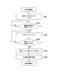
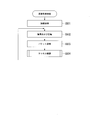
- FIG. 7 shows the procedure of the measurement process (step S102).
- the control processor 106 clears the measurement counter (step S201). At this time, the value T_cnt of the measurement counter becomes zero. The value T_cnt of the measurement counter indicates the elapsed time Ta.
- control processor 106 waits until a vertical synchronization signal is generated by the signal processor 108 (step S202).
- control processor 106 increments the value T_cnt of the measurement counter (step S203).
- control processor 106 monitors the communication device 101 and determines whether or not a specific packet has been received (step S204). If the control processor 106 determines in step S204 that the specific packet has not been received, the processing in step S204 continues.
- Step S204 when the control processor 106 determines that the specific packet is received, the control processor 106 generates a specific packet detection flag (Step S205).
- the control processor 106 updates the statistical information of the elapsed time Ta by adding the value T_cnt of the measurement counter to the statistical information of the elapsed time Ta (step S206).
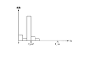
- the statistical information of the elapsed time Ta is a histogram of the elapsed time Ta.
- the initial value T_ini is used as the determination reference time and the statistical information of the elapsed time Ta is accumulated in the RAM 104 until a predetermined time elapses.
- the predetermined time is a time of two frames or more. Therefore, the control processor 106 measures the elapsed time every time the vertical synchronization signal is generated in a period of two frames or more. For example, the predetermined time is 20 seconds. When one second is composed of 60 frames, the predetermined time is a time corresponding to 1200 frames. That is, the elapsed time Ta is measured 1200 times. After the predetermined time has elapsed, the control processor 106 reads a histogram of the elapsed time Ta from the RAM 104.
- the control processor 106 updates the determination reference time T_ref based on the measured value of the elapsed time Ta in the histogram.
- the determination reference time is set to the longest time T_worst which is the maximum value of the elapsed time Ta. That is, the control processor 106 sets the longest elapsed time Ta among the plurality of measured elapsed times Ta as the determination reference time T_ref.
- the judgment reference time may be set to the mode value of the elapsed time Ta. That is, the control processor 106 may set the elapsed time Ta having the highest appearance frequency among the plurality of measured elapsed times Ta as the determination reference time.
- the updated determination reference time T_ref is the maximum value of the elapsed time Ta.
- the updated determination reference time T_ref is the mode value of the measured elapsed time Ta.
- the updated determination reference time T_ref is smaller than the initial value T_ini of the determination reference time.
- the updated determination reference time T_ref may be greater than the initial value T_ini of the determination reference time.
- a stricter or looser judgment reference time may be set based on the maximum value or the mode value that is an actual measurement value of the elapsed time Ta.
- the control processor 106 may set the determination reference time T_ref in consideration of a predetermined value based on the maximum value or the mode value.
- the predetermined value may be a value considering the variation of the histogram, that is, the standard deviation ⁇ .
- the control processor 106 sets a value that is 3 ⁇ smaller than the maximum value or the mode value as the determination reference time T_ref in order to secure a margin of 3 ⁇ . As a result, a stricter judgment reference time T_ref is set.
- the control processor 106 sets the value that is 3 ⁇ larger than the maximum value or the mode value as the determination reference time T_ref. .
- a looser judgment reference time T_ref is set.
- control processor 106 sets the time based on the longest elapsed time Ta among the plurality of measured elapsed times Ta as the determination reference time T_ref.
- control processor 106 sets a time based on the elapsed time Ta having the highest appearance frequency among the plurality of measured elapsed times Ta as the determination reference time T_ref.
- the method for setting the determination reference time T_ref may be a method other than the above.
- the control processor 106 may set the determination reference time T_ref based on the statistical information of the elapsed time Ta a plurality of times. That is, the control processor 106 may constantly update the statistical information of the elapsed time Ta and periodically update the determination reference time. For example, the control processor 106 updates the determination reference time once every 60 seconds. By regularly updating the judgment reference time, a more suitable judgment reference time is set according to changes in the wireless communication environment. For this reason, the reception delay of the image accompanying the deterioration of the wireless communication environment can be reduced in real time.
- the time range in which the frequency is calculated may be set narrow. That is, the resolution in the time direction in the histogram of the elapsed time Ta may be set high. Thereby, a minute change in the elapsed time Ta can be detected.
- the operation of the image receiving terminal 100 in the reception process will be described with reference to FIG. 10 and FIG.
- the image receiving terminal 100 receives an image from the image transmitting terminal 200 by the receiving process, and displays the received image.
- the processes shown in FIGS. 10 and 11 are performed in parallel with the processes shown in FIGS.
- FIG. 10 shows the overall procedure of the reception process.
- the control processor 106 performs connection processing (step S301).
- the control processor 106 connects to the image transmission terminal 200 wirelessly through the communication device 101.
- the control processor 106 sets a communication channel in the communication device 101.
- a communication link between the image receiving terminal 100 and the image transmitting terminal 200 is established, and data communication is possible. Since the connection process is a general process, a detailed description of the connection process is omitted.
- control processor 106 receives a communication packet from the image transmission terminal 200 by the communication device 101 (step S302).
- the divided image data included in the received communication packet is stored in the RAM 104.
- control processor 106 After the communication packet is received, the control processor 106 performs channel switching determination (step S303). The control processor 106 determines whether to switch the communication channel used by the communication device 101 to another communication channel based on the channel switching determination. When the wireless communication environment is deteriorated, the control processor 106 switches the communication channel.
- the control processor 106 determines whether or not an image of one frame has been received (step S304). For example, if End 307 added to the communication packet received in step S302 is “1” immediately before the determination in step S304, the control processor 106 determines that an image of one frame has been received. When End 307 is “0”, the control processor 106 determines that one frame image has not been received.
- step S304 when the control processor 106 determines that an image of one frame has not been received, the process in step S302 is performed. If the control processor 106 determines that an image of one frame has been received in step S304, the control processor 106 reads out the divided image data corresponding to the image of one frame from the RAM 104, and outputs the read divided image data to the image. Output to the processor 107.
- the image processor 107 generates display image data by expanding the divided image data corresponding to the image of one frame (step S305). As described above, the image data may not be compressed. Therefore, in step S305, the image processor 107 may generate display image data from the divided image data corresponding to the image of one frame without expanding the divided image data.
- the image processor 107 After the display image data is generated, the image processor 107 outputs the generated display image data to the monitor 105 (step S306). As a result, the monitor 105 displays a display image based on the display image data. After the display image data is output, the process in step S302 is performed.
- the control processor 106 transmits an ACK to the image transmission terminal 200 by the communication device 101.
- ACK indicates normal reception of the communication packet. Since the process regarding ACK is a general process, the process is abbreviate
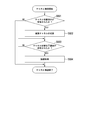
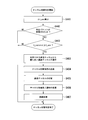
- FIG. 11 shows the procedure for channel switching determination (step S303).
- the control processor 106 determines whether a specific packet has been received. That is, the control processor 106 determines whether or not the communication packet received in step S302 immediately before the channel switching determination is a specific packet (step S401). In step S401, when the control processor 106 determines that the specific packet has not been received, the channel switching determination ends.
- step S401 when the control processor 106 determines that the specific packet is received, the control processor 106 determines whether or not the measured value of the elapsed time is larger than the determination reference time (step S402). In parallel with the channel switching determination, processing similar to the measurement processing shown in FIG. 7 is performed. Thereby, the elapsed time is measured. In step S402, this elapsed time measurement is used.
- the determination reference time used in step S402 is the initial value T_ini of the determination reference time or the updated determination reference time T_ref.
- step S402 when the measured value of the elapsed time is equal to or less than the determination reference time, the control processor 106 determines not to switch the communication channel used by the communication device 101. In this case, the channel switching determination ends.
- step S402 when the measured value of the elapsed time is larger than the determination reference time, the control processor 106 determines to switch the communication channel used by the communication device 101. In this case, the control processor 106 selects the best communication channel from available communication channels other than the communication channel used by the communication device 101 (step S403).
- the communication channel selected in step S403 is different from the communication channel used by the communication device 101.
- the communication channel selected in step S403 may be a communication channel with better communication quality than the communication channel used by the communication device 101.
- the control processor 106 estimates the quality of a plurality of communication channels that can be used by the communication device 101 in parallel with the control shown in FIGS.
- a well-known method may be used as a method for estimating a communication environment state, that is, channel quality estimation. For example, while the communication channel is switched, packets are periodically transmitted from the receiving side to the transmitting side, and the error rate, RSSI (Received Signal Strength Indicator), and SN ratio (signal-to-noise ratio) A method in which any one of the above is measured can be applied.
- the communication device 101 and the communication device 203 may be configured to be able to simultaneously use a communication channel for image communication and a communication channel for channel quality estimation.
- the image receiving terminal 100 and the image transmitting terminal 200 may have a communication device for channel quality estimation in addition to the communication device 101 and the communication device 203. Since the method for switching the communication channel to a good communication channel may be a general method, a detailed description of the method is omitted.
- the control processor 106 transmits a channel switching instruction to the image transmission terminal 200 through the communication device 101 (step S404).
- the channel switching instruction includes channel information.
- the channel information indicates a communication channel used after the communication channel is switched. That is, the channel information indicates the communication channel selected in step S403.
- the control processor 106 sets the communication channel selected in step S403 in the communication device 101 (step S405). Thereby, the control processor 106 switches the communication channel set in the communication device 101 to the communication channel selected in step S403. For example, when the communication channel is switched, an initial value is set as the determination reference time.
- control processor 106 transmits a channel switching completion notification to the image transmission terminal 200 by the communication device 101 (step S406).
- the communication channel set in the communication device 101 in step S405 is used.
- the channel switching completion notification indicates completion of communication channel switching.
- the control processor 106 After the channel switching completion notification is transmitted, the control processor 106 performs connection processing (step S407). In the connection process, the control processor 106 connects to the image transmission terminal 200 wirelessly through the communication device 101. At this time, the communication channel set in the communication device 101 in step S405 is used. Through the connection process, a communication link between the image receiving terminal 100 and the image transmitting terminal 200 is established, and data communication is possible. Since the connection process is a general process, a detailed description of the connection process is omitted. When the connection process is performed, the channel switching determination ends.
- the operation of the image transmission terminal 200 in the transmission process will be described with reference to FIGS.
- the image transmission terminal 200 transmits an image to the image reception terminal 100 by transmission processing.
- FIG. 12 shows the entire procedure of the transmission process.
- the control processor 207 performs connection processing (step S501).
- the control processor 207 connects to the image receiving terminal 100 wirelessly through the communication device 203.
- the control processor 207 sets a communication channel in the communication device 203.
- the connection process in step S501 corresponds to the connection process in step S301.
- the image sensor 201 acquires image data by performing image capturing, and the image processor 206 performs compression processing on the image data (step S502).
- control processor 207 transmits a communication packet to the image receiving terminal 100 through the communication device 203 (step S503).
- the communication packet includes the divided image data compressed in step S502.
- control processor 207 After the communication packet is transmitted, the control processor 207 performs channel confirmation (step S504).
- the control processor 207 confirms whether or not switching of the communication channel is instructed from the image receiving terminal 100 by channel confirmation. When switching of the communication channel is instructed from the image receiving terminal 100, the control processor 207 switches the communication channel. After the channel confirmation is performed, the process in step S502 is performed.
- the control processor 207 receives the ACK from the image receiving terminal 100 by the communication device 203. If an ACK is received within a predetermined time, the next communication packet is transmitted. If an ACK is not received within a predetermined time, the same communication packet is retransmitted.
- the ACK processing in the MAC layer of the wireless LAN defined by IEEE 802.11 may be performed by the communication device 101 and the communication device 203. Since the process regarding ACK is a general process, the process is abbreviate
- FIG. 13 shows the procedure of channel confirmation (step S504).
- the communication device 203 receives the channel switching instruction.
- the control processor 207 monitors the communication device 203 and determines whether or not a channel switching instruction has been received (step S601). If the control processor 207 determines in step S601 that a channel switching instruction has not been received, channel confirmation ends.
- step S601 when the control processor 207 determines that the channel switching instruction is received, the control processor 207 sets the communication channel indicated by the channel information included in the channel switching instruction in the communication device 203 (step S602). As a result, the control processor 207 switches the communication channel set in the communication device 203 to the communication channel indicated by the channel information.
- the communication device 203 receives the channel switching completion notification. At this time, the communication channel set in the communication device 203 in step S602 is used. After the communication channel is switched, the control processor 207 monitors the communication device 203 and determines whether a channel switching completion notification has been received (step S603). If the control processor 207 determines in step S603 that a channel switching completion notification has not been received, the determination in step S603 continues.
- step S603 when the control processor 207 determines that a channel switching completion notification has been received, the control processor 207 performs connection processing (step S604).
- the control processor 207 connects to the image receiving terminal 100 wirelessly through the communication device 203.
- the communication channel set in the communication device 203 in step S602 is used.
- the connection process in step S604 corresponds to the connection process in step S407.
- FIGS. 14 and 15 show schematic operations of the image receiving terminal 100 and the image transmitting terminal 200 when the communication channel is switched.
- the horizontal direction in FIGS. 14 and 15 indicates time.
- the items shown in FIGS. 14 and 15 are the same as the items shown in FIG. 14 and 15, “transmission” and “reception” are shown for each of the communication channel CH1 and the communication channel CH2. 14 and 15 show the operation after the determination reference time is updated.
- the specific packet is the top packet.
- the elapsed time Ta1 to the elapsed time Ta4 measured for each of the four consecutive frames are shown.
- the communication channel CH1 is used.
- the specific packet is transmitted and received on the communication channel CH1.
- the elapsed time Ta1 is smaller than the determination reference time T_ref. For this reason, the control processor 106 determines not to switch the communication channel used by the communication device 101.
- the control processor 106 determines to switch the communication channel used by the communication device 101. In the second frame, the control processor 106 switches the communication channel used by the communication device 101 from the communication channel CH1 to the communication channel CH2. In the second frame, the communication packet after the specific packet is transmitted and received on the communication channel CH2. In the second frame, one frame of image data necessary for decompression and display is received in a time within one frame.
- the control processor 106 determines not to switch the communication channel used by the communication device 101.
- the specific packet is the final packet.
- the operation shown in FIG. 15 is the same as the operation shown in FIG. 14 except that the specific packet is the final packet.
- the communication channel CH1 is used.
- the elapsed time Ta1 is smaller than the judgment reference time T_ref
- the communication channel is not switched.
- the elapsed time Ta2 is longer than the determination reference time T_ref.
- the control processor 106 switches the communication channel used by the communication device 101 from the communication channel CH1 to the communication channel CH2.
- one frame of image data necessary for decompression and display is received in a time within one frame.
- the third and fourth frames since the elapsed time Ta3 and the elapsed time Ta4 are smaller than the judgment reference time T_ref, the communication channel is not switched.
- the specific packet may be a communication packet other than the first packet and the last packet.
- a description of the operation when the specific packet is a communication packet other than the first packet and the last packet is omitted.
- the reason why the elapsed time fluctuates is that a communication packet transmitted from the transmission side is not received at the reception side, and an ACK is not returned from the reception side to the transmission side, so that retransmission processing occurs at the transmission side.
- a possible cause of retransmission is the deterioration of the wireless communication environment.
- the deterioration of the wireless communication environment includes at least one of interference by other wireless devices, occurrence of fading, and change of the multipath environment. Therefore, there is a high possibility that the wireless communication environment is improved by changing the wireless communication channel.
- the state in which the image receiving terminal 100 and the image transmitting terminal 200 have two or more communication devices and the link of the switching destination communication channel is established may always be maintained. For example, image transmission is performed on the main channel, and a communication link is maintained on the secondary channel.
- the image receiving terminal 100 and the image transmitting terminal 200 switch the communication channel so that the image is transmitted on the sub channel. Thereby, the time required for switching the communication channel can be shortened.
- channel quality estimation may be performed every predetermined time.
- the image receiving terminal according to each aspect of the present invention may not include at least one of the ROM 103, the RAM 104, and the monitor 105.
- the image transmission terminal according to each aspect of the present invention may not include at least one of the ROM 204 and the RAM 205.
- the image receiving method of each aspect of the present invention includes a first step, a second step, a third step, a fourth step, a fifth step, a sixth step, and a seventh step. Steps.
- the processor 202 receives a communication packet from the image transmission terminal 200 by the communication device 101 by using a wireless communication channel (step S302).
- the processor 202 generates a display image of one frame from the divided images included in the plurality of communication packets received by the communication device 101 (step S305).
- the processor 202 outputs the display image to the monitor 105 in synchronization with the vertical synchronization signal (step S306).
- the processor 202 measures a plurality of elapsed times by measuring the elapsed time every time the vertical synchronization signal is generated (step S102).
- the processor 202 sets a determination reference time based on the plurality of measured elapsed times (step S106).
- the processor 202 sets the communication channel used by the communication device 101 to another communication based on the set determination reference time and the elapsed time measured after the determination reference time is set. It is determined whether or not to switch to a channel (step S402).
- the processor 202 controls switching of the communication channel used by the communication device 101 based on the determination result (step S405).
- the image receiving method of each aspect of the present invention may not include steps other than the steps corresponding to the first to seventh steps.
- whether to switch the communication channel used by the communication device 101 to another communication channel based on the determination reference time and the elapsed time measured after the determination reference time is set Judgment is made. Based on the determination result, switching of the communication channel used by the communication device 101 is controlled. For this reason, it is possible to reduce image reception delay due to deterioration of the wireless communication environment.
- the specific packet is a communication packet other than the final packet
- the deterioration of the wireless communication environment can be detected at an earlier timing within one frame of the image. For this reason, it is possible to further reduce the image reception delay accompanying the deterioration of the wireless communication environment.
- the specific packet is a communication packet other than the final packet
- the specific packet is the last packet, the image reception delay can be reduced in a frame after the frame in which the communication channel is switched.
- the processor 102 when a plurality of elapsed times measured after the determination reference time is set continuously exceed the determination reference time, the processor 102 changes the communication channel used by the communication device 101 to another To switch to the other communication channel. That is, when all of the plurality of elapsed times continuously measured exceed the determination reference time, the processor 102 determines to switch the communication channel used by the communication device 101 to another communication channel.
- the plurality of elapsed times are measured in a plurality of consecutive frames.
- the control processor 106 can determine whether or not the deterioration of the wireless communication environment continues by determining whether or not a plurality of elapsed times continuously exceed the determination reference time.
- the number of elapsed times to be determined, that is, the number of frames is two or more.
- FIG. 16 shows the procedure for channel switching determination (step S303). The operation shown in FIG. 16 will be described while referring to differences from the operation shown in FIG.
- step S402 when the measured value of the elapsed time is larger than the determination reference time, the control processor 106 determines whether or not the state where the measured value of the elapsed time is larger than the determination reference time continues. That is, the control processor 106 determines whether or not a plurality of elapsed times measured in a plurality of consecutive frames including the current frame exceed the determination reference time (step S411).
- step S411 when at least one of the plurality of elapsed times is equal to or shorter than the determination reference time, the channel switching determination ends. In step S411, when all of the plurality of elapsed times are larger than the determination reference time, the control processor 106 determines to switch the communication channel used by the communication device 101. In this case, the process in step S403 is performed.
- the state of the wireless communication environment can be determined more accurately by determining the state of a plurality of elapsed times.
- an allowable frequency is set in advance for each of a plurality of elapsed times longer than the determination reference time.
- the allowable frequency decreases as the elapsed time becomes longer than the determination reference time. If the elapsed time measured after the determination reference time is set exceeds the determination reference time and the frequency of occurrence of the measured elapsed time is greater than the allowable frequency corresponding to the measured elapsed time, the processor 102 It is determined that the communication channel used by the communication device 101 is switched to another communication channel.
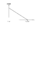
- FIG. 17 is an example of a graph showing the allowable frequency.
- the horizontal axis of the graph shown in FIG. 17 is the elapsed time Ta, and the vertical axis is the allowable frequency.
- the allowable frequency corresponding to the determination reference time T_ref is the largest.
- the allowable frequency corresponding to the limit value T_limit of the determination reference time is the smallest.
- the limit value T_limit of the determination reference time is larger than the determination reference time T_ref.
- the allowable frequency of the first elapsed time is smaller than the allowable frequency of the second elapsed time.
- the first elapsed time and the second elapsed time are included in a period from the determination reference time T_ref to the determination reference time limit value T_limit.
- the first elapsed time is longer than the second elapsed time.
- the allowable frequency is a linear function of the elapsed time Ta.
- the function indicating the relationship between the elapsed time Ta and the allowable frequency may be a function other than a linear function.
- the allowable frequency may be an exponential function of the elapsed time Ta.
- the control processor 106 calculates an allowable frequency based on the determination reference time T_ref.
- the allowable frequency information indicating the allowable frequency is stored in the RAM 104.
- the allowable frequency corresponding to the determination reference time T_ref may be a mode value in a histogram generated for updating the determination reference time.
- the limit value T_limit of the determination reference time may be the initial value T_ini of the determination reference time.
- the limit value T_limit of the determination reference time may be a time set based on a timing at which reception of one frame of image data should be completed. For example, the timing at which reception of one frame of image data is to be completed is immediately before the next vertical synchronization signal is generated at the image receiving terminal 100.
- a histogram similar to the histogram shown in FIGS. 8 and 9 is stored in the RAM 104.
- the control processor 106 updates the histogram.
- the control processor 106 extracts a frequency (occurrence frequency) corresponding to the measured elapsed time from the histogram. Further, the control processor 106 calculates an allowable frequency corresponding to the measured elapsed time based on the allowable frequency information.
- the control processor 106 compares the frequency extracted from the histogram with the allowable frequency.
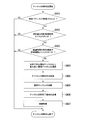
- FIG. 18 shows the procedure for channel switching determination (step S303). The operation shown in FIG. 18 will be described while referring to differences from the operation shown in FIG.
- step S402 when the measured value of the elapsed time is greater than the determination reference time, the control processor 106 determines whether or not the occurrence frequency of the elapsed time is greater than the allowable frequency (step S421).
- step S421 when the occurrence frequency of the elapsed time is equal to or less than the allowable frequency, the channel switching determination is finished.
- step S421 when the occurrence frequency of the elapsed time is greater than the allowable frequency, the control processor 106 determines to switch the communication channel used by the communication device 101. In this case, the process in step S403 is performed.
- an image reception delay can be reduced according to the degree of deterioration of the wireless communication environment.
- the specific packet is any one of communication packets other than the final packet among a plurality of communication packets corresponding to an image of one frame.
- the final packet is a communication packet received last among a plurality of communication packets corresponding to an image of one frame.
- the specific packet is a final packet.
- FIG. 19 and FIG. 19 and 20 show the procedure for channel switching determination (step S303).
- the operation shown in FIGS. 19 and 20 will be described while referring to differences from the operation shown in FIG. 19 and 20, the specific packet is a communication packet other than the final packet.
- the control processor 106 calculates an average value ⁇ t_ave of the reception intervals.
- the control processor 106 acquires the total data amount d_img and the data size pkt_size (step S431).
- the average value ⁇ t_ave of the reception interval is an average value of the interval at which the communication packet of the divided image data is received.
- the communication packet of the divided image data may be a specific packet.
- the average value ⁇ t_ave of the reception interval is calculated from the reception interval of the communication packet received before the specific packet is received in the frame in which the determination regarding the switching of the communication channel is performed.
- the total data amount d_img is a data amount of image data of one frame received in a frame in which a determination regarding switching of the communication channel is performed.
- the maximum value of the size of the compressed image data based on the Q value of the communication packet may be applied as the total data amount d_img.
- the data size pkt_size is the data amount of the divided image data included in one communication packet.
- the reception interval may be used instead of the average value ⁇ t_ave of the reception interval.
- the median value ⁇ t_med in the reception interval histogram may be used.
- a value in which the standard deviation ⁇ t_ ⁇ is considered based on the average value ⁇ t_ave or the median value ⁇ t_med of the reception interval may be used.
- step S432 the control processor 106 updates the received data amount d_rcv (step S432).
- the received data amount d_rcv is the total data amount of the divided image data included in the communication packet received in the frame in which the determination regarding the switching of the communication channel is performed.
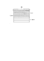
- FIG. 21 shows the total data amount d_img, the received data amount d_rcv, and the remaining data amount d_remain.
- one frame image IMG is composed of 8 lines.
- the image data of each line constitutes divided image data.
- the total data amount d_img is the total data amount of 8 lines.
- the received data amount d_rcv is the sum of the data amounts of the 5-line divided image data.
- the remaining data amount d_remain is the remaining data amount obtained by subtracting the received data amount d_rcv from the total data amount d_img. That is, the remaining data amount d_remain is the total amount of divided image data that has not yet been received by the communication device 101.
- the control processor 106 determines whether or not a specific packet has been received. That is, the control processor 106 determines whether or not the communication packet received in step S302 immediately before the channel switching determination is a specific packet (step S433). In step S433, if the control processor 106 determines that the communication packet is not a specific packet, the channel switching determination ends.
- step S433 If the control processor 106 determines in step S433 that the communication packet is a specific packet, the control processor 106 calculates the remaining data amount d_remain and acquires the communication rate Rate (step S434).
- the remaining data amount d_remain is calculated by equation (1).
- d_remain d_img ⁇ d_rcv (1)
- the communication rate Rate is a communication rate when a specific packet is received.
- the wireless LAN PHY rate may be used as the communication rate.
- the actual reception throughput may be used as the communication rate.
- the average value calculation range is one frame. That is, the average value of the reception throughput of a plurality of communication packets corresponding to one frame image is calculated.
- the calculation range of the average value may be a plurality of frames.
- the average value calculation range may be a frame included in 10 seconds. That is, when one second is composed of 60 frames, the average value calculation range may be 600 frames.
- step S435 the control processor 106 calculates an allowable time t_allow (step S435).
- the allowable time t_allow is an allowable value of the time required for receiving each communication packet received after the specific packet.
- step S435 the control processor 106 divides the remaining data amount d_remain by the data size pkt_size to calculate the number of communication packets necessary for receiving the divided image data that has not yet been received.
- step S435 the control processor 106 calculates the reception allowable time of one communication packet by dividing the remaining time t_remain by the number of communication packets. The remaining time t_remain is the remaining time in one frame.
- step S435 the control processor 106 calculates the allowable time t_allow by subtracting the average value ⁇ t_ave of the reception interval from the allowable reception time. That is, the control processor 106 calculates the allowable time t_allow according to the equation (2).
- t_allow t_remain / (d_remain / pkt_size) ⁇ t_ave (2)
- FIG. 22 shows a schematic operation of the image receiving terminal 100.
- the horizontal direction in FIG. 22 indicates time.
- “reception Vsync”, “reception”, “specific packet detection”, and “decompression and display” are shown. These items are the same as the items shown in FIG.
- the elapsed time Ta, the remaining time t_remain, and the allowable time t_allow are shown.
- the specific packet is a communication packet received fourth among a plurality of communication packets corresponding to an image of one frame.
- the remaining time t_remain is the time from when the specific packet is received to when the decompression process is started. In one frame, three communication packets are received after the specific packet.
- the allowable time t_allow is close to the time obtained by dividing the remaining time t_remain into three equal parts.
- the allowable time t_allow is based on a value obtained by equally dividing the remaining time t_remain by the number of communication packets.
- the allowable time t_allow is not limited to this.
- the remaining time t_remain may be allocated so that a longer time can be secured for a communication packet closer to the final packet.
- Equation (3) is a preset number of retransmissions.
- Expression (3) indicates that the estimated time required for reception when the communication packet including the divided image data is transmitted at the communication rate Rate is longer than the allowable time t_allow.
- the data size of the divided image data is pkt_size.
- step S436 when the expression (3) is not satisfied, the reception of the determination target packet is completed before the display image is displayed on the monitor 105. In this case, the control processor 106 determines not to switch the communication channel used by the communication device 101, and the channel switching determination ends.
- step S436 when Expression (3) is satisfied, it is estimated that the reception of the determination target packet is not completed before the display image is displayed on the monitor 105. In this case, the process in step S403 is performed.
- FIGS. 19 and 20 are the same as the operations shown in FIG.
- Multiple specific packets may exist in one frame. That is, when each of a plurality of specific packets is received in one frame, the control processor 106 determines whether reception of the determination target packet is completed before display of the display image by the monitor 105. Also good.
- the specific packet is any one of communication packets other than the final packet among a plurality of communication packets corresponding to one frame image.
- the processor 102 calculates the total amount (d_remain) of the divided images that have not yet been received by the communication device 101 among the divided images constituting one frame image (Ste S434).
- the processor 102 determines whether or not the reception of the determination target packet is completed before the display of the display image by the monitor 105, based on the total data amount (d_remain) of the divided images and the communication rate (Rate) of the communication device 101. Based on the determination (step S436).
- the determination target packet is a communication packet received by the communication device 101 after the specific packet is received. If the reception of the determination target packet is not completed before the display of the display image by the monitor 105, the processor 102 determines to switch the communication channel used by the communication device 101 to another communication channel (step S436). .
- the steps (S431, S432, S434, and S435) for obtaining information for the processor 102 to make a determination are an example.
- the processor 102 may acquire information by a method other than the above method.
- FIG. 23 shows a procedure for channel switching determination (step S303). The operation shown in FIG. 23 will be described while referring to differences from the operation shown in FIG. In the operation shown in FIG. 23, the specific packet is the final packet.
- the control processor 106 calculates the average value ⁇ t_ave of the reception intervals (step S441).
- the calculation method of the average value ⁇ t_ave of the reception intervals is the same as the method in step S431 shown in FIG. As described above, instead of the average value ⁇ t_ave of the reception intervals, other statistical values regarding the reception intervals may be used.
- the control processor 106 determines whether or not a specific packet has been received. That is, the control processor 106 determines whether or not the communication packet received in step S302 immediately before the channel switching determination is a specific packet (step S442). If the control processor 106 determines in step S442 that the communication packet is not a specific packet, the channel switching determination ends.
- step S442 when the control processor 106 determines that the communication packet is a specific packet, the control processor 106 determines whether or not the remaining time t_remain is smaller than the average value ⁇ t_ave of the reception intervals (step S443). In step S443, when the control processor 106 determines that the remaining time t_remain is smaller than the average value ⁇ t_ave of the reception intervals, the process in step S403 is performed. In step S443, when the control processor 106 determines that the remaining time t_remain is equal to or greater than the average value ⁇ t_ave of the reception intervals, the channel switching determination ends.
- the specific packet is the final packet.
- the processor 102 measures the reception interval ( ⁇ t_ave) of the communication packet received before the specific packet is received (step S441).
- the processor 102 determines whether or not the remaining time (t_remain) in one frame when the specific packet is received is shorter than the communication packet reception interval (step S443). If the remaining time in one frame is shorter than the communication packet reception interval, the processor 102 determines to switch the communication channel used by the communication device 101 to another communication channel (step S443).
- a plurality of communication packets including the final packet among a plurality of communication packets corresponding to one frame image are specific packets. If a specific packet other than the final packet is received, a determination is made in step S436. If the last packet has been received, a determination is made in step S443.
- the specific packet can be arbitrarily set in one frame.
- the wireless communication environment is determined. For this reason, it is possible to detect deterioration of the wireless communication environment at an arbitrary timing of one frame.
- the elapsed time varies depending on the position of the specific packet in the plurality of communication packets. When two or more specific packets are set in one frame, it is necessary to obtain elapsed time statistical information for each specific packet. For this reason, the processing load is high.
- the information acquired for the determination of the wireless communication environment in the fourth embodiment can be commonly used in the determination for each specific packet regardless of the position of the specific packet. For this reason, an increase in processing load is suppressed. Therefore, when two or more specific packets are set in one frame, an increase in processing load is suppressed, and real-time performance in image transmission can be further ensured.
- each embodiment of the present invention it is possible to reduce image reception delay due to deterioration of the wireless communication environment.
Landscapes
- Engineering & Computer Science (AREA)
- Signal Processing (AREA)
- Multimedia (AREA)
- Computer Networks & Wireless Communication (AREA)
- Two-Way Televisions, Distribution Of Moving Picture Or The Like (AREA)
- Mobile Radio Communication Systems (AREA)
Abstract
La présente invention concerne un terminal de réception d'images qui comprend un dispositif de communication et un processeur ou une pluralité de processeurs. Le processeur mesure une pluralité de temps écoulés. Le temps écoulé est un temps entre le moment où un signal de synchronisation verticale est généré et un moment où un paquet spécifique est reçu par le dispositif de communication. Le processeur définit un temps de référence de détermination sur la base de la pluralité des temps écoulés mesurés. Le processeur détermine, sur la base du temps de référence de détermination défini et du temps écoulé mesuré après que le temps de référence de détermination a été défini, s'il faut changer le canal de communication, que le dispositif de communication utilise, pour un autre canal de communication. Le processeur commande, sur la base d'un résultat de la détermination, la commutation du canal de communication que le dispositif de communication utilise.
Priority Applications (3)
| Application Number | Priority Date | Filing Date | Title |
|---|---|---|---|
| PCT/JP2016/055018 WO2017145224A1 (fr) | 2016-02-22 | 2016-02-22 | Terminal de réception d'images, système de communication d'images, procédé de réception d'images et programme |
| JP2018501414A JP6646132B2 (ja) | 2016-02-22 | 2016-02-22 | 画像受信端末、画像通信システム、画像受信方法、およびプログラム |
| US16/106,418 US10587783B2 (en) | 2016-02-22 | 2018-08-21 | Image reception terminal, image communication system, image reception method, and recording medium |
Applications Claiming Priority (1)
| Application Number | Priority Date | Filing Date | Title |
|---|---|---|---|
| PCT/JP2016/055018 WO2017145224A1 (fr) | 2016-02-22 | 2016-02-22 | Terminal de réception d'images, système de communication d'images, procédé de réception d'images et programme |
Related Child Applications (1)
| Application Number | Title | Priority Date | Filing Date |
|---|---|---|---|
| US16/106,418 Continuation US10587783B2 (en) | 2016-02-22 | 2018-08-21 | Image reception terminal, image communication system, image reception method, and recording medium |
Publications (1)
| Publication Number | Publication Date |
|---|---|
| WO2017145224A1 true WO2017145224A1 (fr) | 2017-08-31 |
Family
ID=59684888
Family Applications (1)
| Application Number | Title | Priority Date | Filing Date |
|---|---|---|---|
| PCT/JP2016/055018 Ceased WO2017145224A1 (fr) | 2016-02-22 | 2016-02-22 | Terminal de réception d'images, système de communication d'images, procédé de réception d'images et programme |
Country Status (3)
| Country | Link |
|---|---|
| US (1) | US10587783B2 (fr) |
| JP (1) | JP6646132B2 (fr) |
| WO (1) | WO2017145224A1 (fr) |
Families Citing this family (2)
| Publication number | Priority date | Publication date | Assignee | Title |
|---|---|---|---|---|
| JP6786407B2 (ja) * | 2017-01-23 | 2020-11-18 | 株式会社クボタ | 作業車無線管理システム |
| WO2018235258A1 (fr) * | 2017-06-23 | 2018-12-27 | オリンパス株式会社 | Système de transfert d'image, terminal d'imagerie, terminal d'affichage, procédé de réglage, procédé de prise en charge de réglage, programme de réglage et programme de prise en charge de réglage |
Citations (4)
| Publication number | Priority date | Publication date | Assignee | Title |
|---|---|---|---|---|
| JP2006217384A (ja) * | 2005-02-04 | 2006-08-17 | Mitsubishi Electric Corp | テレビカメラシステム、制御装置およびカメラ |
| JP2010284274A (ja) * | 2009-06-10 | 2010-12-24 | Olympus Corp | 無線内視鏡装置およびその受信装置ならびに受信方法 |
| JP2012509639A (ja) * | 2008-11-21 | 2012-04-19 | ストライカー・コーポレーション | 無線手術室通信システム |
| JP2012195794A (ja) * | 2011-03-17 | 2012-10-11 | Hitachi Consumer Electronics Co Ltd | 符号化信号受信装置 |
Family Cites Families (8)
| Publication number | Priority date | Publication date | Assignee | Title |
|---|---|---|---|---|
| US20020149617A1 (en) * | 2001-03-30 | 2002-10-17 | Becker David F. | Remote collaboration technology design and methodology |
| US7835343B1 (en) * | 2006-03-24 | 2010-11-16 | Rsi Video Technologies, Inc. | Calculating transmission anticipation time using dwell and blank time in spread spectrum communications for security systems |
| KR101252090B1 (ko) * | 2008-09-17 | 2013-04-12 | 엘지디스플레이 주식회사 | 액정표시장치 |
| JP5526638B2 (ja) | 2008-10-30 | 2014-06-18 | 株式会社Jvcケンウッド | ワイヤレス画像伝送装置およびワイヤレス画像伝送方法 |
| US8593570B2 (en) * | 2008-11-07 | 2013-11-26 | Looxcie, Inc. | Video recording camera headset |
| US8156238B2 (en) * | 2009-05-13 | 2012-04-10 | Stmicroelectronics, Inc. | Wireless multimedia transport method and apparatus |
| JP5508819B2 (ja) | 2009-11-13 | 2014-06-04 | オリンパス株式会社 | 受信装置 |
| US10091767B2 (en) * | 2015-08-20 | 2018-10-02 | Toshiba Memory Corporation | Communication apparatus and communication method |
-
2016
- 2016-02-22 WO PCT/JP2016/055018 patent/WO2017145224A1/fr not_active Ceased
- 2016-02-22 JP JP2018501414A patent/JP6646132B2/ja active Active
-
2018
- 2018-08-21 US US16/106,418 patent/US10587783B2/en active Active
Patent Citations (4)
| Publication number | Priority date | Publication date | Assignee | Title |
|---|---|---|---|---|
| JP2006217384A (ja) * | 2005-02-04 | 2006-08-17 | Mitsubishi Electric Corp | テレビカメラシステム、制御装置およびカメラ |
| JP2012509639A (ja) * | 2008-11-21 | 2012-04-19 | ストライカー・コーポレーション | 無線手術室通信システム |
| JP2010284274A (ja) * | 2009-06-10 | 2010-12-24 | Olympus Corp | 無線内視鏡装置およびその受信装置ならびに受信方法 |
| JP2012195794A (ja) * | 2011-03-17 | 2012-10-11 | Hitachi Consumer Electronics Co Ltd | 符号化信号受信装置 |
Also Published As
| Publication number | Publication date |
|---|---|
| US20180359393A1 (en) | 2018-12-13 |
| US10587783B2 (en) | 2020-03-10 |
| JPWO2017145224A1 (ja) | 2018-12-13 |
| JP6646132B2 (ja) | 2020-02-14 |
Similar Documents
| Publication | Publication Date | Title |
|---|---|---|
| US10524635B2 (en) | Endoscope, reception device, wireless endoscope system, image transmission method, image reception method, and non-transitory computer readable recording medium storing program | |
| JP6033032B2 (ja) | 撮像表示システム | |
| US9723193B2 (en) | Transmitting device, receiving system, communication system, transmission method, reception method, and program | |
| US10425827B2 (en) | Image communication system, image transmission apparatus, image transmission method, and recording medium | |
| US10542192B2 (en) | Image transfer system, image receiver, image transmitter, image transfer method, image reception method, image transmission method, and program | |
| US9198271B2 (en) | X-ray imaging apparatus, control device, radiation imaging apparatus, and method of controlling the same | |
| US10645726B2 (en) | Wireless communication terminal, wireless communication method, and recording medium | |
| US20120218430A1 (en) | Reception device | |
| JP2008219479A (ja) | 画像伝送システム、撮像装置、及び画像伝送方法 | |
| WO2018235258A1 (fr) | Système de transfert d'image, terminal d'imagerie, terminal d'affichage, procédé de réglage, procédé de prise en charge de réglage, programme de réglage et programme de prise en charge de réglage | |
| JP6646132B2 (ja) | 画像受信端末、画像通信システム、画像受信方法、およびプログラム | |
| US9055225B2 (en) | Display device and display system for performing a phase adjustment for a packet | |
| WO2014192689A1 (fr) | Système de communication sans fil et procédé de communication | |
| US10764616B2 (en) | Image transmission apparatus, image transmission method, and recording medium | |
| US20180070086A1 (en) | Compressed image data transmitting device, compressed image data transmitting and receiving system, compressed image data transmitting method, and non-transitory medium saving program | |
| US11184502B2 (en) | Communication system, reception terminal, communication method, and recording medium | |
| JP2012095200A (ja) | 画像処理装置、画像処理方法及びプログラム | |
| US11316627B2 (en) | Communication system, transmission device, communication method, and recording medium | |
| JP6141066B2 (ja) | 制御装置、撮像制御方法、コンピュータプログラム、及び撮像システム | |
| KR20120036663A (ko) | 차량용 고화질 영상 이미지 무선 전송 시스템의 무선 송신 제어 방법 | |
| JP7214396B2 (ja) | 通信装置、通信装置の制御方法およびプログラム | |
| CN119299833A (zh) | 一种rgb-d相机的多设备数据同步方法、装置、终端及介质 | |
| KR101609951B1 (ko) | 데이터 레이트 동기화 기능을 갖는 영상 송신 장치 및 영상 수신 장치 | |
| JP2017005588A (ja) | 表示制御装置及び表示制御方法 | |
| JP2004140691A (ja) | 動画データ通信システムおよび動画データ通信方法 |
Legal Events
| Date | Code | Title | Description |
|---|---|---|---|
| ENP | Entry into the national phase |
Ref document number: 2018501414 Country of ref document: JP Kind code of ref document: A |
|
| NENP | Non-entry into the national phase |
Ref country code: DE |
|
| 121 | Ep: the epo has been informed by wipo that ep was designated in this application |
Ref document number: 16891383 Country of ref document: EP Kind code of ref document: A1 |
|
| 122 | Ep: pct application non-entry in european phase |
Ref document number: 16891383 Country of ref document: EP Kind code of ref document: A1 |