WO2017145253A1 - Climatiseur - Google Patents
Climatiseur Download PDFInfo
- Publication number
- WO2017145253A1 WO2017145253A1 PCT/JP2016/055147 JP2016055147W WO2017145253A1 WO 2017145253 A1 WO2017145253 A1 WO 2017145253A1 JP 2016055147 W JP2016055147 W JP 2016055147W WO 2017145253 A1 WO2017145253 A1 WO 2017145253A1
- Authority
- WO
- WIPO (PCT)
- Prior art keywords
- outdoor unit
- heat exchanger
- air
- air conditioner
- sheet metal
- Prior art date
- Legal status (The legal status is an assumption and is not a legal conclusion. Google has not performed a legal analysis and makes no representation as to the accuracy of the status listed.)
- Ceased
Links
Images



Classifications
-
- F—MECHANICAL ENGINEERING; LIGHTING; HEATING; WEAPONS; BLASTING
- F24—HEATING; RANGES; VENTILATING
- F24F—AIR-CONDITIONING; AIR-HUMIDIFICATION; VENTILATION; USE OF AIR CURRENTS FOR SCREENING
- F24F1/00—Room units for air-conditioning, e.g. separate or self-contained units or units receiving primary air from a central station
- F24F1/06—Separate outdoor units, e.g. outdoor unit to be linked to a separate room comprising a compressor and a heat exchanger
- F24F1/14—Heat exchangers specially adapted for separate outdoor units
- F24F1/18—Heat exchangers specially adapted for separate outdoor units characterised by their shape
-
- F—MECHANICAL ENGINEERING; LIGHTING; HEATING; WEAPONS; BLASTING
- F24—HEATING; RANGES; VENTILATING
- F24F—AIR-CONDITIONING; AIR-HUMIDIFICATION; VENTILATION; USE OF AIR CURRENTS FOR SCREENING
- F24F1/00—Room units for air-conditioning, e.g. separate or self-contained units or units receiving primary air from a central station
- F24F1/06—Separate outdoor units, e.g. outdoor unit to be linked to a separate room comprising a compressor and a heat exchanger
- F24F1/46—Component arrangements in separate outdoor units
-
- F—MECHANICAL ENGINEERING; LIGHTING; HEATING; WEAPONS; BLASTING
- F24—HEATING; RANGES; VENTILATING
- F24F—AIR-CONDITIONING; AIR-HUMIDIFICATION; VENTILATION; USE OF AIR CURRENTS FOR SCREENING
- F24F1/00—Room units for air-conditioning, e.g. separate or self-contained units or units receiving primary air from a central station
- F24F1/06—Separate outdoor units, e.g. outdoor unit to be linked to a separate room comprising a compressor and a heat exchanger
- F24F1/46—Component arrangements in separate outdoor units
- F24F1/48—Component arrangements in separate outdoor units characterised by air airflow, e.g. inlet or outlet airflow
- F24F1/50—Component arrangements in separate outdoor units characterised by air airflow, e.g. inlet or outlet airflow with outlet air in upward direction
Definitions
- the present invention relates to an air conditioner including an outdoor unit that sucks air from below and blows it out from above.
- an air conditioner in which an outdoor unit and an indoor unit are connected by a communication pipe and a refrigerant is circulated between the outdoor unit and the indoor unit through the communication pipe.
- air that is supplied to the outdoor heat exchanger that is mounted is sucked in from the lower side, and air that has been heat-exchanged through the outdoor heat exchanger is blown out from the upper side, so-called lower wicking
- a blow type structure is known.
- in order to arrange the heat exchanger in an upright position it is provided on the lower side of the heat exchanger in order to suppress variations in the height of fins located on the lower side of the heat exchanger.
- a sheet metal is provided (see, for example, Patent Document 1).
- the lower suction blow type outdoor unit of the air conditioner as shown in Patent Document 1 has been arranged with a heat exchanger in order to achieve both space saving and high performance.
- the sheet metal installed on the lower side of the heat exchanger is a plate-like member and closes the front surface of the heat exchanger.
- the front surface of the heat exchanger refers to a surface located at the lower part of the heat exchanger that is arranged upright in the lower suction blow type outdoor unit.
- the present invention has been made to solve the above-described problems, and suppresses air path pressure loss in the housing and expands the area of the front surface of the heat exchanger, thereby reducing both space saving and high performance. It aims at providing the air conditioning apparatus which can be made to make compatible.
- An air conditioner according to the present invention is an air conditioner including an outdoor unit having an outdoor unit housing provided with a suction port at a lower portion and a blower outlet at an upper portion.
- a heat exchanger that is inclined and a sheet metal that is attached to a lower portion of the heat exchanger and has a hole through which air passes is formed.
- a sheet metal having a hole through which air passes is attached to the lower part of the heat exchanger, so that air path pressure loss is suppressed and the front area of the heat exchanger is widened. Therefore, both space saving and high performance can be achieved.
- FIG. 1 is a perspective view illustrating a schematic configuration example of an outdoor unit 100 for an air-conditioning apparatus according to Embodiment 1 of the present invention.
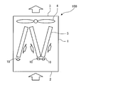
- FIG. 2 is a schematic side view showing the outdoor unit 100 as viewed from one side.
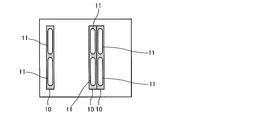
- FIG. 3 is a schematic bottom view showing an example of the outdoor unit 100 as viewed from below.
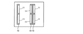
- FIG. 4 is a schematic bottom view showing another example of the outdoor unit 100 as viewed from below.
- FIG. 5 is a schematic bottom view showing still another example of the outdoor unit 100 as viewed from below.
- the outdoor unit 100 will be described with reference to FIGS.
- the outdoor unit 100 is a lower suction blow type outdoor unit.
- the outdoor unit 100 has an outdoor unit housing 1 that forms an outer shell. Inside the outdoor unit housing 1, three heat exchangers 5 are arranged in an inclined state. That is, the heat exchanger 5 is arranged in an N shape when the outdoor unit housing 1 is viewed from the side.
- the heat exchanger 5 is attached to the outdoor unit housing 1 with its upper end and lower end supported by a heat exchanger support member. Moreover, you may support the intermediate branch piping of the heat exchanger 5 with a heat exchanger support member.
- the heat exchanger support member is fixed to the inside of the outdoor unit housing 1 and supports the heat exchanger 5, and is installed in the outdoor unit housing 1 like a beam.
- the fan 4 is arranged inside the outdoor unit housing 1 so as to be positioned above the heat exchanger 5.
- a state in which two fans 4 are arranged is shown as an example, but the number of fans 4 is not particularly limited.
- a suction port 2 serving as an air inlet is provided at the lower part of the outdoor unit housing 1, and an outlet 3 serving as an air outlet is provided at the upper part of the outdoor unit housing 1.
- the inside of the outdoor unit housing 1 is an air passage for air flowing from the suction port 2 toward the blowout port 3.
- a fan 4 and a heat exchanger 5 are installed in a part of the air path of the outdoor unit housing 1.
- a heat exchanger 5 is installed upstream of the fan 4.
- a sheet metal 10 is attached to the lower part of each heat exchanger 5. The sheet metal 10 is attached to suppress variations in fins located on the lower side of the heat exchanger 5.
- the sheet metal 10 is attached so as to come into contact with fins located at the lower part of the heat exchanger 5.
- the total size of the sheet metal 10 is about 0.35 m 2 when the three heat exchangers 5 are arranged in the outdoor unit housing 1.
- Holes 11 through which air passes are formed in the sheet metal 10.
- the hole 11 has an opening ratio of 50% or less of the entire size of the sheet metal 10. As shown in FIG. 3, the hole 11 is configured in an oval shape.
- the shape of the hole 11 formed in the sheet metal 10 may be a rectangular shape with a notch toward the primary side of the air path.
- the air path primary side is the air flowing side of the heat exchanger 5.
- the number of holes 11 formed in the sheet metal 10 may be increased from the number of holes 11 shown in FIGS.
- the holes 11 shown in FIGS. 3 to 5 may be appropriately combined. That is, the design of the number, shape, and size of each hole 11 is not particularly limited. However, the rectangular shape as shown in FIG. 3 or FIG. 4 is less costly than the oval shape.
- the outdoor unit 100 configured as described above, air flows into the outdoor unit housing 1 by driving the fan 4.
- the air sucked into the interior of the outdoor unit housing 1 from the suction port 2 of the outdoor unit housing 1 passes through the sheet metal 10 and the heat exchanger 5 disposed inside the outdoor unit housing 1.
- the air exchanges heat with the refrigerant flowing through the heat exchanger 5 when passing through the heat exchanger 5.
- the heat-exchanged air passes through the fan 4 and is blown out of the outdoor unit housing 1 through the blowout port 3.
- the wind speed on the front surface of the heat exchanger 5 is reduced by 1.1%
- the airway pressure loss is reduced by 1.5%
- the input of the fan 4 can be reduced by 2.3%.
- FIG. FIG. 6 is a schematic side view showing a state in which the outdoor unit 100A of the air-conditioning apparatus according to Embodiment 2 of the present invention is viewed from one side.
- FIG. 7 is a schematic bottom view showing an example of a state in which the outdoor unit 100A is viewed from the lower side.
- the outdoor unit 100A will be described based on FIG. 6 and FIG.
- differences from the first embodiment will be mainly described, and the same parts as those in the first embodiment will be denoted by the same reference numerals and description thereof will be omitted.
- the outdoor unit 100A is a lower suction blow type outdoor unit.
- the outdoor unit 100A has an outdoor unit housing 1A that constitutes an outer shell. Inside the outdoor unit housing 1A, one heat exchanger 5A is arranged in an inclined state. In addition, a fan 4A is disposed inside the outdoor unit housing 1A so as to be positioned above the heat exchanger 5A.
- the number of fans 4A is not particularly limited.
- a suction port 2A serving as an air inlet is provided at the lower part of the outdoor unit housing 1A, and a blower outlet 3A serving as an air outlet is provided at the upper part of the outdoor unit housing 1A. That is, the inside of the outdoor unit housing 1A is an air passage for air flowing from the suction port 2A toward the air outlet 3A.
- the heat exchanger 5A is installed on the upstream side of the fan 4A.
- a sheet metal 10A is attached to the lower part of the heat exchanger 5A. This sheet metal 10A is attached in order to suppress variations in fins located below the heat exchanger 5A.
- a receiver 6 is disposed at the lower part of the outdoor unit housing 1.
- the receiver 6 is installed in a refrigerant circuit included in the air-conditioning apparatus according to Embodiment 2, and temporarily stores the refrigerant.
- the refrigerant circuit included in the air-conditioning apparatus according to Embodiment 2 is configured by connecting a compressor, a heat source side heat exchanger (heat exchanger 5A), a decompression device, and a use side heat exchanger with refrigerant piping through which refrigerant flows.
- the sheet metal 10A is attached so as to come into contact with fins located at the lower part of the heat exchanger 5A.
- the overall size of the sheet metal 10 ⁇ / b> A is about 0.12 m 2 when one heat exchanger 5 is arranged in the outdoor unit housing 1.
- a hole 11A through which air passes is formed in the sheet metal 10A.
- the hole 11A has an opening ratio of 50% or less of the entire size of the sheet metal 10A. As shown in FIG. 7, the hole 11 is configured in an oval shape.
- the shape of the hole 11A formed in the sheet metal 10A may be a rectangular shape having a notch toward the air path primary side.
- the number of holes 11A formed in the sheet metal 10A may be increased from the number of holes 11A in FIG. 7, as shown in FIG. 5 described in the first embodiment.
- the rectangular shape as shown in FIG. 3 or FIG. 4 is less costly than the oval shape.
- the air flows into the outdoor unit housing 1A by driving the fan 4A.
- the air sucked into the interior of the outdoor unit housing 1 from the suction port 2A of the outdoor unit housing 1A passes through the sheet metal 10A and the heat exchanger 5A disposed inside the outdoor unit housing 1A. This air exchanges heat with the refrigerant flowing through the heat exchanger 5A when passing through the heat exchanger 5A.
- the heat-exchanged air passes through the fan 4A and is blown out to the outside of the outdoor unit housing 1A through the blowout port 3A.
- the receiver 6 can be arranged in the internal space of the outdoor unit housing 1A, specifically in the lower space of the heat exchanger 5A.
- the receiver 6 is described as an example, but a compressor, a pump, and the like that circulate the refrigerant can also be disposed in the internal space of the outdoor unit housing 1 ⁇ / b> A in the same manner as the receiver 6.
- Embodiment 1 describes the case where there are three heat exchangers 5 and Embodiment 2 describes the case where there is one heat exchanger 5A, but the number of heat exchangers is not particularly limited.
- 1 outdoor unit housing 1A outdoor unit housing, 2 inlet, 2A inlet, 3 outlet, 3A outlet, 4 fan, 4A fan, 5 heat exchanger, 5A heat exchanger, 6 receiver, 10 sheet metal, 10A sheet metal, 11 holes, 11A holes, 100 outdoor unit, 100A outdoor unit.
Landscapes
- Engineering & Computer Science (AREA)
- Chemical & Material Sciences (AREA)
- Combustion & Propulsion (AREA)
- Mechanical Engineering (AREA)
- General Engineering & Computer Science (AREA)
- Other Air-Conditioning Systems (AREA)
Abstract
La présente invention concerne un climatiseur comprenant une unité extérieure dotée d'un boîtier d'unité extérieure incluant une entrée sur sa partie inférieure et une sortie sur sa partie supérieure, ledit climatiseur comprenant un échangeur de chaleur disposé de manière inclinée à l'intérieur du boîtier d'unité extérieure, ainsi qu'une plaque métallique fixée à la partie inférieure de l'échangeur de chaleur et dans laquelle un orifice permettant le passage de l'air est formé.
Priority Applications (2)
| Application Number | Priority Date | Filing Date | Title |
|---|---|---|---|
| JP2018501440A JPWO2017145253A1 (ja) | 2016-02-23 | 2016-02-23 | 空気調和装置 |
| PCT/JP2016/055147 WO2017145253A1 (fr) | 2016-02-23 | 2016-02-23 | Climatiseur |
Applications Claiming Priority (1)
| Application Number | Priority Date | Filing Date | Title |
|---|---|---|---|
| PCT/JP2016/055147 WO2017145253A1 (fr) | 2016-02-23 | 2016-02-23 | Climatiseur |
Publications (1)
| Publication Number | Publication Date |
|---|---|
| WO2017145253A1 true WO2017145253A1 (fr) | 2017-08-31 |
Family
ID=59684939
Family Applications (1)
| Application Number | Title | Priority Date | Filing Date |
|---|---|---|---|
| PCT/JP2016/055147 Ceased WO2017145253A1 (fr) | 2016-02-23 | 2016-02-23 | Climatiseur |
Country Status (2)
| Country | Link |
|---|---|
| JP (1) | JPWO2017145253A1 (fr) |
| WO (1) | WO2017145253A1 (fr) |
Cited By (2)
| Publication number | Priority date | Publication date | Assignee | Title |
|---|---|---|---|---|
| EP4092339A1 (fr) * | 2021-05-19 | 2022-11-23 | We Heat B.V. | Pompe à chaleur et système de chauffage |
| WO2024069869A1 (fr) * | 2022-09-29 | 2024-04-04 | 日本電気株式会社 | Dispositif d'échange de chaleur et dispositif de réfrigération |
Citations (4)
| Publication number | Priority date | Publication date | Assignee | Title |
|---|---|---|---|---|
| JPS5241564U (fr) * | 1975-09-19 | 1977-03-24 | ||
| JPH03255828A (ja) * | 1990-03-05 | 1991-11-14 | Hitachi Ltd | 空気調和機の室外装置 |
| JP2008075974A (ja) * | 2006-09-21 | 2008-04-03 | Daikin Ind Ltd | 空調ユニット、および空気調和装置の室外ユニット |
| JP2010286157A (ja) * | 2009-06-10 | 2010-12-24 | Mayekawa Mfg Co Ltd | 給湯器 |
-
2016
- 2016-02-23 WO PCT/JP2016/055147 patent/WO2017145253A1/fr not_active Ceased
- 2016-02-23 JP JP2018501440A patent/JPWO2017145253A1/ja active Pending
Patent Citations (4)
| Publication number | Priority date | Publication date | Assignee | Title |
|---|---|---|---|---|
| JPS5241564U (fr) * | 1975-09-19 | 1977-03-24 | ||
| JPH03255828A (ja) * | 1990-03-05 | 1991-11-14 | Hitachi Ltd | 空気調和機の室外装置 |
| JP2008075974A (ja) * | 2006-09-21 | 2008-04-03 | Daikin Ind Ltd | 空調ユニット、および空気調和装置の室外ユニット |
| JP2010286157A (ja) * | 2009-06-10 | 2010-12-24 | Mayekawa Mfg Co Ltd | 給湯器 |
Cited By (3)
| Publication number | Priority date | Publication date | Assignee | Title |
|---|---|---|---|---|
| EP4092339A1 (fr) * | 2021-05-19 | 2022-11-23 | We Heat B.V. | Pompe à chaleur et système de chauffage |
| NL2028240B1 (en) * | 2021-05-19 | 2022-12-05 | We Heat B V | Heat pump and heating system. |
| WO2024069869A1 (fr) * | 2022-09-29 | 2024-04-04 | 日本電気株式会社 | Dispositif d'échange de chaleur et dispositif de réfrigération |
Also Published As
| Publication number | Publication date |
|---|---|
| JPWO2017145253A1 (ja) | 2018-09-13 |
Similar Documents
| Publication | Publication Date | Title |
|---|---|---|
| JP2014016084A (ja) | 空気調和機の室外ユニット | |
| JP6223596B2 (ja) | 空気調和装置の室内機 | |
| US9863651B2 (en) | Outdoor unit for air-conditioning apparatus | |
| CN111197818A (zh) | 一种空调室外机及中央空调 | |
| US10047963B2 (en) | Indoor unit for air-conditioning apparatus | |
| JP2016200338A (ja) | 空気調和機 | |
| WO2017145253A1 (fr) | Climatiseur | |
| JP6400378B2 (ja) | 空気調和機 | |
| WO2016151755A1 (fr) | Climatiseur | |
| JP2008267637A (ja) | 冷凍空調装置 | |
| JP6390271B2 (ja) | 空気調和装置の室外ユニット | |
| JP2014228223A (ja) | 空気調和機 | |
| US11365892B2 (en) | Heat exchanger and indoor unit having the same | |
| JP2010196945A (ja) | 室外ユニット | |
| JP2010216750A (ja) | 空気調和機 | |
| JP4734915B2 (ja) | 熱交換器およびそれを備えた空気調和機の室内機 | |
| JP2017009149A (ja) | 空気調和機 | |
| JP6451752B2 (ja) | 空気調和装置の室内側ユニット | |
| JP2015175567A (ja) | 天井埋込型空気調和機 | |
| JP6104384B2 (ja) | 空気調和機 | |
| US9689577B2 (en) | Outdoor unit for air-conditioning apparatus | |
| JP4918282B2 (ja) | 室内機および空気調和機 | |
| JP2017138008A (ja) | 熱交換器 | |
| JP6547130B2 (ja) | 空気調和機 | |
| JP6429991B2 (ja) | 空気調和装置 |
Legal Events
| Date | Code | Title | Description |
|---|---|---|---|
| ENP | Entry into the national phase |
Ref document number: 2018501440 Country of ref document: JP Kind code of ref document: A |
|
| NENP | Non-entry into the national phase |
Ref country code: DE |
|
| 121 | Ep: the epo has been informed by wipo that ep was designated in this application |
Ref document number: 16891412 Country of ref document: EP Kind code of ref document: A1 |
|
| 122 | Ep: pct application non-entry in european phase |
Ref document number: 16891412 Country of ref document: EP Kind code of ref document: A1 |