WO2017145272A1 - データ移行方法及び計算機システム - Google Patents
データ移行方法及び計算機システム Download PDFInfo
- Publication number
- WO2017145272A1 WO2017145272A1 PCT/JP2016/055329 JP2016055329W WO2017145272A1 WO 2017145272 A1 WO2017145272 A1 WO 2017145272A1 JP 2016055329 W JP2016055329 W JP 2016055329W WO 2017145272 A1 WO2017145272 A1 WO 2017145272A1
- Authority
- WO
- WIPO (PCT)
- Prior art keywords
- migration
- virtual
- copy
- instruction
- logical volume
- Prior art date
- Legal status (The legal status is an assumption and is not a legal conclusion. Google has not performed a legal analysis and makes no representation as to the accuracy of the status listed.)
- Ceased
Links
Images




Classifications
-
- G—PHYSICS
- G06—COMPUTING OR CALCULATING; COUNTING
- G06F—ELECTRIC DIGITAL DATA PROCESSING
- G06F3/00—Input arrangements for transferring data to be processed into a form capable of being handled by the computer; Output arrangements for transferring data from processing unit to output unit, e.g. interface arrangements
- G06F3/06—Digital input from, or digital output to, record carriers, e.g. RAID, emulated record carriers or networked record carriers
- G06F3/0601—Interfaces specially adapted for storage systems
- G06F3/0602—Interfaces specially adapted for storage systems specifically adapted to achieve a particular effect
- G06F3/0614—Improving the reliability of storage systems
- G06F3/0619—Improving the reliability of storage systems in relation to data integrity, e.g. data losses, bit errors
-
- G—PHYSICS
- G06—COMPUTING OR CALCULATING; COUNTING
- G06F—ELECTRIC DIGITAL DATA PROCESSING
- G06F3/00—Input arrangements for transferring data to be processed into a form capable of being handled by the computer; Output arrangements for transferring data from processing unit to output unit, e.g. interface arrangements
- G06F3/06—Digital input from, or digital output to, record carriers, e.g. RAID, emulated record carriers or networked record carriers
- G06F3/0601—Interfaces specially adapted for storage systems
- G06F3/0602—Interfaces specially adapted for storage systems specifically adapted to achieve a particular effect
- G06F3/061—Improving I/O performance
-
- G—PHYSICS
- G06—COMPUTING OR CALCULATING; COUNTING
- G06F—ELECTRIC DIGITAL DATA PROCESSING
- G06F3/00—Input arrangements for transferring data to be processed into a form capable of being handled by the computer; Output arrangements for transferring data from processing unit to output unit, e.g. interface arrangements
- G06F3/06—Digital input from, or digital output to, record carriers, e.g. RAID, emulated record carriers or networked record carriers
- G06F3/0601—Interfaces specially adapted for storage systems
- G06F3/0628—Interfaces specially adapted for storage systems making use of a particular technique
- G06F3/0646—Horizontal data movement in storage systems, i.e. moving data in between storage devices or systems
- G06F3/0647—Migration mechanisms
-
- G—PHYSICS
- G06—COMPUTING OR CALCULATING; COUNTING
- G06F—ELECTRIC DIGITAL DATA PROCESSING
- G06F3/00—Input arrangements for transferring data to be processed into a form capable of being handled by the computer; Output arrangements for transferring data from processing unit to output unit, e.g. interface arrangements
- G06F3/06—Digital input from, or digital output to, record carriers, e.g. RAID, emulated record carriers or networked record carriers
- G06F3/0601—Interfaces specially adapted for storage systems
- G06F3/0628—Interfaces specially adapted for storage systems making use of a particular technique
- G06F3/0646—Horizontal data movement in storage systems, i.e. moving data in between storage devices or systems
- G06F3/065—Replication mechanisms
-
- G—PHYSICS
- G06—COMPUTING OR CALCULATING; COUNTING
- G06F—ELECTRIC DIGITAL DATA PROCESSING
- G06F3/00—Input arrangements for transferring data to be processed into a form capable of being handled by the computer; Output arrangements for transferring data from processing unit to output unit, e.g. interface arrangements
- G06F3/06—Digital input from, or digital output to, record carriers, e.g. RAID, emulated record carriers or networked record carriers
- G06F3/0601—Interfaces specially adapted for storage systems
- G06F3/0628—Interfaces specially adapted for storage systems making use of a particular technique
- G06F3/0662—Virtualisation aspects
- G06F3/0665—Virtualisation aspects at area level, e.g. provisioning of virtual or logical volumes
-
- G—PHYSICS
- G06—COMPUTING OR CALCULATING; COUNTING
- G06F—ELECTRIC DIGITAL DATA PROCESSING
- G06F3/00—Input arrangements for transferring data to be processed into a form capable of being handled by the computer; Output arrangements for transferring data from processing unit to output unit, e.g. interface arrangements
- G06F3/06—Digital input from, or digital output to, record carriers, e.g. RAID, emulated record carriers or networked record carriers
- G06F3/0601—Interfaces specially adapted for storage systems
- G06F3/0668—Interfaces specially adapted for storage systems adopting a particular infrastructure
- G06F3/067—Distributed or networked storage systems, e.g. storage area networks [SAN], network attached storage [NAS]
Definitions
- the present invention generally relates to data migration.
- Data migration is performed in the computer system.
- One purpose of data migration is migration of a storage device.
- a storage device For example, it is conceivable to use the technique disclosed in Patent Document 1 for migration of the storage apparatus.
- a heterogeneous storage is connected to an existing storage, and data management information of the heterogeneous storage is set in the existing storage. If this technology is used for migration of storage devices, it can be expected that the migration source storage device is connected to the migration destination storage device and the migration is realized without stopping the migration source storage device for a long time.
- SDx Software-defined xxx
- SDC Software-defined Computing
- the SDx for storage is SDS (Software-defined Storage).
- the SDS is virtual storage, that is, hardware-independent storage.
- the SDS may be an example of software that operates on a physical device or a virtual device, or may be an example of a virtual device itself.
- the “physical device” is a device having a plurality of physical resources including a physical processor and a physical memory, for example, a physical computer such as a general-purpose server.
- the “virtual device” is a device having a plurality of virtual resources (for example, a virtual processor and a virtual memory) based on a plurality of physical resources, and is, for example, an LPAR (Logical Partition) or a VM (Virtual Machine).
- SDS migration is performed in the same manner as storage device migration.
- the reason why SDS migration is performed is, for example, replacement with SDS having a new function or change of an SDS vendor.
- Patent Document 1 If the technology of Patent Document 1 is used for migration of SDS, it can be expected that the migration source SDS is connected to the migration destination SDS and the migration is realized without stopping the migration source SDS for a long time.
- An instruction to associate the second logical volume with the second virtual storage that is the migration destination of the first virtual storage that provides the first logical volume is transmitted.
- the first virtual storage is a virtual storage to which a virtual resource provided by the virtual management unit is allocated.
- a copy instruction that is an instruction to copy data to the second logical volume is transmitted from one of the first logical volume and the copy source logical volume.
- copy completion which is completion of data copy to the second logical volume
- an erase instruction that is an instruction to erase the first virtual storage is transmitted to the virtual management unit.
- Example 1 shows a configuration of a computer system according to a first embodiment.
- the structure of a migration management table is shown.
- the structure of copy information is shown. It is a sequence diagram of a transfer destination SDS construction process. It is a sequence diagram of a copy preparation process. It is a sequence diagram of an access destination switching process.
- 6 is a sequence diagram of migration source SDS erasure processing according to Embodiment 1.
- FIG. The outline of Example 2 is shown.
- FIG. 10 is a sequence diagram of parallel remote copy processing according to the second embodiment.
- FIG. 10 is a sequence diagram of migration source SDS erasure processing according to Embodiment 2.
- the outline of Example 3 is shown.
- FIG. 10 is a sequence diagram of PVOL update status notification processing according to the third embodiment.
- FIG. 10 is a sequence diagram of internal copy processing according to the third embodiment.
- FIG. 10 is a sequence diagram of migration source SDS erasure processing according to Embodiment 3.
- the “physical device” is a device having a plurality of physical resources including a physical processor and a physical memory, for example, a physical computer such as a general-purpose server.
- the “virtual device” is a device having a plurality of virtual resources (for example, a virtual processor and a virtual memory) based on a plurality of physical resources, and is, for example, an LPAR (Logical Partition) or a VM (Virtual Machine).
- “Processor” means at least one of a physical processor and a virtual processor.
- “Memory” means at least one of physical memory and virtual memory.
- Interface means at least one of a physical interface and a virtual interface.
- the process may be described using “program” as a subject.
- the program is executed by a processor so that a predetermined process is appropriately performed by at least one of a memory and an interface. Therefore, the subject of processing may be a processor (or a physical device or a virtual device having a processor).
- the program may be installed in the computer from a program source.
- the program source may be, for example, a program distribution server or a computer-readable recording medium.
- two or more programs may be realized as one program, or one program may be realized as two or more programs.
- information may be described using expressions such as “xxx table” and “xxx bitmap”, but the information may be expressed in any data structure. That is, in order to show that the information does not depend on the data structure, the “xxx table” and the “xxx bitmap” can be referred to as “xxx information”, respectively.
- the configuration of the table is an example, and one table may be divided into two or more tables, or all or part of the two or more tables may be one table. (This may also be true for bitmaps).
- a reference code (or a common part in the reference sign) is used, and when explaining the same kind of element separately, the element ID (or Element reference signs) may be used.
- VOL is an abbreviation for logical volume.
- the VOL may be a logical volume based on one or more physical storage devices (or one or more virtual storage devices), or may be a virtual logical volume according to Thin Provisioning.
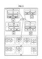
- FIG. 1 shows an outline of the first embodiment.
- the computer system 100 includes a virtual management unit 22, a migration source SDS 14, a migration source VOL 26S, a management VM (Virtual Machine) 18, and a host 10.
- the virtual management unit 22 is a virtualization program (for example, a hypervisor) that provides virtualized resources.
- the virtual management unit 22 is a base that virtually shows a physical server, and is a cloud base as an example.
- the virtual management unit 22 can also provide a device to which the virtualized resource is allocated in addition to the virtualized resource.
- Each of the migration source SDS 14, the management VM 18, and the host 10 is a VM created by the virtual management unit 22.
- a VM is an example of a virtual device.
- a migration manager 20 is installed in the management VM 18.
- the migration source SDS 14 is an example of a first virtual storage.
- the migration source VOL 26S is an example of a first logical volume.
- the virtual management unit 22 may be a physical processor that executes the virtualization program as described above (specifically, the virtual management unit 22 may be realized by the virtual processor executing the virtualization program), or virtualization.
- An apparatus for example, a module including a memory in which a program is held and a physical processor that executes a virtualization program may be used.
- the migration source VOL 26S is associated with the migration source SDS 14 (for example, mounted).
- the migration source VOL 26S is provided to the host 10 by the migration source SDS 14.
- the migration source SDS 14 receives an I / O (Input / Output) request specifying the ID (identification information) of the migration source VOL 26S from the host 10, the migration source SDS 14 sends an I / O according to the received I / O request to the migration source VOL 26S. (Ie, reading data from the migration source VOL 26S or writing data to the migration source VOL 26S).
- the ID of the migration source VOL 26S includes, for example, the volume number (for example, LUN (Logical Unit Unit Number)) of the migration source VOL 26S.
- the migration manager 20 transmits an instruction to create the migration destination SDS 16 to the virtual management unit 22.
- the virtual management unit 22 constructs the migration destination SDS 16 in the computer system 100 in which the migration source SDS 14 exists.
- the reason for SDS migration is the change of the SDS vendor, and therefore the vendor of the migration source SDS 14 and the vendor of the migration destination SDS 16 are different. However, these vendors may be the same vendor.
- the migration destination VOL 26D is associated with the migration destination SDS 16.
- the migration destination SDS 16 is an example of a second virtual storage.
- the migration destination VOL 26D is an example of a second logical volume.
- the migration manager 20 instructs the migration destination SDS 16 and the migration source SDS 14 so that the migration source SDS 16 can access the migration source SDS 14.
- target information which is information including the ID of the migration source VOL 26S is associated with the migration destination VOL 26D. That is, the migration source VOL 26S is mapped (associated) to the migration destination SDS 16 via the migration source SDS 14 in accordance with the storage virtualization technology.
- the association of a VOL with another storage via a storage may be referred to as “external connection” for convenience.
- the migration manager 20 instructs the host 10 to change the access destination from the migration source SDS 14 to the migration destination SDS 16.
- the migration destination SDS 16 receives the I / O request specifying the ID of the migration source VOL 26S.
- the migration destination SDS 16 executes the migration source VOL 26D.
- the migration manager 20 transmits a copy instruction to copy the data of the migration source VOL 26S to the migration destination VOL 26D to at least one of the migration source SDS 14 and the migration destination SDS 16.
- the data stored in the migration source VOL 26S is copied to the migration destination VOL 26D via the migration source SDS 14 and the migration destination SDS 16. That is, data copying from the migration source VOLS 26S to the migration destination VOL 26D is performed.
- the migration destination SDS 16 accepts an I / O request specifying the ID of the migration source VOL 26S from the host 10, and sends the I / O according to the received I / O request to the migration source VOL 26D. Can be executed.
- gray blocks represent data.
- the block diagram of step 2 in FIG. 1 means that a part of the data in the migration source VOL 26S has been copied to the migration destination VOL 26D.
- the copy completion is detected.
- the “copy completed” mentioned here may be that there is no difference between the contents of the migration source VOL 26S and the contents of the migration destination VOL 26D, in other words, the contents of the migration source VOL 26S and the contents of the migration destination VOL 26D match.
- the migration manager 20 receives a copy completion notification from at least one of the migration source SDS 14 and the migration destination SDS 16. More specifically, for example, the migration manager 20 transmits a data copy progress inquiry to at least one of the migration source SDS 14 and the migration destination SDS 16, and sends a response to the query to the migration source SDS 14 and the migration destination. The copy completion is detected based on the response received from at least one of the SDSs 16 (the transmission destination of the inquiry).
- the migration manager 20 transmits to the virtual management unit 22 an erasure instruction that is an instruction to erase the migration source SDS 14 and the migration source VOL 26S.
- the virtual management unit 22 deletes the migration source SDS 14 and the migration source VOL 26S.
- the virtual manager 22 may erase all the virtual resources allocated to the migration source SDS 14 from the migration source SDS 14 and then erase the migration source SDS 14, or as a result of erasure of the migration source SDS 14, the migration source SDS 14 All the virtual resources allocated to may be released.
- the migration destination VOL 26D when the migration destination VOL 26D is associated with the migration destination SDS 16, and copying from the migration source VOL 26S to the migration destination VOL 26D is completed, the migration source SDS 14 and the migration source VOL 26S do not need to be maintained. Can be positioned. For this reason, the migration source SDS 14 and the migration source VOL 26S can be deleted. Thereby, reduction of at least one of resources and costs can be expected. It is sufficient that at least the migration source SDS 14 is erased, but further reduction can be expected by erasing the migration source VOL 26S.
- the migration manager 20 can collectively manage the migration process, and can finally erase the migration source SDS 14 without stopping the migration source SDS 14 for a long time. Therefore, SDS migration can be facilitated and the SDS operation cost can be expected to be reduced.
- external connection is adopted, but external connection is not essential.
- external connection is not essential.
- the switching of the access destination VOL of the host 10 is performed before the start of copying (before transmission of the copy instruction), but may be performed during copying or after completion of copying.
- the switching of the access destination VOL is performed before the start of copying as described above.
- FIG. 2 shows the configuration of the computer system 100.
- the computer system 100 has a physical resource group 200 and executes the virtual management unit 22.
- the virtual management unit 22 manages a virtual resource group 210 that is a plurality of resources in which at least a part of the physical resource group 200 is virtualized.
- the VM to which at least a part of the virtual resource group 210 is allocated is created by the virtual management unit 22.
- the physical resource group 200 is a plurality of physical resources including a plurality of types of physical resources.
- Examples of the physical resource include at least one of a physical processor (for example, CPU (Central Processing Unit)) 148, a physical memory 146, a physical storage device 126, and a physical interface (not shown).
- the virtual resource group 210 is a plurality of virtual resources including a plurality of types of virtual resources. Examples of the virtual resource include at least one of a virtual processor 48, a virtual memory 46, a VOL 26, a virtual interface (not shown), and a virtual network 36.
- the virtual resource may be based on the same type of physical resource as the type of virtual resource or may be based on a type of physical resource different from the type of virtual resource.
- At least one physical processor executes the virtual management unit 22.
- the virtual management unit 22 is an example of a virtualization program, and is, for example, a hypervisor.
- the virtual manager 22 can create or delete a VM.
- Each VM is equipped with one or more virtual processors 48, one or more virtual memories 46, and one or more virtual interfaces (not shown), and one or more VOLs 46 are mounted.
- the virtual interface is an interface for communication performed through the virtual network 36.
- Each VM executes a guest OS (Operating System) 50.
- the host 10, the management VM 18, the migration source SDS 14, and the migration destination SDS 16 are VMs created and managed by the virtual management unit 22.
- the host 10 and the management VM 18 may be physical devices connected to the computer system 100, or may be virtual devices in a computer system (not shown) connected to the computer system 100.
- the migration destination SDS 16 may be constructed in a computer system (not shown) connected to the computer system 100.
- the migration source SDS 14 includes a virtual processor 48S, a virtual memory 46S, a guest OS 50S, and the like, and a storage control program (hereinafter, migration source program) 51S is installed.
- the migration source program 51S controls the operation of the migration source SDS14. For example, in accordance with an I / O request from the host 10, I / O is performed on the migration source VOL 26S.
- the guest OS 50S and the migration source program 51S are executed by the virtual processor 48S.
- a migration source VOL 26S is mounted on the migration source SDS.
- the migration destination SDS 16 includes a virtual processor 48D, a virtual memory 46D, a guest OS 50D, and the like, and a storage control program (hereinafter, migration destination program) 51D is installed.
- the migration destination program 51D logically holds copy information 47 for managing the data copy progress status from the migration source VOL 26S to the migration destination VOL 26D.
- the copy information 47 is stored in the virtual memory 46D.
- the guest OS 50D and the migration destination program 51D are executed by the virtual processor 48D.
- the migration destination VOL 26D is mounted on the migration destination SDS16.
- the copy information 47 may be held by the migration manager 20 of the management VM 18.
- the migration destination SDS 16 may have the same architecture as the migration source SDS 14. Further, the amount of virtual resources of the migration destination SDS 16 may be the same as or different from the amount of virtual resources of the migration source SDS 14. Further, the migration destination program 51D may have a new function that is not present in the migration source program 51S, or has a part of the functions (for example, functions that are less necessary) of the migration source program 51S. You don't have to. Further, the capacity of the migration destination VOL 26D associated with the migration destination SDS 16 is the same as the capacity of the migration source VOL 26S, but these capacities may be different.
- the host 106 includes a virtual processor 48H, a virtual memory 46H, a guest OS 50H, and the like, and the VOL 26H is mounted.
- the management VM 18 includes a virtual processor 48M, a virtual memory 46M, a guest OS 50M, and the like, and the migration manager 20 is installed.
- the migration manager 20 logically holds a migration management table 45 in which addresses of modules that can become communication partners of the migration manager 20 are recorded.
- the migration management table 45 is stored in the virtual memory 46M.
- a VOL 26M is mounted on the management VM 18.
- the management VM 18, the host 10, the migration source SDS 14, the migration destination SDS 16, and the virtual management unit 22 are connected to the virtual network 36A. Communication is performed via the virtual network 36A. Communication between VMs is performed via the virtual network 36A. The virtual management unit 22 may further pass through communication between VMs.
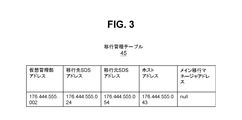
- FIG. 3 shows the configuration of the migration management table 45.
- the migration management table 45 holds the address of the virtual management unit 22, the address of the migration destination SDS 16, the address of the migration source SDS 14, the address of the host 10, and the address of the main migration manager.
- the value of the unnecessary address is an invalid value (for example, “null”).
- the value of the main migration manager address is “null” (the main migration manager will be described in the second and third embodiments).
- the migration manager 20 identifies the address of the instruction destination from the migration management table 45, and issues an instruction to the instruction destination via the virtual network 36A using the identified address.
- the address recorded in the migration management table 45 is an address on the virtual network 36A, and may be, for example, the port number of the virtual network switch.
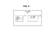
- FIG. 4 shows the configuration of the copy information 47.
- the copy information 47 includes copy progress rate information 61 and a copy progress bit map 62.
- the copy progress rate information 61 represents the copy progress rate from the migration source VOL 26S to the migration destination VOL 26D.
- the copy progress rate “100%” means that the copy is completed.
- the copy progress rate is updated by the transfer destination program 51D according to the copy progress.
- the copy progress bitmap 62 has a plurality of bits respectively corresponding to a plurality of VOL areas constituting the migration destination VOL 26D. If the VOL area corresponding to the bit has not yet been copied, the bit is “0”. On the other hand, if the copying is completed for the VOL area corresponding to the bit, the bit is “1”.
- Copying from the migration source VOL 26S to the migration destination VOL 26D may be performed for each VOL area.
- the bit is updated from “0” to “1” by the migration destination program 51D.
- the migration destination program 51D calculates the copy progress rate based on the copy progress bit map 62 and updates the copy progress rate information 61.
- the copy information 47 may be held by the migration manager 20 of the management VM 18. In this case, the migration manager 20 stores the copy progress rate information 61 based on a response to the data copy progress inquiry. Update.
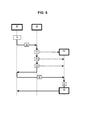
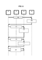
- FIG. 5 is a sequence diagram of the migration destination SDS construction process. The process of FIG. 5 corresponds to the details of step 1 of FIG.
- Step 74 The migration manager 20 starts by input from the user (for example, an administrator) (for example, instructions for creating the migration destination SDS 16) or detection of the migration start time (for example, migration is performed as necessary) The management table 45 is updated). Proceed to step 76.
- the user for example, an administrator
- the migration start time for example, migration is performed as necessary
- Step 76 The migration manager 20 transmits a creation instruction to create a new VM (VM for the migration destination SDS 16) 62 to the virtual management unit 22.
- the migration manager 20 determines a migration destination specification based on at least one of the configuration information and usage status of the migration source SDS 14, and information indicating the determined migration destination specification is sent to the virtual management unit 22. It may be included in the creation instruction.
- the “migration destination specification” is a specification of the migration destination SDS, and may be, for example, at least one of the capacity of the migration destination VOL 26D and the configuration and amount of the virtual resource allocated to the new VM 62.
- the migration manager 20 may acquire at least one of the configuration information and the usage status of the migration source SDS 14 from the migration source SDS 14. Proceed to step 77.
- Step 77 The virtual management unit 22 creates a new VM 62 in response to the creation instruction from the migration manager 20. At this stage, for example, at least one of virtual resources including a virtual processor and a virtual memory may be allocated to the new VM 62. At this stage, the guest OS may be loaded on the new VM 62. Proceed to step 78.
- Step 78 Next, the virtual management unit 22 associates the migration destination VOL 26D with the new VM 62.
- the capacity of the migration source VOL 26S is, for example, a capacity according to the migration destination specification included in the creation instruction.
- the capacity of the migration source VOL 26S is the same as the capacity of the migration source VOL 26S as described above, but it may be a capacity that provides a performance higher than that of the migration source SDS 14, or a capacity according to the usage amount of the migration source VOL 26S. It may be said. Proceed to step 79.
- Step 79 The virtual management unit 22 allocates a virtual network to the new VM 62.
- the virtual network may be a virtual network switch having the same subnet mask so that the migration source SDS 14, the host 10, and the management VM 18 can be accessed, for example. Thereafter, the virtual manager 22 notifies the migration manager 20 of the completion of processing as a response to the creation instruction. Proceed to step 80.
- Step 80 The migration manager 20 transmits an installation instruction for installing the migration destination program 51D to the new VM 62.
- the installation instruction may include the migration destination program 51D, or may include a link (for example, URL) to the download source of the migration destination program 51D. As described above, the migration destination program 51D may not be the same as the migration source program 51S. Proceed to step 82.
- Step 82 The new VM 62 (eg, guest OS) installs the migration destination program 51D in response to the installation instruction.
- the new VM 62 in which the migration destination program 51D is installed and the migration destination VOL 26D is associated becomes the migration destination SDS 16.
- the new VM 62 notifies the migration manager 20 of the completion of processing as a response to the installation instruction. When the migration manager 20 receives this processing completion, the flow of FIG. 6 is started.
- FIG. 6 is a sequence diagram of the copy preparation process. The process of FIG. 6 corresponds to some details of step 2 of FIG.
- Step 98 The migration manager 20 transmits a permission instruction, which is an instruction for permitting access from the migration destination SDS 16 to the migration source VOL 26S, to the migration source SDS 14. Proceed to step 100.
- a permission instruction which is an instruction for permitting access from the migration destination SDS 16 to the migration source VOL 26S, to the migration source SDS 14. Proceed to step 100.
- Step 100 In response to the permission instruction, the migration source SDS 14 (migration source program 51S) sets target information including the identification information of the migration source VOL 26S and the identification information of the virtual port to which the migration source VOL 26S belongs.
- the protocol of the virtual network may be FC (Fiber Channel), iSCSI or the like.
- the migration source SDS 14 notifies the migration manager 20 of the completion of processing as a response to the permission instruction. Proceed to step 102.
- the process completion includes the set target information.
- Step 102 The migration manager 20 transmits to the migration destination SDS 16 an external connection instruction that is an instruction for associating the migration source VOL 26S with the migration destination SDS 16 via the migration source SDS 14. Proceed to step 104.
- the external connection instruction includes target information included in the process completion.
- Step 104 The migration destination SDS 16 (migration destination program 51D) recognizes the migration source VOL 26S by registering the target information of the migration source SDS 14 in response to the external connection instruction. That is, the migration source VOL 26S is associated with the migration destination SDS 16.
- the migration destination SDS 16 may poll the port of the migration destination SDS 16, or may restart the guest OS of the migration destination SDS 16.
- the migration destination SDS 16 notifies the migration manager 20 of the completion of processing as a response to the external connection instruction. Proceed to step 108.
- Step 108 The migration manager 20 transmits to the migration destination SDS 16 a preparation instruction that is an instruction for preparing a copy from the migration source VOL 26S to the migration destination VOL 26D. Proceed to step 110.
- Step 110 The migration destination SDS 16 creates the copy information 47 in response to the preparation instruction.
- the copy progress rate information 61 represents the copy progress rate “0%”, and all the bits constituting the copy progress bit map 62 are “0”.
- the migration destination SDS 16 notifies the migration manager 20 of the completion of processing as a response to the preparation instruction. Proceed to step 114.
- Step 114 The migration manager 20 transmits a copy progress rate query to the migration destination SDS 16 regularly or irregularly, and receives a copy progress rate response as a response to the query. In parallel with the process at step 114, the process at step 124 in FIG. 7 is performed.
- the migration destination SDS 16 may notify the migration manager 20 of the copy progress rate periodically or irregularly without receiving an inquiry from the migration manager 20, or the copy progress rate is set to “100%”.
- the migration manager 20 may be notified of the completion of copying when it is detected that it has become. In any case, the migration manager 20 can determine from the information from the migration destination SDS 16 whether copy has been completed.
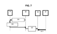
- FIG. 7 is a sequence diagram of the access destination switching process. The process of FIG. 7 may be performed in parallel with step 114 after step 110 is completed. 7 corresponds to another part of Step 2 in FIG.
- Step 124 The migration manager 20 sends a notification of the address of the migration destination SDS 16 (address on the virtual network) to the host 10. Proceed to step 126.
- Step 126 In response to the notification of the address, the host 10 switches the access destination address from the address of the migration source SDS 14 to the address of the migration destination SDS 16. The switching may be performed manually or by a server agent executed on the host 10. Thereafter, as a response to the address notification, the host 10 notifies the migration manager 20 of the completion of the processing. Proceed to step 127.
- Step 127 The migration manager 20 transmits a VOL migration instruction to the migration destination SDS 16.
- VOL migration instruction for example, migration source information (information including identification information of the migration source VOL 26S) and migration destination information (information including identification information of the migration destination VOL 26D) are designated.
- the migration destination SDS 16 performs copying from the migration source VOL 26S to the migration destination VOL 26D.
- the copy information 47 is updated by the migration destination SDS 16 according to the progress of copying. For example, it is assumed that data is newly written from the host 10 to the migration destination VOL 26D.
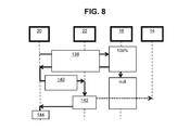
- FIG. 8 is a sequence diagram of the migration source SDS erasing process. The process in FIG. 8 corresponds to step 3 in FIG.
- Step 138 The migration manager 20 transmits a copy progress rate inquiry to the migration destination SDS 16 regularly or irregularly, and receives an answer to the inquiry from the migration destination SDS 16. If the copy progress rate indicated by the received reply is not “100%”, the migration manager 20 transmits a copy progress rate query to the migration destination SDS 16 again after a certain time, for example. If the copy progress rate indicated by the received response is “100%”, this corresponds to the detection of copy completion. Proceed to step 140. When copy completion is detected (for example, when a copy progress rate “100%” is returned and confirmation is received from the migration manager 20), the migration destination SDS 16 indicates the copy progress rate represented by the copy progress rate information 61. , “100%” is updated to “null”.
- Step 140 The migration manager 20 transmits an instruction to delete the migration source SDS 14 and the migration source VOL 26S to the virtual management unit 22. Proceed to step 142.
- Step 142 In response to the deletion instruction, the virtual management unit 22 deletes the migration source SDS 14 and the migration source VOL 26S.
- virtual resources such as virtual memory allocated to the migration source SDS 14 are released (can be allocated to other VMs), and the virtual device (migration) is managed from the management target of the virtual management unit 22.
- the VM as the original SDS 14 is also released. Therefore, when the migration source SDS 14 itself is released from the management target of the virtual management unit 22, the VM as the migration source SDS 14 is also deleted from the management target of the management VM 18.
- the virtual manager 22 notifies the migration manager 20 of the completion of processing as a response to the erasure instruction. Proceed to step 144.
- Step 144 The migration manager 20 ends the process.
- SDS is an example of a VM to which virtualized resources are allocated. SDS itself cannot secure or release resources.
- the migration manager 20 that transmits an instruction that can be interpreted by the virtual manager 22 that provides virtual resources and controls generation and deletion of VMs is provided separately. Due to the cooperation between the migration manager 20 and the virtual management unit 22 (the instruction from the migration manager 20 and the operation of the virtual management unit 22 in response to the instruction), the migration destination VOL 26D is associated with the migration destination SDS 16, and the migration source VOL 26S The data is copied to the migration destination VOL 26D, and after the completion of the copy is detected, the migration source SDS itself including the virtual resource allocated to the migration source SDS 14 can be released. As a result, the utilization efficiency of resources can be improved, and the costs for virtual resources and SDS management can be reduced.
- Example 2 will be described. Differences from the first embodiment will be mainly described, and description of common points with the first embodiment will be omitted or simplified.
- FIG. 9 shows an outline of Example 2.
- the computer system 100M in the main site 900M includes the migration source storage 152.
- the backup source PVOL 154 is mounted on the migration source storage 152.
- the migration source storage 152 may be an SDS or an example of a physical device.
- a system including at least one of the migration source storage 152 and the migration destination storage 150 described later is hereinafter collectively referred to as “main storage”.
- PVOL is an abbreviation for primary VOL, and is an example of a copy source logical volume of the first logical volume.
- a host 901 exists in the main site 900M.
- the computer system 100R at the remote site 900R has a virtual management unit 22.
- the SVOL 26S is an abbreviation for the secondary VOL, is an example of the first logical volume, and corresponds to the above-described migration source VOL.
- a pair of PVOL154 and SVOL26S is configured.
- Data is remote copied (backup copy) from PVOL154 to SVOL26S.
- the pair of PVOL 154 and SVOL 26S may be a synchronous pair or an asynchronous pair.
- “Synchronous pair” means that when data newly written to PVOL 154 according to an I / O request from host 901 (“data X” in this paragraph) is copied to SVOL 26S, the response to the I / O request is sent to host The pair returns to 901.
- Data X has been written to PVOL 154 means that data X has actually been written to PVOL 154, but data X may have been written to the cache memory of the main storage.
- “The data X has been copied to the SVOL 26S” means that the data X has actually been written to the SVOL 26S, but it is stored in the cache memory (at least a part of the virtual memory 46S) of the migration source SDS 14. Data X may be written.
- the “asynchronous pair” is a pair in which a response to the I / O request is returned to the host 901 when data X is newly written to the PVOL 154 in accordance with an I / O request from the host 901 (SVOL 26S of data X May be done after the response is returned).
- Example 2 in addition to the migration from the migration source SDS 14 to the migration destination SDS 16 at the remote site 900R, the migration from the migration source storage 152 to the migration destination storage 150 is performed at the main site 900M.
- the PVOL 154 is associated with the migration destination storage 150 via the migration source storage 152. Therefore, when the migration destination storage 150 receives an I / O request specifying the identification information of the PVOL 154 via a network (for example, a LAN (Local Area Network)) 912, the I / O according to the I / O request is This is executed via the migration destination storage 150 and the migration source storage 152.
- the network 912 may be a physical communication network or a virtual network.
- the main storage is managed by the main migration manager 20M executed by the management server 18M.
- the management server 18M may be an example of a physical device or an example of a virtual device.
- the main migration manager 20M is a computer program that manages the main storage.
- the remote site 900R has a management VM 18R.
- the migration manager executed by the management VM 18R is referred to as “remote migration manager”.
- the remote migration manager 20R issues an instruction to the virtual management unit 22 to create the migration destination SDS 16.
- the migration destination SDS 16 is associated with the migration destination SVOL 26D.
- the migration destination SVOL 26D is an example of a second logical volume, is a migration destination of the SVOL 26S, and corresponds to the migration destination VOL described above.
- the computer system 100M may include a virtual management unit.
- a virtual system in which at least one of the host 901, the network 912, the migration source storage 152, the migration destination storage 150152, and the management server 18M is generated or managed by the virtual management unit. It may be an element.
- the computer systems 100M and 100R are connected via a network (hereinafter referred to as an inter-system network).
- Remote copy is performed via an inter-system network (for example, LAN or WAN (WideWArea Network)).
- an inter-system network for example, LAN or WAN (WideWArea Network)
- the remote copy from the PVOL 154 to the SVOL 26S is performed via the migration source storage 152, the inter-system network (not shown), and the migration source SDS 14 before the migration of the migration source storage 152 and the migration source SDS 14, respectively.
- the migration destination SDS 16 is created in response to an instruction from the remote migration manager 20R.
- the PVOL 154 is associated with the migration destination storage 150 via the migration source storage 152 (external connection of POVL 154).
- the main migration manager 20M instructs the migration destination storage 150 to perform remote copy (parallel data backup) from the PVOL 154 to the migration destination SVOL 26D.
- parallel remote copy parallel data backup
- the PVOL 154 and the migration destination SVOL 26D may be paired. That is, in addition to the pair of PVOL 154 and SVOL 26S, there may be a pair of PVOL 154 and migration destination SVOL 26D.
- remote copy from the PVOL 154 to the SVOL 26S is performed via the migration source storage 152, the inter-system network (not shown), and the migration source SDS 14.
- Parallel remote copy from the PVOL 154 to the migration destination SVOL 26D is performed via the migration source storage 152, the migration destination storage 150, the inter-system network (not shown), and the migration destination SDS 16.
- the main migration manager 20M transmits a pair split instruction that is an instruction to split the pair of the PVOL 154 and the SVOL 26S to the transfer source storage 152.
- the remote migration manager 20R transmits an instruction to delete the migration source SDS 14 and the SVOL 26S to the virtual management unit 22.
- the virtual management unit 22 deletes the migration source SDS 14 and the SVOL 26S.
- the second embodiment at the time of introducing remote copy (data backup), it can be expected that at least one of resources and costs is reduced by deleting the migration source SDS 14 and the migration source SVOL 26S.
- the SDS migration can be performed without stopping the remote copy from the PVOL 154 to the SVOL 26S, it is possible to execute the SDS migration at the remote site 900R regardless of whether the pair of the PVOL 154 and the SVOL 26S is a synchronous pair or an asynchronous pair. is there.
- the vendor of the migration source SDS 14 and the vendor of the migration destination SDS 16 are different, and the vendor of the migration destination storage 150 and the vendor of the migration destination SDS 16 are the same.
- the processing performed in the second embodiment includes all of the processing in FIG. 5, a part of the processing in FIG. 6 (from step 98 to step 104), parallel remote copy, and deletion of the migration source SDS 14 and SVOL 26S. .
- the SVOL 26S may be associated with the migration destination SDS 16. However, even in that case, at least until the concurrent remote copy is completed, the migration source is used to continue the remote copy from the PVOL 154 to the SVOL 26S (for example, without stopping the I / O request acceptance from the host 901). SDS 14 is necessary.
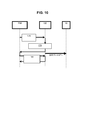
- FIG. 10 is a sequence diagram of parallel remote copy processing according to the second embodiment.
- Step 176 The main migration manager 20M transmits a parallel remote copy instruction to the migration destination storage 150.
- the parallel remote copy instruction is an instruction to start a parallel remote copy from the PVOL 154 to the migration destination SVOL 26D (a remote copy performed in parallel with the remote copy from the PVOL 154 to the SVOL 26S). Proceed to step 178.
- Step 178 In response to the parallel remote copy start instruction, the migration destination storage 150 starts the parallel remote copy and updates the copy information 47 according to the progress of the copy.
- the migration destination storage 150 and the migration destination SDS 16 holds and updates the copy information.
- at least one of the main migration manager 20M and the remote migration manager 20R may hold and update the copy information.
- the copy information includes first copy information related to the first remote copy from the PVOL 154 to the SVOL 26S, and second copy information related to the second remote copy (parallel remote copy) from the PVOL 154 to the migration destination SVOL 26D. At least second copy information may be included.
- the configuration of each of the first and second copy information may be the same as the configuration of the copy information 47 described above. That is, the first copy information is a first copy progress rate information representing the first copy progress rate, which is a progress rate related to the first remote copy, and a bitmap representing a difference between the PVOL 154 and the SVOL 26S. And a first copy progress bitmap.
- the second copy information is a second copy progress rate information representing the second copy progress rate, which is the progress rate of the second remote copy, and a bitmap representing the difference between the PVOL 154 and the migration destination SVOL 26D. And a second copy progress bitmap. If all the bits of the first copy progress bitmap are “1”, the first copy progress rate is “100%”.
- the migration destination storage 150 notifies the main migration manager 20M of the completion of processing. Proceed to step 180.
- Step 180 The main migration manager 20M sends an inquiry about at least the second copy progress rate of the first and second copy progress rates to the migration destination storage 150 regularly or irregularly, and A response of the second copy progress rate is received as a response to the inquiry.
- the migration destination storage 150 may notify the main migration manager 20M of at least the second copy progress rate periodically or irregularly without receiving an inquiry from the main migration manager 20M.
- the completion of parallel remote copy may be notified to the main migration manager 20M when it is detected that the copy progress rate of “100%” has reached “100%”. In any case, the main migration manager 20M can know from the information from the migration destination storage 150 whether or not the parallel remote copy has been completed.
- FIG. 11 is a sequence diagram of the migration source SDS erasing process according to the second embodiment.
- Step 202 The main migration manager 20M transmits a second copy progress rate query to the migration destination storage 150 regularly or irregularly, and receives an answer to the query from the migration destination storage 150. If the second copy progress rate indicated by the received reply is not “100%”, the main migration manager 20M transmits the second copy progress rate query to the migration destination storage 150 again after a certain time, for example. If the second copy progress rate indicated by the received response is “100%”, this corresponds to the detection of the completion of the parallel remote copy. Proceed to step 204. When the completion of the parallel remote copy is detected (for example, when the second copy progress rate “100%” is answered and confirmation is received from the main migration manager 20M), the migration destination storage 150 receives the second copy. The second copy progress rate represented by the progress rate information is updated from “100%” to “null”.
- Step 204 The main migration manager 20M transmits a pair split instruction which is an instruction to split the pair of the PVOL 154 and the SVOL 26S to at least one of the transfer source storage 152 and the transfer destination storage 150.
- the pair split instruction is transmitted to the migration source storage 152. Proceed to step 206.
- Step 206 In response to the pair split instruction, the migration source storage 152 splits the pair of PVOL 154 and SVOL 26S. As a result, the first remote copy stops. That is, even if there is a difference between the PVOL 154 and the SVOL 26S, the remote copy from the PVOL 154 to the SVOL 26S is not performed.
- the migration source storage 152 notifies the main migration manager 20M of the completion of processing as a response to the pair split instruction. Proceed to step 208.
- Step 208 The main migration manager 20M notifies the remote migration manager 20R of the completion of the main site processing. Proceed to step 210. Thereafter, the process proceeds to step 214, and the main migration manager 20M ends the process (step 214).
- Step 211 The remote migration manager 20R transmits an instruction to delete the migration source SDS 14 and the SVOL 26S to the virtual management unit 22 in response to the notification of the completion of the main site processing. That is, the reception of the notification of the completion of the main site process is the detection of the completion of the parallel remote copy for the remote migration manager 20R. Proceed to step 212.
- Step 212 The virtual management unit 22 deletes the migration source SDS 14 and the SVOL 26S in response to the deletion instruction.
- the virtual manager 22 notifies the remote migration manager 20R of the completion of processing as a response to the erasure instruction. Thereafter, the process proceeds to step 216, and the remote migration manager 20R ends the process (step 216).
- Example 3 will be described. Differences from the second embodiment will be mainly described, and description of common points with the second embodiment will be omitted or simplified.
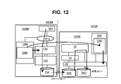
- FIG. 12 shows an outline of Example 3.
- first pair that is a pair of PVOL154 and SVOL26S
- second pair that is a pair of SVOL26S and migration destination SVOL26D.
- an internal copy that is a data copy from the SVOL 26S to the migration destination SVOL 26D is performed.
- the remote migration manager 20R instructs at least one of the virtual management unit 22, the migration source SDS 14, and the migration destination SDS 16 to perform internal copy from the SVOL 26S to the migration destination SVOL 26D.
- an internal copy (for example, an internal copy via the migration source SDS 14 and the migration destination SDS 16) from the SVOL 26S to the migration destination SVOL 26D is executed.
- the migration source SDS 14 and the SVOL 26S are deleted.
- the communication band between the main site 900M and the remote site 900R (communication band of an inter-system network (not shown)) can be saved as compared with the second embodiment.
- the first pair (PVOL 154 and SVOL 26S) is a synchronous pair, but the first pair may be an asynchronous pair.
- a host write bitmap (not shown) is prepared.
- the host write bitmap indicates in which VOL area of the PVOL 154 data has been written.
- the host write bitmap has a plurality of bits respectively corresponding to a plurality of VOL areas constituting the PVOL 154.
- the bit corresponding to the VOL area in which data is newly written is set to “1”.
- the host write bitmap is held and updated by the migration destination storage 150.
- the host write bitmap is held in both the migration destination storage 150 and the main migration manager 20M.
- the host write bitmap possessed by the migration destination storage 150 and the host write bitmap possessed by the main migration manager 20M may be synchronized.
- FIG. 13 is a sequence diagram of the PVOL update status notification process according to the third embodiment.
- the “PVOL update status notification process” is a process for notifying the update status of the PVOL 154.
- the reason why this processing is necessary is that when data is newly written to the PVOL 154 and newly copied to the copied area (VOL area in the SVOL 26S and the internal copy has been completed), the copy is performed again. This is because an internal copy is required for the completed area.
- the main migration manager 20M periodically or irregularly responds to an inquiry from the remote migration manager 20R (or without an inquiry), and updates the PVOL update status from the migration destination storage 150 holding the host write bitmap. Identify and notify the remote migration manager 20R.
- the notified PVOL update status may be a copy of the host write bitmap held by the main migration manager 20M, or information including the ID (for example, address) of the updated VOL area.
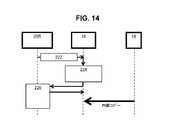
- FIG. 14 is a sequence diagram of internal copy processing according to the third embodiment.
- Step 222 The remote migration manager 20R transmits an internal copy start instruction to the migration destination SDS 16. Proceed to step 224.
- Step 224 In response to the internal copy start instruction, the migration destination SDS 16 starts an internal copy from the SVOL 26S to the migration destination SVOL 26D, and updates the copy information 47 according to the progress of the internal copy.
- the migration destination SDS 16 notifies the remote migration manager 20R of the completion of processing as a response to the internal copy start instruction. Proceed to step 226.
- Step 226 The remote migration manager 20R refers to the PVOL update status (information specified based on the host write bitmap).
- the remote migration manager 20R notifies the migration destination SDS 16 of an additional internal copy instruction that specifies the address of the target location if there is a target location (VOL area) that is a location where additional internal copying must be performed, and The bit corresponding to the target location (bit in the host write bitmap held by the remote migration manager 20R) is updated from “1” to “0”.
- data is copied from the VOL area in the SVOL 26S (VOL area corresponding to the target location address) to the VOL area in the migration destination SVOL 26D (VOL area corresponding to the target location address) ( Additional internal copy).
- the update of the bit corresponding to the target location is notified from the remote migration manager 20R to the main migration manager 20M through the communication shown in FIG. 13, and the main migration manager 20M receives the bit corresponding to the target location (the main migration manager 20M Bit in the host write bit map held by "1" is updated from “1" to "0". This update is also reflected in the host write bitmap that the migration destination storage 150 has.
- Step 226 is repeated regularly or irregularly until the internal copy is complete.
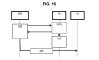
- FIG. 15 is a sequence diagram of the migration source SDS erasing process according to the third embodiment.
- Step 246 The remote migration manager 20R periodically or irregularly transmits a copy progress rate (internal copy progress rate) query to the migration destination SDS 16, and receives a response to the query from the migration destination SDS 16. If the copy progress rate indicated by the received response is “100%”, the remote migration manager 20R refers to the host write bitmap and determines whether or not an additional internal copy is necessary. If so, an additional internal copy and accompanying host write bitmap update is performed. If not, the process proceeds to step 248. When starting Step 246, the main migration manager 20M may temporarily stop receiving an I / O request (for example, a write request) specifying the PVOL 154 from the host 901 to the migration destination storage 150. Then, when step 246 is completed, the main migration manager 20M may cause the migration destination storage 150 to release the temporary suspension.
- I / O request for example, a write request
- Step 248 The remote migration manager 20R transmits to the migration source SDS 14 a pair division instruction for dividing the pair of the PVOL 154 and the SVOL 26S. In response to the pair split instruction, step 206 and subsequent steps in FIG. 11 may be performed. Note that the remote migration manager 20R instructs the main migration manager 20M to divide the pair, and the main migration manager 20M sends a pair division instruction for dividing the pair of the PVOL 154 and the SVOL 26S in response to the instruction. You may transmit to 152.
- the migration destination SVOL 26D that has been migrated in the third embodiment may perform a pair operation with the PVOL 154 (may be paired with the PVOL 154) or may be retained as backup data (paired with the PVOL 154). May be independent).
- each of the migration source SDS 14 and the migration destination SDS 16 is a VM.
- the migration source SDS 14 may be software executed by the first VM
- the migration destination SDS 16 may be software executed by the second VM.
- the first and second VMs may be configured to execute the same type of first and second guest OSs provided by the virtual management unit 22, respectively.
- the migration manager 20 (20 ⁇ / b> R) may transmit the deletion instruction of the migration source SDS 14 to the first VM without passing through the virtual management unit 22 or may transmit it to the virtual management unit 22.
- the first guest OS may receive the deletion instruction from the migration manager 20 (20R) or the virtual management unit 22, and may delete the migration source SDS 14 in response to the deletion instruction.
- At least one of the migration manager 20, the main migration manager 20M, and the remote migration manager 20R may be installed from the program source.
- the program source may be a recording medium (for example, a non-transitory recording medium) that can be read by a program distribution server or a computer.
Landscapes
- Engineering & Computer Science (AREA)
- Theoretical Computer Science (AREA)
- Human Computer Interaction (AREA)
- Physics & Mathematics (AREA)
- General Engineering & Computer Science (AREA)
- General Physics & Mathematics (AREA)
- Computer Security & Cryptography (AREA)
- Information Retrieval, Db Structures And Fs Structures Therefor (AREA)
Abstract
Description
Claims (14)
- 第1論理ボリュームを提供する第1仮想ストレージの移行先である第2仮想ストレージに第2論理ボリュームを関連付ける指示を送信し、前記第1仮想ストレージは、仮想管理部により提供された仮想リソースが割り当てられた仮想ストレージであり、
前記第1論理ボリュームと前記第1論理ボリュームのコピー元論理ボリュームとのうちのいずれか一方から前記第2論理ボリュームにデータをコピーすることの指示であるコピー指示を送信し、
前記第2論理ボリュームへのデータコピーの完了であるコピー完了を検出した場合に、前記第1仮想ストレージを消去することの指示である消去指示を、前記仮想管理部に送信する、
データ移行方法。 - 前記コピー指示の送信先は、前記第1仮想ストレージ及び前記第2仮想ストレージのうちの少なくとも1つであり、
前記コピー完了の検出は、前記第1仮想ストレージ及び前記第2仮想ストレージのうちの少なくとも1つから前記コピー完了の通知を受信することである、
請求項1記載のデータ移行方法。 - 前記仮想管理部が、前記消去指示に応答して、前記第1仮想ストレージを消去する、
請求項1記載のデータ移行方法。 - 前記第2仮想ストレージは、前記仮想管理部に前記第2仮想ストレージの作成指示を送信することにより生成された仮想ストレージである、
請求項1記載のデータ移行方法。 - ホストからのI/Oが前記第2論理ボリュームで受けつけられつつ前記データコピーが行われるようにするために、前記第2論理ボリュームに前記第1論理ボリュームのターゲット情報を関連付けることで前記第2論理ボリュームに前記第1論理ボリュームをマッピングする、
請求項1記載のデータ移行方法。 - 前記データコピーの進捗の問合せを、前記第1仮想ストレージ及び前記第2仮想ストレージのうちの少なくとも1つに送信し、
前記問合せに対する応答を、前記第1仮想ストレージ及び前記第2仮想ストレージのうちの少なくとも1つから受信し、
前記コピー完了は、前記受信した応答を基に検出される、
請求項1記載のデータ移行方法。 - 前記第1仮想ストレージに仮想リソースを提供する前記仮想管理部を有する第1計算機システムにネットワーク経由で接続され移行元ストレージ装置を有する第2計算機システムが存在し、
前記第1論理ボリュームは、前記移行元ストレージ装置によって提供されるプライマリボリュームとコピーペアを形成するセカンダリボリュームであり、
前記コピー元論理ボリュームは、前記プライマリボリュームである、
請求項1記載のデータ移行方法。 - 前記第2論理ボリュームへのコピーは、前記プライマリボリュームから行われ、
前記第1計算機システムの管理プログラムが実行されることにより実現される第1移行マネージャが、前記第2計算機システムの管理プログラムが実行されることにより実現される第2移行マネージャと通信可能であり、
前記第1移行マネージャが、前記第2論理ボリュームへのデータコピーの完了を検出した前記第2移行マネージャからの指示に応答して、前記仮想管理部に前記消去指示を送信する、
請求項7記載のデータ移行方法。 - 前記データコピーと並行して、前記プライマリボリュームから前記セカンダリボリュームへのデータのコピーが行われる、
請求項7記載のデータ移行方法。 - 前記仮想管理部は、物理プロセッサが仮想化プログラムを実行することで実現される、
請求項1記載のデータ移行方法。 - 仮想リソースを提供する仮想管理部と、
移行マネージャと
を有し、
前記移行マネージャは、
第1論理ボリュームを提供する第1仮想ストレージの移行先である第2仮想ストレージに第2論理ボリュームを関連付けることの指示を送信し、前記第1仮想ストレージは、仮想管理部により提供された仮想リソースが割り当てられた仮想ストレージであり、
前記第1論理ボリュームと前記第1論理ボリュームのコピー元論理ボリュームとのうちのいずれか一方から前記第2論理ボリュームにデータをコピーすることの指示であるコピー指示を送信し、
前記第2論理ボリュームへのデータコピーの完了であるコピー完了を検出した場合に、前記第1仮想ストレージを消去することの指示である消去指示を、前記仮想管理部に送信し、
前記仮想管理部が、前記消去指示に応答して、前記第1仮想ストレージを消去する、
計算機システム。 - 第1論理ボリュームを提供する第1仮想ストレージの移行先である第2仮想ストレージに第2論理ボリュームを関連付けることの指示を送信し、前記第1仮想ストレージは、仮想管理部により提供された仮想リソースが割り当てられた仮想ストレージであり、
前記第1論理ボリュームと前記第1論理ボリュームのコピー元論理ボリュームとのうちのいずれか一方から前記第2論理ボリュームにデータをコピーすることの指示であるコピー指示を送信し、
前記第2論理ボリュームへのデータコピーの完了であるコピー完了を検出した場合に、前記第1仮想ストレージを消去することの指示である消去指示を、前記仮想管理部に送信する、
ことをコンピュータに実行させるためのコンピュータプログラムを記録したコンピュータ読取り可能な記録媒体。 - 前記コピー指示の送信先は、前記第1仮想ストレージ及び前記第2仮想ストレージのうちの少なくとも1つであり、
前記コピー完了の検出は、前記第1仮想ストレージ及び前記第2仮想ストレージのうちの少なくとも1つから前記コピー完了の通知を受信することである、
請求項12記載の記録媒体。 - 前記第2仮想ストレージは、前記仮想管理部に前記第2仮想ストレージの作成指示を送信することにより生成された仮想ストレージである、
請求項12記載の記録媒体。
Priority Applications (3)
| Application Number | Priority Date | Filing Date | Title |
|---|---|---|---|
| JP2018501456A JP6663478B2 (ja) | 2016-02-24 | 2016-02-24 | データ移行方法及び計算機システム |
| PCT/JP2016/055329 WO2017145272A1 (ja) | 2016-02-24 | 2016-02-24 | データ移行方法及び計算機システム |
| US15/546,124 US10496294B2 (en) | 2016-02-24 | 2016-02-24 | Data migration method and computer system |
Applications Claiming Priority (1)
| Application Number | Priority Date | Filing Date | Title |
|---|---|---|---|
| PCT/JP2016/055329 WO2017145272A1 (ja) | 2016-02-24 | 2016-02-24 | データ移行方法及び計算機システム |
Publications (1)
| Publication Number | Publication Date |
|---|---|
| WO2017145272A1 true WO2017145272A1 (ja) | 2017-08-31 |
Family
ID=59685020
Family Applications (1)
| Application Number | Title | Priority Date | Filing Date |
|---|---|---|---|
| PCT/JP2016/055329 Ceased WO2017145272A1 (ja) | 2016-02-24 | 2016-02-24 | データ移行方法及び計算機システム |
Country Status (3)
| Country | Link |
|---|---|
| US (1) | US10496294B2 (ja) |
| JP (1) | JP6663478B2 (ja) |
| WO (1) | WO2017145272A1 (ja) |
Cited By (4)
| Publication number | Priority date | Publication date | Assignee | Title |
|---|---|---|---|---|
| JP2020027433A (ja) * | 2018-08-10 | 2020-02-20 | 株式会社日立製作所 | 情報システム |
| JP2021504795A (ja) * | 2017-11-24 | 2021-02-15 | アリババ・グループ・ホールディング・リミテッドAlibaba Group Holding Limited | クラウドサービス移行のための方法、装置、及び電子デバイス |
| JP2023073197A (ja) * | 2021-11-15 | 2023-05-25 | 株式会社日立製作所 | 情報処理システム及び方法 |
| JP2024027156A (ja) * | 2021-11-15 | 2024-02-29 | 株式会社日立製作所 | 情報処理システム及び方法 |
Families Citing this family (7)
| Publication number | Priority date | Publication date | Assignee | Title |
|---|---|---|---|---|
| CN106201659B (zh) * | 2016-07-12 | 2019-07-05 | 腾讯科技(深圳)有限公司 | 一种虚拟机热迁移的方法及宿主机 |
| JP2018010507A (ja) * | 2016-07-14 | 2018-01-18 | 富士通株式会社 | メモリ管理プログラム、メモリ管理方法及びメモリ管理装置 |
| US10572271B1 (en) | 2018-08-29 | 2020-02-25 | Red Hat, Inc. | Efficient instantiation of encrypted guests |
| US10768837B2 (en) * | 2018-10-31 | 2020-09-08 | EMC IP Holding Company LLC | Non-disruptive migration of a virtual volume in a clustered data storage system |
| US12242751B2 (en) * | 2023-03-03 | 2025-03-04 | SanDisk Technologies, Inc. | Data storage device and method for host-assisted efficient handling of multiple versions of data |
| JP2024164659A (ja) * | 2023-05-15 | 2024-11-27 | トヨタ自動車株式会社 | 車両データの管理方法及び管理装置 |
| JP7825604B2 (ja) * | 2023-11-30 | 2026-03-06 | 日立ヴァンタラ株式会社 | ストレージシステム及び記憶制御方法 |
Citations (2)
| Publication number | Priority date | Publication date | Assignee | Title |
|---|---|---|---|---|
| JP2007310861A (ja) * | 2006-04-18 | 2007-11-29 | Hitachi Ltd | ストレージシステム及びその制御方法 |
| JP2009217466A (ja) * | 2008-03-10 | 2009-09-24 | Hitachi Ltd | ストレージ装置、計算機システム及びデータ管理方法 |
Family Cites Families (5)
| Publication number | Priority date | Publication date | Assignee | Title |
|---|---|---|---|---|
| JP3671595B2 (ja) | 1997-04-01 | 2005-07-13 | 株式会社日立製作所 | 複合計算機システムおよび複合i/oシステム |
| JP4282464B2 (ja) * | 2003-12-17 | 2009-06-24 | 株式会社日立製作所 | リモートコピーシステム |
| WO2012143965A1 (en) * | 2011-04-18 | 2012-10-26 | Hitachi, Ltd. | Plurality of coupled storage subsystems and method for setting port access limitation in a storage subsystem when migrating a logical volume |
| JP2013029911A (ja) * | 2011-07-27 | 2013-02-07 | Fujitsu Ltd | 制御装置、制御方法およびストレージ装置 |
| US8935496B2 (en) * | 2012-08-31 | 2015-01-13 | Hitachi, Ltd. | Management method of virtual storage system and remote copy system |
-
2016
- 2016-02-24 JP JP2018501456A patent/JP6663478B2/ja not_active Expired - Fee Related
- 2016-02-24 WO PCT/JP2016/055329 patent/WO2017145272A1/ja not_active Ceased
- 2016-02-24 US US15/546,124 patent/US10496294B2/en active Active
Patent Citations (2)
| Publication number | Priority date | Publication date | Assignee | Title |
|---|---|---|---|---|
| JP2007310861A (ja) * | 2006-04-18 | 2007-11-29 | Hitachi Ltd | ストレージシステム及びその制御方法 |
| JP2009217466A (ja) * | 2008-03-10 | 2009-09-24 | Hitachi Ltd | ストレージ装置、計算機システム及びデータ管理方法 |
Cited By (8)
| Publication number | Priority date | Publication date | Assignee | Title |
|---|---|---|---|---|
| JP2021504795A (ja) * | 2017-11-24 | 2021-02-15 | アリババ・グループ・ホールディング・リミテッドAlibaba Group Holding Limited | クラウドサービス移行のための方法、装置、及び電子デバイス |
| JP7624167B2 (ja) | 2017-11-24 | 2025-01-30 | アリババ・グループ・ホールディング・リミテッド | クラウドサービス移行のための方法、装置、及び電子デバイス |
| JP2020027433A (ja) * | 2018-08-10 | 2020-02-20 | 株式会社日立製作所 | 情報システム |
| JP7113698B2 (ja) | 2018-08-10 | 2022-08-05 | 株式会社日立製作所 | 情報システム |
| JP2023073197A (ja) * | 2021-11-15 | 2023-05-25 | 株式会社日立製作所 | 情報処理システム及び方法 |
| JP7413458B2 (ja) | 2021-11-15 | 2024-01-15 | 株式会社日立製作所 | 情報処理システム及び方法 |
| JP2024027156A (ja) * | 2021-11-15 | 2024-02-29 | 株式会社日立製作所 | 情報処理システム及び方法 |
| JP7648731B2 (ja) | 2021-11-15 | 2025-03-18 | 日立ヴァンタラ株式会社 | 情報処理システム及び方法 |
Also Published As
| Publication number | Publication date |
|---|---|
| JP6663478B2 (ja) | 2020-03-11 |
| JPWO2017145272A1 (ja) | 2018-08-30 |
| US20180121112A1 (en) | 2018-05-03 |
| US10496294B2 (en) | 2019-12-03 |
Similar Documents
| Publication | Publication Date | Title |
|---|---|---|
| JP6663478B2 (ja) | データ移行方法及び計算機システム | |
| US10713074B2 (en) | Method, apparatus, and system for accessing storage device | |
| US10817333B2 (en) | Managing memory in devices that host virtual machines and have shared memory | |
| US8402220B2 (en) | Storage controller coupled to storage apparatus | |
| JP5459811B2 (ja) | 仮想ストレージ移行のための方法およびシステム、ならびに仮想マシンモニタ | |
| JP5427574B2 (ja) | 仮想計算機の移動管理方法、前記移動管理方法を用いた計算機、前記移動管理方法を用いた仮想化機構および前記移動管理方法を用いた計算機システム | |
| US8954706B2 (en) | Storage apparatus, computer system, and control method for storage apparatus | |
| US20190012110A1 (en) | Information processing apparatus, and control method of information processing system | |
| US10289564B2 (en) | Computer and memory region management method | |
| JP5718533B1 (ja) | ストレージシステムのデータ移行方法 | |
| WO2019061352A1 (zh) | 数据加载方法及装置 | |
| US8516209B2 (en) | Computer system, storage volume management method, and computer-readable storage medium | |
| CN107003893A (zh) | 虚拟机备份方法、备份装置及宿主机 | |
| US20100275203A1 (en) | Storage management system and storage management method in virtualization environment | |
| WO2019071431A1 (zh) | 处理i/o请求的方法、设备及主机 | |
| US20210034245A1 (en) | Techniques for capturing virtual machine snapshots using data storage system snapshots | |
| US20160259559A1 (en) | Storage system and control method thereof | |
| CN104636159A (zh) | 对虚拟机中的软件进行升级的方法和装置 | |
| US20190073150A1 (en) | Storage management server, method of controlling storage management server, and computer system | |
| US20120324039A1 (en) | Computer system and disk sharing method used thereby | |
| CN107832097B (zh) | 数据加载方法及装置 | |
| JP7113698B2 (ja) | 情報システム | |
| CN120188180A (zh) | 借助直接连接的非易失性存储器快速设备的虚拟机实时迁移 | |
| US10848405B2 (en) | Reporting progress of operation executing on unreachable host | |
| US12124336B2 (en) | Data acquisition of snapshots |
Legal Events
| Date | Code | Title | Description |
|---|---|---|---|
| WWE | Wipo information: entry into national phase |
Ref document number: 15546124 Country of ref document: US |
|
| ENP | Entry into the national phase |
Ref document number: 2018501456 Country of ref document: JP Kind code of ref document: A |
|
| NENP | Non-entry into the national phase |
Ref country code: DE |
|
| 121 | Ep: the epo has been informed by wipo that ep was designated in this application |
Ref document number: 16891429 Country of ref document: EP Kind code of ref document: A1 |
|
| 122 | Ep: pct application non-entry in european phase |
Ref document number: 16891429 Country of ref document: EP Kind code of ref document: A1 |