WO2017145326A1 - Boîtier, unité de boîtier, et procédé de fabrication d'unité de boîtier - Google Patents
Boîtier, unité de boîtier, et procédé de fabrication d'unité de boîtier Download PDFInfo
- Publication number
- WO2017145326A1 WO2017145326A1 PCT/JP2016/055632 JP2016055632W WO2017145326A1 WO 2017145326 A1 WO2017145326 A1 WO 2017145326A1 JP 2016055632 W JP2016055632 W JP 2016055632W WO 2017145326 A1 WO2017145326 A1 WO 2017145326A1
- Authority
- WO
- WIPO (PCT)
- Prior art keywords
- case
- placement
- mounting
- mounting surface
- surface portion
- Prior art date
- Legal status (The legal status is an assumption and is not a legal conclusion. Google has not performed a legal analysis and makes no representation as to the accuracy of the status listed.)
- Ceased
Links
Images

Classifications
-
- H—ELECTRICITY
- H05—ELECTRIC TECHNIQUES NOT OTHERWISE PROVIDED FOR
- H05K—PRINTED CIRCUITS; CASINGS OR CONSTRUCTIONAL DETAILS OF ELECTRIC APPARATUS; MANUFACTURE OF ASSEMBLAGES OF ELECTRICAL COMPONENTS
- H05K5/00—Casings, cabinets or drawers for electric apparatus
-
- H—ELECTRICITY
- H05—ELECTRIC TECHNIQUES NOT OTHERWISE PROVIDED FOR
- H05K—PRINTED CIRCUITS; CASINGS OR CONSTRUCTIONAL DETAILS OF ELECTRIC APPARATUS; MANUFACTURE OF ASSEMBLAGES OF ELECTRICAL COMPONENTS
- H05K5/00—Casings, cabinets or drawers for electric apparatus
- H05K5/04—Metal casings
Definitions
- the present invention relates to a case, a case unit, and a method for manufacturing the case unit.
- a case unit in which an object to be stored such as a substrate is accommodated in a case and the substrate is sealed with a resin injected into the case.
- a hybrid integrated circuit device case unit in which a substrate is fixed to a stepped portion (mounting surface) formed on the inner periphery of a case and a resin is filled on the mounting surface so as to cover the substrate is disclosed in Patent Literature 1 is disclosed.
- the mounting surface in order to improve the adhesion between the substrate and the mounting surface, the mounting surface is subjected to cutting to increase the surface accuracy of the mounting surface (to reduce the surface roughness).
- the inner surface is connected to the outer periphery of the mounting surface. For this reason, when the mounting surface is cut, the inner surface of the case is also cut by the cutting process, and the surface roughness of the inner surface of the case is also reduced. As a result, the adhesion between the resin and the inner surface of the case may not be ensured. In this case, for example, moisture may enter between the inner side surface of the case and the resin, and moisture may reach the substrate, which is not preferable.
- An object of the present invention is to provide a case, a case unit, and a method of manufacturing the case unit that can ensure the adhesion between the resin and the case even if the surface accuracy of the mounting surface is improved.
- a mounting surface on which at least a peripheral portion of an object to be stored is mounted, and an inner surface extending in a circumferential direction so as to surround the outer periphery of the object to be stored, connected to the outer periphery of the mounting surface.
- the inner side surface is connected to the first surface portion with the first surface portion being connected to the mounting surface and extending in the circumferential direction, and the first surface portion sandwiched between the mounting surface.
- the step surface portion extending in the circumferential direction and extending in a direction away from the outer periphery of the mounting surface, and the step surface portion is sandwiched between the first surface portion and connected to the step surface portion, and extends in the circumferential direction.
- a second surface portion that is located farther from the placement surface than the surface portion, and the first surface portion and the placement surface are cases having a smaller surface roughness than the second surface portion.
- the case according to the above aspect the object to be accommodated accommodated in the case so that at least the peripheral edge portion is placed on the placement surface, and the second surface portion are in contact with the case. And a resin unit that seals an object to be stored in the case.
- the third aspect of the present invention has a placement surface on which at least a peripheral portion of the object to be placed is placed, and an inner surface connected to the outer periphery of the placement surface, and the placement surface among the inner surfaces.
- the forming step of forming a case in which a portion in the vicinity of the boundary protrudes toward the inner peripheral side, and the placement surface described above until the inner peripheral side portion of the inner surface protrudes toward the inner peripheral side is cut Cutting the surface to reduce the surface roughness of the mounting surface, and after the cutting step, placing the object to be stored on the mounting surface so that the peripheral edge contacts the mounting surface. It is a manufacturing method of a case unit provided with the mounting process and the sealing process of sealing the storage object with resin in the state where the storage object was mounted on the mounting surface mentioned above.
- the surface of the second surface portion is rougher than the mounting surface while improving the surface accuracy of the mounting surface.
- the case and the case unit of the present invention have the adhesiveness between the resin portion and the second surface portion when the accommodation object is sealed by the resin portion in a state where the accommodation object is placed on the placement surface. Is expensive.
- the adhesion between the resin and the case can be ensured even if the surface accuracy of the placement surface is increased.
- the case unit manufacturing method of the present invention even if the boundary portion between the inner surface and the mounting surface is cut in the process of cutting the mounting surface, the portion of the inner surface away from the boundary portion is not yet removed. Remains in the cutting state. For this reason, according to the manufacturing method of the case unit of the present invention, it is possible to manufacture a case unit with high surface accuracy of the mounting surface and high adhesion between the resin and the case.
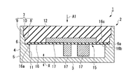
- the case unit 1 of this embodiment is a unit in which the accommodation object 15 is accommodated.
- a circuit board 16 on which an electronic component 17 is mounted is shown as an example of the accommodation object 15.
- the circuit board 16 exemplified in this embodiment has lands, wiring patterns, and the like for mounting the electronic component 17.
- the peripheral edge portion 16a of the circuit board 16 has a flat surface as a portion that comes into contact with the mounting surface 6 described later.
- the case unit 1 of the present embodiment includes a case 2, the above-described accommodation object 15, and a resin portion 12.
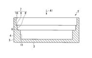
- the case 2 is formed in a bottomed cylindrical shape (container shape) having a bottom 3 and a side wall 4. Case 2 is made of metal. The bottom 3 and the side wall 4 constitute a space for accommodating the object 15 to be accommodated.
- the bottom 3 has, for example, a flat plate shape.
- the shape of the bottom 3 may be set as appropriate in accordance with the shape of the accommodation object 15.
- the side wall 4 extends substantially perpendicularly from the outer periphery of the bottom portion 3 in the thickness direction of the bottom portion 3 (the direction indicated by the symbol X in FIG. 1), and extends continuously along the outer periphery of the bottom portion 3.
- the side wall 4 is formed in a cylindrical shape.
- the outer surface of the side wall 4 constitutes the outer surface 5 of the case 2.
- the shape of the outer side surface 5 may be appropriately set in consideration of the design and heat dissipation of the case 2 or the shape of the target to which the case 2 is attached.
- the inner surface of the side wall 4 has a mounting surface 6, a first inner side surface 7, and a second inner side surface 11.
- the placement surface 6 is a surface on which the peripheral edge portion 16a of the accommodation target 15 is placed.
- the mounting surface 6 in the present embodiment has a planar shape.
- the placement surface 6 has high surface accuracy so that the gap between the placement surface 6 and the object to be stored 15 is reduced.
- the placement surface 6 has “high surface accuracy” when the placement surface 6 is relatively high compared to the surface accuracy of the second surface portion 10 (described later) of the first inner surface 7. It means having accuracy.
- the surface accuracy of the mounting surface 6 in the present embodiment includes, for example, arithmetic average roughness (Ra), maximum height (Ry), ten-point average roughness (Rz), average interval of unevenness (Sm), and local summit It can be represented by parameters indicating surface roughness such as average spacing (S) and load length ratio (tp).
- the surface roughness of the mounting surface 6 of the present embodiment is smaller than the surface roughness of the second surface portion 10 described later.
- the mounting surface 6 should just have a surface precision higher than the 2nd surface part 10 at least. If the surface accuracy of the mounting surface 6 is sufficiently high, processing for increasing the surface accuracy of the mounting surface 6 is not essential.
- the mounting surface 6 has a relatively high surface accuracy with respect to the second surface portion 10 due to the relative surface accuracy being generated by roughing the second surface portion 10. May be.
- the peripheral edge portion 16a of the object 15 is fixed to the placement surface 6 with an adhesive or the like. Since the surface accuracy of the mounting surface 6 is high, a gap between the mounting surface 6 and the peripheral portion 16a of the object to be stored 15 can be eliminated or reduced.
- the first inner surface 7 has a first surface portion 8, a step surface portion 9, and a second surface portion 10.
- the first surface portion 8 is connected to the placement surface 6 and extends in a direction (circumferential direction) surrounding the outer periphery of the object 15 to be stored.
- the first surface portion 8 extends from the outer periphery of the placement surface 6 substantially perpendicularly to the placement surface 6.
- the first surface portion 8 has a shape that follows the outer periphery of the accommodation target 15 placed on the placement surface 6.
- the first surface portion 8 has a surface accuracy equivalent to the surface accuracy of the mounting surface 6. In the first surface portion 8, only the portion in the vicinity of the boundary with the placement surface 6 may have surface accuracy equivalent to the surface accuracy of the placement surface 6. In this case, the remaining portion of the first surface portion 8 has a surface accuracy lower than the surface accuracy of the placement surface 6.
- the first surface portion 8 does not require surface accuracy equivalent to the placement surface 6.
- part which has a surface accuracy as high as the mounting surface 6 in the 1st surface part 8 arises by the cutting process (after-mentioned) which raises the surface accuracy of the mounting surface 6.
- the step surface portion 9 is connected to the first surface portion 8 with the first surface portion 8 sandwiched between the mounting surface 6.
- the step surface portion 9 extends in the circumferential direction surrounding the outer periphery of the object 15 in plan view of the case 2 (the direction indicated by reference numeral A1 in FIGS. 1 and 2). Further, the step surface portion 9 extends in a direction away from the outer periphery of the placement surface 6 in the plan view of the case 2.
- the step surface portion 9 has a surface parallel to the placement surface 6. The surface accuracy of the stepped surface portion 9 is lower than the surface accuracy of the mounting surface 6 in order to improve adhesion with the resin portion 12 described later.
- the second surface portion 10 is connected to the step surface portion 9 with the step surface portion 9 interposed between the first surface portion 8 and the second surface portion 10.
- the second surface portion 10 extends in the circumferential direction surrounding the outer periphery of the accommodation object 15.
- the second surface portion 10 is located away from the first surface portion 8 mounting surface 6 in a plan view of the case 2 (direction indicated by reference sign A1).
- the surface accuracy of the second surface portion 10 is lower than the surface accuracy of the placement surface 6.
- the 2nd surface part 10 is roughened so that the adhesiveness with respect to the resin part 12 may become high corresponding to the structure of the resin part 12 mentioned later.
- the 2nd surface part 10 of the surface state which fully exhibits the adhesiveness with respect to the resin part 12 can also be shape
- the second inner side surface 11 is a surface located between the placement surface 6 and the bottom portion 3, and a space in which a component (for example, the electronic component 17 described above) attached to the accommodation target 15 can enter is used as a case. 2 to produce.
- a component for example, the electronic component 17 described above
- the space formed by the bottom 3 and the second inner surface 11 may be a cavity in the state in which the object 15 is accommodated in the case 2, or may be filled with a resin (not shown) or the like.
- the resin part 12 seals the accommodation object 15.
- the resin portion 12 is in close contact with the first inner surface 7 (the first surface portion 8, the step surface portion 9, and the second surface portion 10) of the inner surface of the case 2.
- the resin portion 12 is placed on the outer peripheral portion 6 a of the placement surface 6. You may also touch.
- the resin portion 12 hardly enters between the accommodation object 15 and the placement surface 6.
- the resin part 12 does not intervene between the accommodation object 15 and the placement surface 6 or the quantity of the resin part 12 intervening between the accommodation object 15 and the placement surface 6 is very small.
- the heat radiation efficiency from the circuit board 16 that is the object 15 to the placement surface 6 can be increased.
- the case 2 is molded (molding process).
- the outline of the case 2 is formed from a metal material by a known method such as press working or casting.
- the case 2 is molded such that a portion of the first inner side surface 7 of the case 2 in the vicinity of the boundary with the mounting surface 6 protrudes toward the inner peripheral side.
- a portion (protruding portion 21) that protrudes toward the inner peripheral side in the vicinity of the boundary with the mounting surface 6 takes into account a machining allowance 22 that is cut in a cutting process described later. Molded.
- the cutting allowance 22 is a portion on the inner peripheral side of the protruding portion 21.
- the second surface portion 10 is roughened.
- a known means such as shot blasting may be appropriately selected as the rough surface processing means.
- the entire inner surface of the case 2 may be roughened. This completes the molding process and proceeds to the cutting process.
- a cutting process is a process for forming the mounting surface 6 with high surface accuracy.
- the surface roughness of the mounting surface 6 is reduced by cutting the mounting surface 6.
- the cutting allowance 22 on the first surface portion 8 is also cut simultaneously with the cutting of the mounting surface 6. Thereby, the mounting surface 6 is cut to reach the boundary with the first surface portion 8.
- the surface accuracy of the first surface portion 8 is equivalent to the surface accuracy of the mounting surface 6 after the cutting process.
- an end mill can be used as a cutting tool.
- the cutting allowance 22 of the protruding portion 21 is cut so that the first surface portion 8 is positioned inside the second surface portion 10 in the plan view of the case 2.
- the portion other than the cutting allowance 22 in the protruding portion 21 is left protruding in the inner peripheral side, and the second surface portion 10 is left in an uncut state. This completes the cutting process and proceeds to the placing process.
- the placement process is a process of placing the object 15 on the placement surface 6.
- the accommodation object 15 is placed on the placement surface 6 by a robot, manual work, or the like.
- the circuit board 16 is placed on the placement surface 6 such that the peripheral edge 16a of the circuit board 16 which is an example of the object 15 is in contact with the placement surface 6 (see FIG. 1). ).
- the electronic component 17 is mounted on the main surface 16b of the circuit board 16 on the side in contact with the mounting surface 6 out of both the main surfaces 16b and 16c, the electronic component 17 is connected to the second inner surface 11 and It is accommodated in a space constituted by the bottom 3.
- the electronic component 17 when the electronic component 17 is mounted on the main surface 16c opposite to the side in contact with the mounting surface 6 of the two main surfaces 16b and 16c of the circuit board 16, the electronic component 17 is It is accommodated in a space surrounded by the inner surface 7.
- the circuit board 16 is fixed to the placement surface 6 by adhesion or the like.
- the first surface portion 8 (see FIG. 1) formed by the cutting process in the above-described cutting process functions as a guide that assists in positioning the object 15 on the placement surface 6. Due to the first surface portion 8 formed on the first inner surface 7 of the case 2, it is possible to reduce the displacement of the accommodation object 15 with respect to the placement surface 6. This completes the placing process and proceeds to the sealing process.
- the sealing step is a step of sealing the accommodation object 15 in the case 2.
- a fluid-like sealing resin is poured into the case 2 in a state where the object 15 is placed on the placement surface 6.
- the fluid-like sealing resin becomes a resin portion 12 that seals the accommodation target 15 by curing in a state of being in close contact with the first inner surface 7 and the accommodation target 15.
- the surface accuracy of the mounting surface 6 is increased by cutting in the above-described cutting process so that the gap between the accommodation target 15 and the mounting surface 6 is small.
- the sealing resin poured into the case 2 in the sealing step hardly enters between the accommodation object 15 and the placement surface 6.
- the sealing resin does not enter the space formed by the second inner surface 11 and the bottom 3. This completes the sealing process.
- the manufacture of the case unit 1 is completed.
- the surface accuracy of the mounting surface 6 formed on the case 2 is increased by cutting. That is, the mounting surface 6 is a surface having a smaller surface roughness than other parts of the case 2. For this reason, the adhesiveness between the mounting surface 6 formed through the cutting process and the object 15 (circuit board 16) mounted on the mounting surface 6 is cut to the mounting surface 6. Higher than not.
- the first surface portion 8 is cut in the process of performing the cutting process for improving the surface accuracy of the mounting surface 6 formed in the case 2. This is because the dimensional tolerance of the case 2 and the cutting process are performed when the mounting surface 6 having a sufficient area and high surface accuracy for mounting the object 15 (circuit board 16) is formed by cutting. This is because the cutting tool for cutting is in contact with the first surface portion 8 within the allowable error range.
- the 2nd surface part 10 remains in an uncut state. Since the 2nd surface part 10 of case 2 in this embodiment is a rough surface, the adhesiveness of the 2nd surface part 10 and sealing resin (resin part 12) is high.
- the adhesion between the resin portion 12 and the case 2 can be ensured even if the surface accuracy of the placement surface 6 is increased.
- the placement surface 6 formed in the case 2 of the present embodiment has high surface accuracy so that the adhesion to the peripheral edge portion 16a of the object to be stored 15 is increased. For this reason, in this embodiment, the heat dissipation efficiency from the accommodation target 15 to the mounting surface 6 is high.
- the case 2 is made of metal and the placement surface 6 is made of metal, heat can be efficiently radiated from the peripheral edge portion 16 a of the accommodation object 15 to the placement surface 6.
- the entire case 2 is made of metal, the heat diffused from the accommodation object 15 to the placement surface 6 can be further rapidly diffused to the entire case 2.
- the mounting surface 6 formed in the case 2 of this embodiment has high surface accuracy so that the adhesiveness with respect to the peripheral part 16a of the accommodation target object 15 may become high, sealing resin is accommodation object. It is difficult to enter the gap between the object 15 and the placement surface 6.
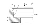
- FIG. 4 is an enlarged cross-sectional view of a case in the case unit of the present embodiment.
- the case 2 of the present embodiment has a step surface portion 9 ⁇ / b> A having a shape different from that of the step surface portion 9 disclosed in the first embodiment.
- step difference surfaces are inclined so that it may go to an outer peripheral side gradually as it leaves
- the first surface portion 8 and the step surface portion 9 ⁇ / b> A formed in the case 2 of the present embodiment are in the placement process of the accommodation object 15 in the placement step disclosed in the first embodiment. It functions as a guide that smoothly guides the object 15 to the placement surface 6. For this reason, according to the case 2 of this embodiment, it is easy to place the accommodation object 15 in the placing process. Further, according to the case 2 of the present embodiment, the frequency of placement failure when placing the accommodation object 15 on the placement surface 6 using a robot can be reduced.
- the circuit board 16 as an example of the object 15 disclosed in the first embodiment allows heat generated by the electronic component 17 mounted on the circuit board 16 to escape to the case 2 via the mounting surface 6.
- the heat radiation pattern may be provided on the peripheral edge portion 16a.
- the arrangement of the electronic components 17 mounted on the circuit board 16 is not particularly limited.
- the placement surface may be, for example, the bottom surface of the case.
- parts other than the peripheral part in the accommodation target are also placed on the placement surface (bottom surface) of the case.
- the present invention can be used as a case in which the object to be stored is resin-sealed, a case unit in which the object to be stored is resin-sealed, and a manufacturing method of this case unit.
Landscapes
- Engineering & Computer Science (AREA)
- Microelectronics & Electronic Packaging (AREA)
- Casings For Electric Apparatus (AREA)
Abstract
L'invention concerne un boîtier (2) qui comprend : une surface de placement (6) sur laquelle est placée une partie de bord périphérique d'un objet à loger (15) ; et une première surface intérieure (7) qui est contiguë à la périphérie extérieure de la surface de placement (6) et qui s'étend dans une direction périphérique de manière à entourer la périphérie extérieure de l'objet à loger (15). La première surface intérieure (7) comprend : une première partie de surface (8) qui est contiguë à la surface de placement (6) et qui s'étend dans la direction périphérique ; une partie de surface d'échelon (9) qui est contiguë à la première partie de surface (8) du côté opposé à la surface de placement (6) avec la première partie de surface (8) intercalée entre elles, la partie de surface d'échelon s'étendant dans la direction périphérique et se déployant à partir de la première partie de surface (8) vers le côté périphérique extérieur ; et une seconde partie de surface (10) qui est contiguë à la partie de surface d'échelon (9) du côté opposé à la première partie de surface (8) avec la partie de surface d'échelon (9) prise en sandwich entre elles, la seconde partie de surface s'étendant dans la direction périphérique et étant située davantage vers le côté périphérique extérieur que la première partie de surface (8). La première partie de surface (8) et la surface de placement (6) présentent une plus faible rugosité de surface que la seconde partie de surface (10).
Priority Applications (2)
| Application Number | Priority Date | Filing Date | Title |
|---|---|---|---|
| PCT/JP2016/055632 WO2017145326A1 (fr) | 2016-02-25 | 2016-02-25 | Boîtier, unité de boîtier, et procédé de fabrication d'unité de boîtier |
| JP2017501730A JP6263670B1 (ja) | 2016-02-25 | 2016-02-25 | ケース、ケースユニット、及びケースユニットの製造方法 |
Applications Claiming Priority (1)
| Application Number | Priority Date | Filing Date | Title |
|---|---|---|---|
| PCT/JP2016/055632 WO2017145326A1 (fr) | 2016-02-25 | 2016-02-25 | Boîtier, unité de boîtier, et procédé de fabrication d'unité de boîtier |
Publications (1)
| Publication Number | Publication Date |
|---|---|
| WO2017145326A1 true WO2017145326A1 (fr) | 2017-08-31 |
Family
ID=59686006
Family Applications (1)
| Application Number | Title | Priority Date | Filing Date |
|---|---|---|---|
| PCT/JP2016/055632 Ceased WO2017145326A1 (fr) | 2016-02-25 | 2016-02-25 | Boîtier, unité de boîtier, et procédé de fabrication d'unité de boîtier |
Country Status (2)
| Country | Link |
|---|---|
| JP (1) | JP6263670B1 (fr) |
| WO (1) | WO2017145326A1 (fr) |
Cited By (1)
| Publication number | Priority date | Publication date | Assignee | Title |
|---|---|---|---|---|
| WO2025004305A1 (fr) * | 2023-06-30 | 2025-01-02 | 三菱電機株式会社 | Moteur électrique, soufflante, climatiseur et procédé de fabrication de moteur électrique |
Citations (4)
| Publication number | Priority date | Publication date | Assignee | Title |
|---|---|---|---|---|
| JPS6181101U (fr) * | 1984-11-01 | 1986-05-29 | ||
| JPH06260777A (ja) * | 1993-03-09 | 1994-09-16 | Toshiba Corp | 電気機器の電子制御装置 |
| JP2004281909A (ja) * | 2003-03-18 | 2004-10-07 | Mitsubishi Electric Corp | 基板取付構造 |
| JP2014029974A (ja) * | 2012-06-26 | 2014-02-13 | Kyocera Corp | 電子部品収納用パッケージ |
Family Cites Families (1)
| Publication number | Priority date | Publication date | Assignee | Title |
|---|---|---|---|---|
| JPH11354586A (ja) * | 1998-06-12 | 1999-12-24 | Nec Kansai Ltd | セラミックパッケ−ジ型電子部品 |
-
2016
- 2016-02-25 JP JP2017501730A patent/JP6263670B1/ja active Active
- 2016-02-25 WO PCT/JP2016/055632 patent/WO2017145326A1/fr not_active Ceased
Patent Citations (4)
| Publication number | Priority date | Publication date | Assignee | Title |
|---|---|---|---|---|
| JPS6181101U (fr) * | 1984-11-01 | 1986-05-29 | ||
| JPH06260777A (ja) * | 1993-03-09 | 1994-09-16 | Toshiba Corp | 電気機器の電子制御装置 |
| JP2004281909A (ja) * | 2003-03-18 | 2004-10-07 | Mitsubishi Electric Corp | 基板取付構造 |
| JP2014029974A (ja) * | 2012-06-26 | 2014-02-13 | Kyocera Corp | 電子部品収納用パッケージ |
Cited By (1)
| Publication number | Priority date | Publication date | Assignee | Title |
|---|---|---|---|---|
| WO2025004305A1 (fr) * | 2023-06-30 | 2025-01-02 | 三菱電機株式会社 | Moteur électrique, soufflante, climatiseur et procédé de fabrication de moteur électrique |
Also Published As
| Publication number | Publication date |
|---|---|
| JPWO2017145326A1 (ja) | 2018-03-01 |
| JP6263670B1 (ja) | 2018-01-24 |
Similar Documents
| Publication | Publication Date | Title |
|---|---|---|
| TW201534194A (zh) | 殼體、應用該殼體的電子裝置及其製作方法 | |
| JP5627618B2 (ja) | 固定治具の製造方法及び固定治具 | |
| JP6263670B1 (ja) | ケース、ケースユニット、及びケースユニットの製造方法 | |
| JP2012209508A (ja) | 電子回路装置 | |
| CN108858445B (zh) | 一种pcb二次冲压成型工艺 | |
| CN109130337B (zh) | 一种蜂窝夹芯板成型方法 | |
| JP6365360B2 (ja) | 電子装置及びその製造方法 | |
| TWI508639B (zh) | 製造電路板的方法和電路板總成 | |
| JP6667105B2 (ja) | 回路基板、回路構成体、及び回路基板の製造方法 | |
| CN113894219A (zh) | 一种用于加工带气膜孔板件的冲压装置及冲压方法 | |
| KR20100072740A (ko) | 금속과 수지의 접합방법 | |
| KR20130077645A (ko) | 카드형 무선 송수신기의 수지 케이스 보정 방법 | |
| EP4654757A2 (fr) | Plaque de renforcement et composant électrique | |
| JP5954912B1 (ja) | 樹脂封止モジュールの製造方法および樹脂封止モジュール | |
| JP5889615B2 (ja) | 樹脂封止モジュールの製造方法および樹脂封止モジュール | |
| US20110292619A1 (en) | Electronic component and method for producing such an electronic component | |
| CN203757620U (zh) | 一种背板、背光模组框架、背光模组及显示装置 | |
| JP2019214127A (ja) | 電子部品モジュールの外装樹脂成形方法 | |
| CN111447316A (zh) | 一种手机壳及其加工方法 | |
| CN105874666A (zh) | 电子电路单元的外壳的成型方法 | |
| CN115224017B (zh) | 半导体器件的半切封装方法及生产方法 | |
| KR101345861B1 (ko) | 연성회로기판용 보강판 가접 지그 | |
| CN105722343B (zh) | 电子装置的机壳的制造方法及应用其形成的机壳 | |
| JP2016004871A (ja) | 電子装置 | |
| JP4783166B2 (ja) | 電気回路装置 |
Legal Events
| Date | Code | Title | Description |
|---|---|---|---|
| ENP | Entry into the national phase |
Ref document number: 2017501730 Country of ref document: JP Kind code of ref document: A |
|
| NENP | Non-entry into the national phase |
Ref country code: DE |
|
| 121 | Ep: the epo has been informed by wipo that ep was designated in this application |
Ref document number: 16891483 Country of ref document: EP Kind code of ref document: A1 |
|
| 122 | Ep: pct application non-entry in european phase |
Ref document number: 16891483 Country of ref document: EP Kind code of ref document: A1 |