WO2017145332A1 - Machine électrique tournante et procédé de fabrication de machine électrique tournante - Google Patents
Machine électrique tournante et procédé de fabrication de machine électrique tournante Download PDFInfo
- Publication number
- WO2017145332A1 WO2017145332A1 PCT/JP2016/055664 JP2016055664W WO2017145332A1 WO 2017145332 A1 WO2017145332 A1 WO 2017145332A1 JP 2016055664 W JP2016055664 W JP 2016055664W WO 2017145332 A1 WO2017145332 A1 WO 2017145332A1
- Authority
- WO
- WIPO (PCT)
- Prior art keywords
- core
- recess
- circumferential direction
- frame
- split
- Prior art date
- Legal status (The legal status is an assumption and is not a legal conclusion. Google has not performed a legal analysis and makes no representation as to the accuracy of the status listed.)
- Ceased
Links
Images


Classifications
-
- H—ELECTRICITY
- H02—GENERATION; CONVERSION OR DISTRIBUTION OF ELECTRIC POWER
- H02K—DYNAMO-ELECTRIC MACHINES
- H02K1/00—Details of the magnetic circuit
- H02K1/06—Details of the magnetic circuit characterised by the shape, form or construction
- H02K1/12—Stationary parts of the magnetic circuit
- H02K1/18—Means for mounting or fastening magnetic stationary parts on to, or to, the stator structures
Definitions
- the disclosed embodiment relates to a rotating electrical machine and a method for manufacturing the rotating electrical machine.
- Patent Document 1 describes a rotating electrical machine in which a stator core is press-fitted into an inner periphery of a frame so that only an outer peripheral portion of a joint portion between split iron cores is pressed into the inner periphery of the frame.
- a gap is formed between the split core and the frame at a portion other than the joint, so that the above-described non-uniform compressive stress and strain generated in the split core can be reduced.
- the joint portion having relatively low rigidity is supported by the frame in the split core, when a large compressive force is applied to the outer peripheral surface of the stator core from the frame, a part of the split core is deformed and the stator. There was a possibility that the cylindrical accuracy of the iron core was broken and the gap between the stator and the rotor was changed.
- An object of the present invention is to provide a rotating electrical machine and a method of manufacturing the rotating electrical machine that are capable of ensuring the cylindrical accuracy of the stator core.
- a frame and a stator core having a plurality of divided cores fixed to the inner peripheral surface of the frame and arranged in the circumferential direction.
- the split cores have contact surfaces in contact with the adjacent split cores at both ends in the circumferential direction, and the stator cores are positioned at positions corresponding to the contact surfaces of the outer peripheral surface.
- a rotating electrical machine provided with one recess is applied.
- a method of manufacturing a rotating electrical machine includes forming a stator core and fixing a frame to the outside of the stator core by shrink fitting.
- a frame a stator core that is fixed to an inner peripheral surface of the frame and includes a plurality of divided cores arranged in a circumferential direction, and the divided cores contact each other.
- a rotating electrical machine having means for forming a gap between the outer peripheral surface of the stator core and the inner peripheral surface of the frame is applied at a position corresponding to the contact surface.
- the present invention even when a large compressive force is applied from the frame to the outer periphery of the stator core of the rotating electrical machine, it is possible to suppress the occurrence of uneven compressive stress or strain in the split core, and the stator core Cylindrical accuracy can be ensured.
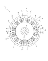
- FIG. 2 is a cross-sectional view taken along the line II-II in FIG. 1 showing an example of the overall configuration of the rotating electrical machine according to an embodiment.
- It is explanatory drawing which extracts and represents a part of stator iron core which the division
- FIGS. 1 and 2 are axial sectional views showing an example of the overall configuration of the rotating electrical machine 1
- FIG. 2 is a transverse sectional view taken along the line II-II of FIG.
- the rotating electrical machine 1 includes a stator 2, a rotor 3, a frame 4, a load side bracket 11, and an anti-load side bracket 13.
- the rotating electrical machine 1 is used as a motor or a generator.
- the rotor 3 includes a shaft 10, a rotor core 15 provided on the outer periphery of the shaft 10, and a plurality of permanent magnets (not shown) disposed on the rotor core 15.
- the rotor core 15 is configured by laminating a plurality of electromagnetic steel plates in the axial direction, and is disposed so as to face the stator 2 in the radial direction.
- the load side bracket 11 is fixed to the load side (right side in FIG. 1) of the frame 4, and the anti-load side bracket 13 is fixed to the anti-load side (left side in FIG. 1) of the frame 4.
- the shaft 10 is rotatably supported around the rotation axis AX by a load side bearing 12 provided on the load side bracket 11 and an antiload side bearing 14 provided on the antiload side bracket 13.
- the “load side” refers to the direction in which a load is attached to the rotating electrical machine 1, that is, the direction in which the shaft 10 protrudes (right side in FIG. 1) in this example. It points in the opposite direction to the load side (left side in FIG. 1).
- axial direction refers to the direction along the rotational axis AX of the shaft 10 (rotor 3)
- circumferential direction refers to the circumferential direction around the rotational axis AX
- diameter refers to a radial direction around the rotation axis AX.
- the stator 2 is disposed on the inner peripheral side of the frame 4 so as to face the rotor 3 in the radial direction.
- the stator 2 includes a stator core 5 provided on the inner peripheral surface of the frame 4, a bobbin 6 attached to the stator core 5, a winding 7 wound around the bobbin 6, and a resin portion 35.
- the bobbin 6 is made of an insulating material in order to electrically insulate the stator core 5 and the winding 7 from each other.
- the bobbin 6 may be a sheet-like insulator.
- the stator core 5 is configured by combining a plurality (12 in the illustrated example) of divided cores 20 (also referred to as core pieces) in the circumferential direction.
- Each divided iron core 20 is configured by laminating a plurality of electromagnetic steel plates formed in a predetermined shape by, for example, press punching in the axial direction.
- the split iron core 20 includes a substantially arc-shaped yoke portion 21 and a teeth portion 22 provided integrally with the yoke portion 21.
- the teeth part 22 is provided with a main body part 22a provided so as to protrude radially inward from the yoke part 21, and a widened part 22b provided at the front end on the inner peripheral side of the main body part 22a and having an increased circumferential width. And have.
- the tips of adjacent widened portions 22b are separated in the circumferential direction, but may be in contact with each other.
- Each of the divided cores 20 is connected to the teeth portion 22 in the circumferential direction after the bobbin 6 and the winding 7 are mounted, and the stator core 5 is formed. Then, after the stator core 5 is fixed to the inner peripheral surface of the frame 4 by press fitting or shrink fitting, it is molded with resin. As a result, as shown in FIG. 1, the stator core 5 (divided core 20), the bobbin 6, and the winding 7 are integrally fixed by a resin portion 35 made of resin.
- the windings 7 attached to the respective tooth portions 22 are accommodated in the slot portions 19 between the teeth portions 22 adjacent in the circumferential direction, and the opposite sides of the winding layers of the windings 7.
- the parts are arranged with a gap 19a therebetween. Resin is press-fitted into the gap 19a at the time of molding, and the resin portion 35 is filled. In addition, resin is press-fitted into the core groove 18 and the first recess 30 (described later) of each divided iron core 20 at the time of molding, and the resin portion 35 is filled.
- substantially annular projecting portions 35a and 35b are formed at the load side end portion and the anti-load side end portion of the resin portion 35, respectively. These protrusions 35a and 35b are inlay-fitted to the load side bracket 11 and the anti-load side bracket 13, respectively.
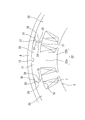
- FIG. 3 is an explanatory view showing a part of the rotor core in which the divided cores are arranged in the circumferential direction.
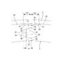
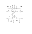
- FIG. 4 is an explanatory view showing the vicinity of the contact surface of the divided cores adjacent in the circumferential direction. 3 and 4, the bobbin 6 and the resin portion 35 are not shown.
- the split iron core 20 has an arcuate yoke portion 21 and a teeth portion 22.
- the teeth part 22 has a main body part 22a and a widened part 22b.
- a core groove 18 is formed on the outer peripheral surface of the split iron core 20 along the axial direction at the center in the circumferential direction.
- the core groove 18 is provided to reduce stress concentration on the slot portion 19 when the stator core 5 is attached to the inner peripheral surface of the frame 4 by shrink fitting or the like.
- the cross-sectional shape of the core groove 18 is, for example, a shape (isosceles trapezoidal shape, so-called dovetail shape) whose width in the circumferential direction increases toward the inside in the radial direction.
- each divided core 20 has contact surfaces 24 and 26 that come into contact with the adjacent divided core 20 at both ends in the circumferential direction. That is, the divided iron cores 20 adjacent in the circumferential direction are connected with the contact surfaces 24 and 26 in contact with each other.
- the split iron core 20 has a first protrusion 23 on the contact surface 24 on one end (left side in FIG. 3) in the circumferential direction, and the contact surface on the other end (right side in FIG. 3) in the circumferential direction.
- 26 has a second recess 25.
- the second recess 25 accommodates the first protrusion 23 of the adjacent split iron core 20.
- the first protrusion 23 has a taper shape (substantially trapezoidal shape) in which the cross-sectional shape orthogonal to the axial direction decreases in the radial direction toward the tip on one side in the circumferential direction.
- the second recess 25 has the same shape as the first protrusion 23, and the cross-sectional shape orthogonal to the axial direction is such that the radial opening width decreases toward the tip on one side in the circumferential direction (substantially trapezoidal). Groove shape). As shown in FIG. 4, the first projecting portion 23 and the tapered portion of the second recess 25 are surely in contact between the tip of the first projecting portion 23 and the bottom of the second recess 25. A minute gap S is provided.
- the split iron core 20 has two second protrusions 27 on both sides in the radial direction of the second recess 25.
- the second projecting portion 27 has a cross-sectional shape orthogonal to the axial direction such that the radial width of the tip portion is smaller than the radial width of the root portion.
- 1st recessed part 30 is formed in the outer peripheral surface of the stator core 5 in the position corresponding to the contact surfaces 24 and 26.
- the first recess 30 has a predetermined width in the circumferential direction across the outer peripheral surface of the split core 20 having the first protrusion 23 and the outer peripheral surface of the split core 20 having the second recess 25. It is formed as follows.
- the circumferential width La2 of the first recess 30 in the divided iron core 20 having the first protrusion 23 is not particularly limited, but in this example, the width La1 is used. It is almost the same.
- the width La1 and the width La2 may be different.
- the second protrusion on the radially outer side of the second recess 25 is formed by the taper shape of the first protrusion 23.
- the portion 27 is deformed by being pushed outward in the radial direction, the second protrusion 27 is allowed to deform toward the frame 4.
- the compressive force from the left and right divided iron cores 20 on the contact surfaces 24 and 26 can be relaxed, and the deformed second protrusion 27 can be prevented from receiving a reaction force from the frame 4.
- the depth of the first recess 30 in the radial direction is set to a depth that allows the deformation of the second protrusion 27.
- the cross-sectional shape of the corner R1 located between the first recess 30 and the outer peripheral surface of the stator core 5 is the compressive force from the frame 4.
- the shape is chamfered in an arc shape so that stress concentration does not occur in the corner portion R1.
- the cross-sectional shape of the corner portion R2 located on both sides in the circumferential direction of the bottom portion of the first recess 30 is similarly a chamfered shape in an arc shape.
- the cross-sectional shape of each corner and each corner (indicated by reference numerals R3 to R8 in FIG. 4) of the contact surfaces 24 and 26 of the split iron core 20 does not cause stress concentration due to the compressive force on the contact surfaces 24 and 26. In this way, each of the shapes is chamfered in an arc shape.
- the rotating electrical machine 1 of this embodiment is assembled as follows.
- Each of the divided cores 20 is disposed so as to be connected in the circumferential direction after the bobbin 6 and the winding 7 are mounted on the tooth portion 22, and corresponds to the contact surfaces 24 and 26 where the divided cores 20 on the outer peripheral surface come into contact with each other.
- the stator core 5 in which the first concave portion 30 is provided is formed at the position to be.
- the stator core 5 is fixed inside the frame 4 by press fitting or shrink fitting. Thereafter, the stator core 5 and the plurality of windings 7 and the like attached to the stator core 5 are integrated with resin to form the resin portion 35. In this way, the stator 2 is assembled.
- the load side bracket 11 on which the shaft 10 is installed is fixed to the load side of the frame 4 while the shaft 10 and the rotor 3 are inserted inside the stator 2.
- the protruding portion 35 a of the resin portion 35 is fitted and positioned in the concave portion of the inner peripheral surface of the load side bracket 11.
- the anti-load side bracket 13 is fixed to the anti-load side of the frame 4 while pressing the shaft 10 into the anti-load side bearing 14.
- the protruding portion 35 b of the resin portion 35 is fitted and positioned in the concave portion on the inner peripheral surface of the anti-load side bracket 13.
- the order in which the load side bracket 11 and the anti-load side bracket 13 are assembled may be opposite to the above.
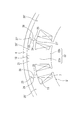
- the stator core 5 ′ of Comparative Example 1 shown in FIG. 5 is configured by connecting a plurality of divided cores 20 ′ in the circumferential direction.
- the first recess 30 is not provided on the outer peripheral surface of the stator core 5 ′ at a position corresponding to the contact surfaces 24 and 26.
- Other configurations of the stator core 5 ′ and the split core 20 ′ are the same as those of the rotor core 5 and the split core 20 described above.
- the first recess 30 is not provided at a position corresponding to the contact surfaces 24, 26 on the outer peripheral surface, so that the outer peripheral surface of the stator core 5 ′ is the contact surface 24, 26 also contacts the inner peripheral surface of the frame 4.
- the problems of the comparative example 1 and the comparative example 2 can be solved, and the occurrence of non-uniform compressive stress, strain, and the like in the split core 20 can be suppressed. That is, in the rotating electrical machine 1 of the present embodiment, the first recess 30 is formed at a position corresponding to the contact surfaces 24 and 26 on the outer peripheral surface of the stator core 5. As a result, a gap due to the first recess 30 can be formed between the stator core 5 and the frame 4 in the vicinity of the contact surfaces 24 and 26 of the split core 20.
- the contact area between the inner peripheral surface of the frame 4 and the outer peripheral surface of the stator core 5 can be reduced by the first recess 30 as compared with the first comparative example, the inner diameter and thickness variation of the frame 4 and the divided cores are reduced. The influence of the variation of the outer diameter of 20 can be reduced. Therefore, it is possible to suppress the generation of uneven compressive stress or strain in the split core 20.
- the contact area of the inner peripheral surface of the frame 4 and the outer peripheral surface of the stator core 5 can be increased as compared with the configuration in which only the outer peripheral portion of the contact surface is in contact with the frame 4 as in the comparative example 2, the fixed area The heat conduction between the child 2 and the frame 4 can be improved.
- the split iron core 20 has the first protrusion 23 on the contact surface 24 at one end in the circumferential direction, and is adjacent to the contact surface 26 at the other end in the circumferential direction.
- the first protrusion 23 has a second recess 25 in which the first protrusion 23 of the split core 20 is accommodated.
- the first protrusion 23 has a cross-sectional shape orthogonal to the axial direction and a radial width directed toward the tip of the one side. The taper shape becomes smaller. Thereby, there exists the following effect.
- the plurality of divided cores 20 are connected in the circumferential direction in a state where each first protrusion 23 is accommodated in the second recess 25 of the adjacent divided core 20.
- the plurality of divided cores 20 are arranged so as to be connected in the circumferential direction, and the first recess 30 is formed at a position corresponding to the contact surfaces 24 and 26 on the outer circumferential surface.
- the formed stator core 5 is formed.
- the concave and convex fitting between the first projecting portion 23 and the second concave portion 25 facilitates positioning of each divided iron core 20 and makes it easy to maintain the cylindrical shape of the stator iron core 5.
- the taper shape of the first protrusion 23 is the second.
- the compressive force of the contact surfaces 24 and 26 can be relaxed. Thereby, it is possible to suppress the occurrence of non-uniform compressive stress, strain, and the like in the split core 20 and to ensure the cylindrical accuracy of the stator core 5.
- the split iron core 20 has two second protrusions 27 arranged on both sides in the radial direction of the second recess 25 on the contact surface 26 at the other end in the circumferential direction.
- the second projecting portion 27 has a cross-sectional shape orthogonal to the axial direction such that the radial width of the tip portion is smaller than the radial width of the root portion.
- the plurality of divided iron cores 20 are accommodated in the second recesses 25 formed between the two second protrusions 27 of the adjacent divided iron cores 20 with the first protrusions 23 being adjacent to each other.
- the cross-sectional shape orthogonal to the axial direction of the 2nd projection part 27 is a shape whose radial width of a front-end
- tip part is smaller than the radial width of a root part.
- the cross-sectional shape of the second recess 25 becomes a shape in which the opening width in the radial direction becomes smaller toward the bottom, and can be a shape that fits with the first protrusion 23 having a tapered shape.
- the first recess 30 has a predetermined circumferential direction across the outer peripheral surface of the split core 20 having the first protrusion 23 and the outer peripheral surface of the split core 20 having the second recess 25.
- the circumferential width La1 of the first recess 30 in the split iron core 20 having the second recess 25 is larger than the circumferential depth Lb of the second recess 25.
- the first recess 30 has a shape in which the corner R1 located between at least the outer peripheral surface of the stator core 5 is chamfered.
- the split iron core 20 has the 1st projection part 23 in the contact surface 24 of the edge part of the one side in the circumferential direction, and has the 2nd recessed part 25 in the contact surface 26 of the edge part of the other side in the circumferential direction.
- the contact surface may be a flat surface having neither a protrusion nor a recess.
- the split core 20 ⁇ / b> A of this modification has a flat contact surface 34 in the radial direction at the end portion on one side (left side in FIG. 6) in the circumferential direction, and the other side in the circumferential direction (FIG. 6 has a contact surface 36 that is flat in the radial direction and in contact with the contact surface 34.
- the plurality of divided iron cores 20A are connected in the circumferential direction with the contact surfaces 34 and 36 in contact with each other.
- a first recess 30 is formed in the stator core 5A at a position corresponding to the contact surfaces 34 and 36 on the outer peripheral surface.
- Other configurations of this modification are the same as those of the above embodiment.
- the split iron core 20 has the first protrusion 23 having a tapered shape whose cross-sectional shape decreases toward the tip on the contact surface 24, and the opening width in the radial direction of the cross-sectional shape on the contact surface 26 is at the tip.
- the first protrusion and the second recess may have a substantially rectangular cross-sectional shape perpendicular to the axial direction.
- An example of the configuration of the contact surface portion of the split iron core in this modification is shown in FIG.
- the split core 20B of the present modification has a cross-sectional shape orthogonal to the axial direction directed toward one side in the circumferential direction on the contact surface 44 on one end (left side in FIG. 7) in the circumferential direction.
- the first protrusion 43 has a substantially rectangular shape that protrudes.
- the split iron core 20B has a second recess 45 for accommodating the first protrusion 43 on the contact surface 46 at the other end (right side in FIG. 7) in the circumferential direction.
- the second recess 45 has a substantially rectangular groove shape in which a cross-sectional shape orthogonal to the axial direction is recessed toward one side in the circumferential direction.
- the split iron core 20 ⁇ / b> B has two second protrusions 47 disposed on both sides in the radial direction of the second recess 45 on the contact surface 46.
- the second protrusion 47 has a substantially rectangular cross-sectional shape orthogonal to the axial direction.
- a first recess 30 is formed in the stator core 5B at a position corresponding to the contact surfaces 44 and 46 on the outer peripheral surface. Other configurations of this modification are the same as those of the above embodiment.
Landscapes
- Engineering & Computer Science (AREA)
- Power Engineering (AREA)
- Iron Core Of Rotating Electric Machines (AREA)
Abstract
Le problème décrit par la présente invention est de supprimer la contrainte de compression non uniforme, la tension, et similaires dans des noyaux divisés et d'assurer une tolérance de cylindricité précise d'un noyau de stator d'une machine électrique tournante, même lorsqu'une grande force de compression agit depuis un cadre sur la circonférence extérieure du noyau de stator. La solution selon l'invention porte sur une machine électrique tournante 1 ayant un cadre 4, et un noyau de stator 5 équipé de multiples noyaux divisés 20 fixés à la surface circonférentielle intérieure du cadre 4 et disposés dans la direction circonférentielle. Les noyaux divisés 20 présentent, au niveau des deux extrémités dans la direction circonférentielle, des surfaces de contact 24 et 26 en contact avec les noyaux divisés 20 adjacents. Des premières parties concaves 30 sont disposées sur la surface circonférentielle extérieure du noyau de stator 5 à des emplacements correspondant aux surfaces de contact 24 et 26.
Priority Applications (3)
| Application Number | Priority Date | Filing Date | Title |
|---|---|---|---|
| PCT/JP2016/055664 WO2017145332A1 (fr) | 2016-02-25 | 2016-02-25 | Machine électrique tournante et procédé de fabrication de machine électrique tournante |
| CN201680082491.6A CN108702042B (zh) | 2016-02-25 | 2016-02-25 | 旋转电机和旋转电机的制造方法 |
| JP2018501504A JP6621058B2 (ja) | 2016-02-25 | 2016-02-25 | 回転電機及び回転電機の製造方法 |
Applications Claiming Priority (1)
| Application Number | Priority Date | Filing Date | Title |
|---|---|---|---|
| PCT/JP2016/055664 WO2017145332A1 (fr) | 2016-02-25 | 2016-02-25 | Machine électrique tournante et procédé de fabrication de machine électrique tournante |
Publications (1)
| Publication Number | Publication Date |
|---|---|
| WO2017145332A1 true WO2017145332A1 (fr) | 2017-08-31 |
Family
ID=59684900
Family Applications (1)
| Application Number | Title | Priority Date | Filing Date |
|---|---|---|---|
| PCT/JP2016/055664 Ceased WO2017145332A1 (fr) | 2016-02-25 | 2016-02-25 | Machine électrique tournante et procédé de fabrication de machine électrique tournante |
Country Status (3)
| Country | Link |
|---|---|
| JP (1) | JP6621058B2 (fr) |
| CN (1) | CN108702042B (fr) |
| WO (1) | WO2017145332A1 (fr) |
Cited By (5)
| Publication number | Priority date | Publication date | Assignee | Title |
|---|---|---|---|---|
| WO2019044612A1 (fr) * | 2017-09-04 | 2019-03-07 | 株式会社ミツバ | Moteur électrique |
| KR102031852B1 (ko) * | 2018-05-08 | 2019-10-14 | 엘지전자 주식회사 | 전동식 압축기 |
| JP2021065042A (ja) * | 2019-10-15 | 2021-04-22 | 株式会社ミツバ | ブラシレスモータ及びステータ製造方法 |
| JP2023023370A (ja) * | 2021-08-05 | 2023-02-16 | 日本製鉄株式会社 | 分割型固定子および回転電機 |
| WO2023224014A1 (fr) * | 2022-05-16 | 2023-11-23 | 株式会社デンソー | Stator et machine électrique tournante |
Families Citing this family (1)
| Publication number | Priority date | Publication date | Assignee | Title |
|---|---|---|---|---|
| DE102020204576A1 (de) * | 2020-04-09 | 2021-10-14 | Robert Bosch Gesellschaft mit beschränkter Haftung | Lamellenpaket für eine elektrische Maschine, sowie eine elektrische Maschine aufweisend ein Lamellenpaket, und Verfahren zum Herstellen eines Statorgrundkörpers |
Citations (3)
| Publication number | Priority date | Publication date | Assignee | Title |
|---|---|---|---|---|
| JP2002186205A (ja) * | 2000-12-14 | 2002-06-28 | Nissan Motor Co Ltd | 回転電機 |
| JP2010148329A (ja) * | 2008-12-22 | 2010-07-01 | Mazda Motor Corp | 回転電機のステータコア構造 |
| JP2011135634A (ja) * | 2009-12-22 | 2011-07-07 | Toyota Motor Corp | ステータおよびこのステータを備えるモータ |
Family Cites Families (3)
| Publication number | Priority date | Publication date | Assignee | Title |
|---|---|---|---|---|
| JP2007028799A (ja) * | 2005-07-15 | 2007-02-01 | Asmo Co Ltd | コアの製造方法 |
| WO2011125199A1 (fr) * | 2010-04-08 | 2011-10-13 | 三菱電機株式会社 | Noyau de fer feuilleté de machine électrique tournante |
| JP2013042620A (ja) * | 2011-08-18 | 2013-02-28 | Hitachi Automotive Systems Ltd | 回転電機 |
-
2016
- 2016-02-25 WO PCT/JP2016/055664 patent/WO2017145332A1/fr not_active Ceased
- 2016-02-25 JP JP2018501504A patent/JP6621058B2/ja active Active
- 2016-02-25 CN CN201680082491.6A patent/CN108702042B/zh active Active
Patent Citations (3)
| Publication number | Priority date | Publication date | Assignee | Title |
|---|---|---|---|---|
| JP2002186205A (ja) * | 2000-12-14 | 2002-06-28 | Nissan Motor Co Ltd | 回転電機 |
| JP2010148329A (ja) * | 2008-12-22 | 2010-07-01 | Mazda Motor Corp | 回転電機のステータコア構造 |
| JP2011135634A (ja) * | 2009-12-22 | 2011-07-07 | Toyota Motor Corp | ステータおよびこのステータを備えるモータ |
Cited By (7)
| Publication number | Priority date | Publication date | Assignee | Title |
|---|---|---|---|---|
| WO2019044612A1 (fr) * | 2017-09-04 | 2019-03-07 | 株式会社ミツバ | Moteur électrique |
| KR102031852B1 (ko) * | 2018-05-08 | 2019-10-14 | 엘지전자 주식회사 | 전동식 압축기 |
| JP2021065042A (ja) * | 2019-10-15 | 2021-04-22 | 株式会社ミツバ | ブラシレスモータ及びステータ製造方法 |
| JP7254675B2 (ja) | 2019-10-15 | 2023-04-10 | 株式会社ミツバ | ブラシレスモータ及びステータ製造方法 |
| JP2023023370A (ja) * | 2021-08-05 | 2023-02-16 | 日本製鉄株式会社 | 分割型固定子および回転電機 |
| JP7799162B2 (ja) | 2021-08-05 | 2026-01-15 | 日本製鉄株式会社 | 分割型固定子および回転電機 |
| WO2023224014A1 (fr) * | 2022-05-16 | 2023-11-23 | 株式会社デンソー | Stator et machine électrique tournante |
Also Published As
| Publication number | Publication date |
|---|---|
| JPWO2017145332A1 (ja) | 2018-10-11 |
| CN108702042B (zh) | 2020-10-23 |
| JP6621058B2 (ja) | 2019-12-18 |
| CN108702042A (zh) | 2018-10-23 |
Similar Documents
| Publication | Publication Date | Title |
|---|---|---|
| JP6621058B2 (ja) | 回転電機及び回転電機の製造方法 | |
| JP5489698B2 (ja) | インシュレータ、回転電機および回転電機の製造方法 | |
| US9735636B2 (en) | Rotor and dynamo-electric machine having the same | |
| US10069387B2 (en) | Fixing method and fixing structure for fixing a coil insulator, stator using the same and rotating electrical machine using the same | |
| CN104380577B (zh) | 旋转电机 | |
| CN112640259A (zh) | 马达及马达的制造方法 | |
| CN102957242B (zh) | 旋转电机的转子、旋转电机以及转子的端面部件 | |
| WO2018110300A1 (fr) | Noyau de stator de machine électrique tournante et son procédé de fabrication | |
| JPWO2017141361A1 (ja) | 回転電機及び回転電機の製造方法 | |
| JP5414903B2 (ja) | 回転電機 | |
| JP2016123240A (ja) | 電動機用ロータ及びその製造方法 | |
| WO2015050010A1 (fr) | Noyau de rotor, rotor et machine électrique rotative | |
| JP6593731B2 (ja) | 回転電機及び回転電機の製造方法 | |
| JP2012065510A (ja) | ステータ | |
| KR20250120236A (ko) | 모터 | |
| JP7211883B2 (ja) | ステータおよびモータ | |
| WO2017158847A1 (fr) | Machine électrique tournante et procédé de fabrication de la machine électrique tournante | |
| CN112236925B (zh) | 旋转电机的定子以及旋转电机 | |
| JP2014003881A (ja) | 回転電機のステータ | |
| JP6297802B2 (ja) | レゾルバの取り付け構造 | |
| JP7218854B2 (ja) | 回転電機、インシュレータ、およびそのアセンブリ方法 | |
| WO2020080548A1 (fr) | Moteur | |
| JP2009106004A (ja) | 回転電機 | |
| JP2012044789A (ja) | 回転電機およびその製造方法 | |
| JP7561719B2 (ja) | ステータ、及び、回転電機 |
Legal Events
| Date | Code | Title | Description |
|---|---|---|---|
| ENP | Entry into the national phase |
Ref document number: 2018501504 Country of ref document: JP Kind code of ref document: A |
|
| NENP | Non-entry into the national phase |
Ref country code: DE |
|
| 121 | Ep: the epo has been informed by wipo that ep was designated in this application |
Ref document number: 16891489 Country of ref document: EP Kind code of ref document: A1 |
|
| 122 | Ep: pct application non-entry in european phase |
Ref document number: 16891489 Country of ref document: EP Kind code of ref document: A1 |