WO2017145333A1 - Machine électrique tournante de type à entrefer axial - Google Patents
Machine électrique tournante de type à entrefer axial Download PDFInfo
- Publication number
- WO2017145333A1 WO2017145333A1 PCT/JP2016/055676 JP2016055676W WO2017145333A1 WO 2017145333 A1 WO2017145333 A1 WO 2017145333A1 JP 2016055676 W JP2016055676 W JP 2016055676W WO 2017145333 A1 WO2017145333 A1 WO 2017145333A1
- Authority
- WO
- WIPO (PCT)
- Prior art keywords
- gap type
- axial gap
- type rotating
- electrical machine
- rotating electrical
- Prior art date
- Legal status (The legal status is an assumption and is not a legal conclusion. Google has not performed a legal analysis and makes no representation as to the accuracy of the status listed.)
- Ceased
Links
Images





Classifications
-
- H—ELECTRICITY
- H02—GENERATION; CONVERSION OR DISTRIBUTION OF ELECTRIC POWER
- H02K—DYNAMO-ELECTRIC MACHINES
- H02K16/00—Machines with more than one rotor or stator
- H02K16/02—Machines with one stator and two or more rotors
-
- F—MECHANICAL ENGINEERING; LIGHTING; HEATING; WEAPONS; BLASTING
- F04—POSITIVE - DISPLACEMENT MACHINES FOR LIQUIDS; PUMPS FOR LIQUIDS OR ELASTIC FLUIDS
- F04D—NON-POSITIVE-DISPLACEMENT PUMPS
- F04D13/00—Pumping installations or systems
- F04D13/02—Units comprising pumps and their driving means
- F04D13/06—Units comprising pumps and their driving means the pump being electrically driven
- F04D13/0606—Canned motor pumps
-
- F—MECHANICAL ENGINEERING; LIGHTING; HEATING; WEAPONS; BLASTING
- F04—POSITIVE - DISPLACEMENT MACHINES FOR LIQUIDS; PUMPS FOR LIQUIDS OR ELASTIC FLUIDS
- F04D—NON-POSITIVE-DISPLACEMENT PUMPS
- F04D13/00—Pumping installations or systems
- F04D13/02—Units comprising pumps and their driving means
- F04D13/06—Units comprising pumps and their driving means the pump being electrically driven
- F04D13/0666—Units comprising pumps and their driving means the pump being electrically driven the motor being of the plane gap type
-
- F—MECHANICAL ENGINEERING; LIGHTING; HEATING; WEAPONS; BLASTING
- F04—POSITIVE - DISPLACEMENT MACHINES FOR LIQUIDS; PUMPS FOR LIQUIDS OR ELASTIC FLUIDS
- F04D—NON-POSITIVE-DISPLACEMENT PUMPS
- F04D29/00—Details, component parts, or accessories
- F04D29/58—Cooling; Heating; Diminishing heat transfer
- F04D29/5806—Cooling the drive system
-
- F—MECHANICAL ENGINEERING; LIGHTING; HEATING; WEAPONS; BLASTING
- F04—POSITIVE - DISPLACEMENT MACHINES FOR LIQUIDS; PUMPS FOR LIQUIDS OR ELASTIC FLUIDS
- F04D—NON-POSITIVE-DISPLACEMENT PUMPS
- F04D3/00—Axial-flow pumps
-
- F—MECHANICAL ENGINEERING; LIGHTING; HEATING; WEAPONS; BLASTING
- F28—HEAT EXCHANGE IN GENERAL
- F28D—HEAT-EXCHANGE APPARATUS, NOT PROVIDED FOR IN ANOTHER SUBCLASS, IN WHICH THE HEAT-EXCHANGE MEDIA DO NOT COME INTO DIRECT CONTACT
- F28D15/00—Heat-exchange apparatus with the intermediate heat-transfer medium in closed tubes passing into or through the conduit walls ; Heat-exchange apparatus employing intermediate heat-transfer medium or bodies
- F28D15/02—Heat-exchange apparatus with the intermediate heat-transfer medium in closed tubes passing into or through the conduit walls ; Heat-exchange apparatus employing intermediate heat-transfer medium or bodies in which the medium condenses and evaporates, e.g. heat pipes
-
- F—MECHANICAL ENGINEERING; LIGHTING; HEATING; WEAPONS; BLASTING
- F28—HEAT EXCHANGE IN GENERAL
- F28D—HEAT-EXCHANGE APPARATUS, NOT PROVIDED FOR IN ANOTHER SUBCLASS, IN WHICH THE HEAT-EXCHANGE MEDIA DO NOT COME INTO DIRECT CONTACT
- F28D15/00—Heat-exchange apparatus with the intermediate heat-transfer medium in closed tubes passing into or through the conduit walls ; Heat-exchange apparatus employing intermediate heat-transfer medium or bodies
- F28D15/02—Heat-exchange apparatus with the intermediate heat-transfer medium in closed tubes passing into or through the conduit walls ; Heat-exchange apparatus employing intermediate heat-transfer medium or bodies in which the medium condenses and evaporates, e.g. heat pipes
- F28D15/0233—Heat-exchange apparatus with the intermediate heat-transfer medium in closed tubes passing into or through the conduit walls ; Heat-exchange apparatus employing intermediate heat-transfer medium or bodies in which the medium condenses and evaporates, e.g. heat pipes the conduits having a particular shape, e.g. non-circular cross-section, annular
-
- F—MECHANICAL ENGINEERING; LIGHTING; HEATING; WEAPONS; BLASTING
- F28—HEAT EXCHANGE IN GENERAL
- F28D—HEAT-EXCHANGE APPARATUS, NOT PROVIDED FOR IN ANOTHER SUBCLASS, IN WHICH THE HEAT-EXCHANGE MEDIA DO NOT COME INTO DIRECT CONTACT
- F28D15/00—Heat-exchange apparatus with the intermediate heat-transfer medium in closed tubes passing into or through the conduit walls ; Heat-exchange apparatus employing intermediate heat-transfer medium or bodies
- F28D15/02—Heat-exchange apparatus with the intermediate heat-transfer medium in closed tubes passing into or through the conduit walls ; Heat-exchange apparatus employing intermediate heat-transfer medium or bodies in which the medium condenses and evaporates, e.g. heat pipes
- F28D15/04—Heat-exchange apparatus with the intermediate heat-transfer medium in closed tubes passing into or through the conduit walls ; Heat-exchange apparatus employing intermediate heat-transfer medium or bodies in which the medium condenses and evaporates, e.g. heat pipes with tubes having a capillary structure
-
- H—ELECTRICITY
- H02—GENERATION; CONVERSION OR DISTRIBUTION OF ELECTRIC POWER
- H02K—DYNAMO-ELECTRIC MACHINES
- H02K1/00—Details of the magnetic circuit
- H02K1/06—Details of the magnetic circuit characterised by the shape, form or construction
- H02K1/12—Stationary parts of the magnetic circuit
- H02K1/14—Stator cores with salient poles
- H02K1/146—Stator cores with salient poles consisting of a generally annular yoke with salient poles
-
- H—ELECTRICITY
- H02—GENERATION; CONVERSION OR DISTRIBUTION OF ELECTRIC POWER
- H02K—DYNAMO-ELECTRIC MACHINES
- H02K11/00—Structural association of dynamo-electric machines with electric components or with devices for shielding, monitoring or protection
- H02K11/30—Structural association with control circuits or drive circuits
- H02K11/33—Drive circuits, e.g. power electronics
-
- H—ELECTRICITY
- H02—GENERATION; CONVERSION OR DISTRIBUTION OF ELECTRIC POWER
- H02K—DYNAMO-ELECTRIC MACHINES
- H02K11/00—Structural association of dynamo-electric machines with electric components or with devices for shielding, monitoring or protection
- H02K11/40—Structural association with grounding devices
-
- H—ELECTRICITY
- H02—GENERATION; CONVERSION OR DISTRIBUTION OF ELECTRIC POWER
- H02K—DYNAMO-ELECTRIC MACHINES
- H02K21/00—Synchronous motors having permanent magnets; Synchronous generators having permanent magnets
- H02K21/12—Synchronous motors having permanent magnets; Synchronous generators having permanent magnets with stationary armatures and rotating magnets
- H02K21/24—Synchronous motors having permanent magnets; Synchronous generators having permanent magnets with stationary armatures and rotating magnets with magnets axially facing the armatures, e.g. hub-type cycle dynamos
-
- H—ELECTRICITY
- H02—GENERATION; CONVERSION OR DISTRIBUTION OF ELECTRIC POWER
- H02K—DYNAMO-ELECTRIC MACHINES
- H02K5/00—Casings; Enclosures; Supports
- H02K5/04—Casings or enclosures characterised by the shape, form or construction thereof
- H02K5/18—Casings or enclosures characterised by the shape, form or construction thereof with ribs or fins for improving heat transfer
-
- H—ELECTRICITY
- H02—GENERATION; CONVERSION OR DISTRIBUTION OF ELECTRIC POWER
- H02K—DYNAMO-ELECTRIC MACHINES
- H02K9/00—Arrangements for cooling or ventilating
- H02K9/02—Arrangements for cooling or ventilating by ambient air flowing through the machine
- H02K9/04—Arrangements for cooling or ventilating by ambient air flowing through the machine having means for generating a flow of cooling medium
-
- H—ELECTRICITY
- H02—GENERATION; CONVERSION OR DISTRIBUTION OF ELECTRIC POWER
- H02K—DYNAMO-ELECTRIC MACHINES
- H02K9/00—Arrangements for cooling or ventilating
- H02K9/14—Arrangements for cooling or ventilating wherein gaseous cooling medium circulates between the machine casing and a surrounding mantle
-
- H—ELECTRICITY
- H02—GENERATION; CONVERSION OR DISTRIBUTION OF ELECTRIC POWER
- H02K—DYNAMO-ELECTRIC MACHINES
- H02K9/00—Arrangements for cooling or ventilating
- H02K9/22—Arrangements for cooling or ventilating by solid heat conducting material embedded in, or arranged in contact with, the stator or rotor, e.g. heat bridges
- H02K9/225—Heat pipes
-
- F—MECHANICAL ENGINEERING; LIGHTING; HEATING; WEAPONS; BLASTING
- F28—HEAT EXCHANGE IN GENERAL
- F28D—HEAT-EXCHANGE APPARATUS, NOT PROVIDED FOR IN ANOTHER SUBCLASS, IN WHICH THE HEAT-EXCHANGE MEDIA DO NOT COME INTO DIRECT CONTACT
- F28D21/00—Heat-exchange apparatus not covered by any of the groups F28D1/00 - F28D20/00
- F28D2021/0019—Other heat exchangers for particular applications; Heat exchange systems not otherwise provided for
- F28D2021/0028—Other heat exchangers for particular applications; Heat exchange systems not otherwise provided for for cooling heat generating elements, e.g. for cooling electronic components or electric devices
-
- F—MECHANICAL ENGINEERING; LIGHTING; HEATING; WEAPONS; BLASTING
- F28—HEAT EXCHANGE IN GENERAL
- F28D—HEAT-EXCHANGE APPARATUS, NOT PROVIDED FOR IN ANOTHER SUBCLASS, IN WHICH THE HEAT-EXCHANGE MEDIA DO NOT COME INTO DIRECT CONTACT
- F28D21/00—Heat-exchange apparatus not covered by any of the groups F28D1/00 - F28D20/00
- F28D2021/0019—Other heat exchangers for particular applications; Heat exchange systems not otherwise provided for
- F28D2021/004—Other heat exchangers for particular applications; Heat exchange systems not otherwise provided for for engine or machine cooling systems
-
- H—ELECTRICITY
- H02—GENERATION; CONVERSION OR DISTRIBUTION OF ELECTRIC POWER
- H02K—DYNAMO-ELECTRIC MACHINES
- H02K2211/00—Specific aspects not provided for in the other groups of this subclass relating to measuring or protective devices or electric components
- H02K2211/03—Machines characterised by circuit boards, e.g. pcb
-
- H—ELECTRICITY
- H02—GENERATION; CONVERSION OR DISTRIBUTION OF ELECTRIC POWER
- H02K—DYNAMO-ELECTRIC MACHINES
- H02K7/00—Arrangements for handling mechanical energy structurally associated with dynamo-electric machines, e.g. structural association with mechanical driving motors or auxiliary dynamo-electric machines
- H02K7/14—Structural association with mechanical loads, e.g. with hand-held machine tools or fans
Definitions
- the present invention relates to an axial gap type rotating electrical machine such as an axial gap type motor.
- an axial gap type rotating electrical machine As a rotating electrical machine used as a power source for industrial machines, an axial gap type rotating electrical machine is used for various applications because it has features such as a thinner motor portion, higher inertia, and higher efficiency.
- the axial gap type rotating electrical machine has a structure having a disk-shaped rotor having a relatively large diameter as compared to a general radial type rotating electrical machine. For this reason, when the motor is to be configured within a predetermined diameter, the diameter of the disk can be increased, so that a larger torque can be obtained compared to the radial type motor.
- an axial gap type rotating electrical machine having a structure having two rotors in the axial direction can be configured for one stator. In this method, since many permanent magnets as field sources can be arranged on the disk, it is possible to increase the amount of magnetic flux that contributes to torque generation.
- Patent Document 1 proposes a method for improving the efficiency of an axial gap motor having one stator and two rotors.
- an iron core made of low-loss amorphous metal foil strip for the stator core and using a low-loss material such as eddy current loss for the rotor magnet the generated loss can be suppressed. Can increase the efficiency.
- Patent Documents 2 and 3 discuss the design of a heat dissipation path for heat generated in a stator of an axial gap type motor having two rotors.
- a conductive and high thermal conductive member is provided between the stator core and the housing, and a heat radiation path is provided for conducting Joule heat generated in the stator to the housing.
- Patent Document 3 discusses a method of cooling the stator by disposing fins extending in the radial direction between adjacent cores and connecting a pipe for flowing a refrigerant to the end of the fin in the outer radial direction.
- the axial gap type rotating electrical machine disclosed in Patent Document 1 is characterized by having two large disk-shaped rotor magnets to increase torque output.
- the stator is arranged in the center in the axial direction, and the stator core and the coil are arranged independently for each pole. For this reason, it is necessary to fix and hold these stator cores and coils so as to withstand the torque reaction force of the motor.
- the rotor is disposed on both sides in the axial direction via a narrow gap, the radial direction (outside or inside) portion of the central portion in the axial direction is fixed.
- the fixing member needs to be non-conductive and non-magnetic, a structure in which it is molded with a resin material is generally employed.
- the heat conductivity of the resin is extremely low, so that the heat dissipation of the motor is extremely deteriorated.
- the thermal conductivity of the resin material is about 1 W / m ⁇ K, even if it is high, compared to 230 W / m ⁇ K for aluminum, 400 W / m ⁇ K for copper, and 70 W / m ⁇ K for iron. Therefore, when the allowable temperature of the motor is determined, the heat generation amount is limited by the heat dissipation performance, and the motor capacity per physique cannot be increased.
- Patent Document 2 it is studied to improve the heat radiation performance by arranging a high heat conduction member as a heat radiation path in the stator and using two axial surfaces and a limited small cross-sectional area.
- this method has a problem that a space for arranging the high heat conductive member cannot be made large, and if the space is made large, the physique of the motor becomes large in the axial direction.
- Patent Document 3 when a conductive member is disposed as a heat radiating member (fin) on the side surface portion of the coil, an insulation distance is required, so that the volume of the coil disposed in an effective cross-sectional area is reduced. As a result, the efficiency of the motor may be impaired. In addition, eddy current loss due to coil current or magnet magnetic flux occurs in the heat radiating member, which may further reduce efficiency.
- the present invention aims to greatly improve the heat dissipation of an axial gap type rotating electrical machine within the physique necessary for constituting a motor.
- the present invention includes a plurality of means for solving the above-described problems. If an example of the axial gap type rotating electrical machine of the present invention is given, in the axial gap type rotating electrical machine having a stator and a rotor in the axial direction,
- the stator has a plurality of stator cores arranged in the circumferential direction, and a coil wound around the stator core, and a heat pipe in which a refrigerant is sealed inside a metal hollow tube, A gap between adjacent coils formed in the radially outer diameter portion of the stator and the housing is disposed with a necessary insulating distance between the coils.
- the heat pipe extends in the direction of the rotation axis in the counter-output side direction and is fixed in contact with the counter-output side bracket, or the end bracket of the counter-output side end bracket. It is preferably in contact with the radiating fins outside.
- a significant improvement in heat dissipation can be expected within the physique necessary for configuring the motor. It is possible to improve the heat dissipation of the axial gap type rotating electrical machine within the same housing frame as the conventional motor and without changing the stator core dimensions and the rotor dimensions. Moreover, since heat transport within the same physique can be increased, the motor output can be increased while maintaining the same physique.
- the housing material has been aluminum, which is a high heat dissipation material, for heat dissipation, and it has a complicated shape to increase the surface area of the heat dissipation fins. It becomes possible to use as.
- FIG. 1 is a cross-sectional view of a two-rotor axial gap type rotating electrical machine according to Embodiment 1 of the present invention. It is an axial sectional view showing the positional relationship between the stator of the axial gap type rotating electrical machine according to the first embodiment of the present invention shown in FIG. 1 and the cooling heat pipe. It is a partial enlarged view of the stator of the axial gap type rotating electrical machine shown in FIG. 2A.
- FIG. 4A It is an external appearance perspective view which shows the condensing side of the industrial motor which has arrange
- FIG. 1A and 1B are a perspective view and a sectional view showing a positional relationship between a stator and a rotor of an axial gap type rotating electric machine according to Embodiment 1 of the present invention, and a cooling metal tube.
- a cooling metal tube 10 (hereinafter, referred to as a heat pipe) shown in FIG. 1A encloses a coolant such as water in a metal tube having good thermal conductivity, and the ends of the tube are disposed so that the coolant does not come out. It is configured to be sealed by welding or the like.
- the inner part of the tube is made up of thin fine wires called wicks, metal cages, and the like, and has a structure that easily transfers the heat of the surface of the metal tube to the inside.
- the wick also has an effect of making it easier for the refrigerant to move to a place where the refrigerant density is low by utilizing a capillary phenomenon when the refrigerant is liquid.
- the heat pipes configured in this way are practically used from a diameter of about ⁇ 3 mm, and are used for heat transport of a heat source having a locally high heat generation density such as a semiconductor package such as a personal computer CPU.
- the axial gap type rotating electrical machine includes one stator 100 and two rotors 200 and 300.
- a rotor 200 shown on the lower side of the drawing is a rotor having permanent magnets 3 in the circumferential direction.
- the permanent magnet rotor has a structure in which magnetic poles paired with an N pole and an S pole are periodically arranged in the rotation direction.
- the ring-shaped disk-shaped magnet has a structure in which 10 poles are arranged in the circumferential direction.
- One magnetic pole has a fan shape and is arranged on the circumference at an equiangular pitch.
- a similar rotor structure can be obtained by attaching one or a plurality of divided magnets per pole.
- the permanent magnet rotors 200 and 300 normally have a yoke portion 4 between the permanent magnet 3 and the structure rotor yoke 5 as shown in the cross-sectional view of FIG. 1B.
- the yoke part 4 is made of a soft magnetic material so as to pass the magnetic flux from the permanent magnet 3. Since the magnetic flux of the permanent magnet 3 is a direct current component and is less affected by eddy current loss, the magnetic body on the back side of the magnet may be made of carbon steel (S45C) or magnetic stainless steel.
- S45C carbon steel
- the yoke part 4 of the structure is configured.
- reference numeral 7 represents the rotation axis of the rotor.
- the stator 100 has a structure in which a substantially sector-shaped stator core (iron core) 1 is arranged in the circumferential direction, and a stator coil 2 is wound around the stator core.
- The Since the stator 100 needs to be fixed (held) to the housing 6, in the illustrated case, the nine stator cores 1 and the coils 2 arranged in the circumferential direction are fixed to the stator mold as shown in FIG. 1B.
- the resin portion 8 is integrated with the housing 6.
- the stator core 1 and the stator coil 2 are fixed to the housing 6, so that they can receive a reaction force when the rotor outputs torque and operate as a motor.
- Example 1 In the case of a motor, since resin always enters the heat transfer path, there is a problem that heat tends to be trapped inside the stator. Therefore, in Example 1, as shown in FIG. 1A or FIG. 1B, a necessary insulation distance is provided in a gap between adjacent coils in the radially outermost diameter portion of the stator, and a coolant such as water is enclosed.
- a metal pipe heat pipe
- one end of the heat pipe is arranged in the stator axial direction part of the axial gap type motor, and the other one end is arranged to extend in the axial direction.
- the refrigerant sealed inside the heat pipe is warmed by Joule heat generated by the current of the motor stator coil in a portion close to the stator of the motor, the refrigerant evaporates and the vapor passes through the inside of the pipe.
- the heat is efficiently transferred between the motor stator and the external air by the physical phenomenon in which the vapor is condensed and the refrigerant is returned to the liquid by dissipating heat at the part that contacts the air at the other end.
- the heat conductivity of the heat pipe can be as high as 50 to 100 times that of a metal such as copper.
- the heat pipe can be fixed with resin when the stator is molded integrally with the housing, so that no additional parts other than the heat pipe are required.
- FIG. 2A and FIG. 2B are drawings for explaining the arrangement of the heat pipes described in FIG. 1A and FIG. 1B in an axial cross section.
- the coil 2 of the stator 100 has a shape wound around the stator core 1 and has a substantially fan shape.
- the corners of the windings have an R shape, and a gap for arranging the thin heat pipe 10 is formed between adjacent coils.
- FIG. 2B shows the shape of the detailed portion of the gap.
- a necessary spatial distance is determined between the coil 2 and the housing 6 shown in FIG. 2B according to the voltage specification, and the coil needs to be arranged while keeping this distance.
- the motor shown is an example of an industrial motor that is driven at a voltage of about 200 V, and the distance from the end of the coil made of enamel coating to the metal body must be 2.4 mm or more. It is said.
- the distance between the coil end in the circumferential direction and the housing 6 needs to be larger than that because it is necessary to arrange the connecting wire of the terminal, and a space that must be filled with resin is required to be large. ing.
- this resin part has a problem that the heat dissipation is remarkably reduced because the thermal conductivity is very poor. Therefore, as shown in FIG. 2B, a small heat pipe 10 is arranged in a minute gap formed between adjacent coils and the housing while ensuring a spatial distance of 2.4 mm.
- the dimensional relationship is such that a ⁇ 3 mm heat pipe can be arranged while maintaining a necessary spatial distance.
- FIG. 3A and FIG. 3B are perspective views showing a structural comparison between a general radial gap type rotating electrical machine and an axial gap type rotating electrical machine, respectively.
- FIG. 3A shows a radial gap type rotating electrical machine
- FIG. 3B shows an axial gap type rotating electrical machine.
- both are illustrated assuming that they are mounted on the same housing 6.
- a stator core 11 in which electromagnetic steel plates having grooves for mounting windings (coils) 12 called slots are laminated in the axial direction is formed on the inner diameter portion of the housing 6.
- the rotor which mounted the permanent magnet 13 on the rotating shaft 17 is comprised in the inner part.
- the opposing area of the rotor and the stator is determined by the diameter ⁇ d and the axial length L of the rotor, and the size is ⁇ ⁇ ⁇ d ⁇ L. Since the rotor diameter is inside the stator with respect to the diameter of the housing, ⁇ d is small.
- reference numeral 9 represents an end bracket, and reference numeral 15 represents a bearing.
- the axial gap type rotating electrical machine shown in FIG. 3B is shown having a rotor on which two permanent magnets 3 are mounted.
- the opposing area of the rotor magnet 3 and the stator core 1 is large because the rotor diameter ⁇ D can be used up to the full inner diameter of the housing.
- the facing area is ⁇ / 4 ⁇ ⁇ D 2 ⁇ 2 times. This value is about three times higher in this model than the radial gap type rotating electrical machine shown above. From this, it can be seen that the axial gap type rotating electrical machine has an advantage that a larger torque can be obtained than the radial gap type rotating electrical machine when mounted in a housing having the same diameter.
- the stator core 11 is usually made of an electromagnetic steel plate (iron), and constitutes a copper winding 12 and a stator. Since this stator iron core is fixed to the housing 6 by shrink fitting, press fitting, or the like, it has a structure in which it is coupled with a metal having good thermal conductivity. For this reason, it turns out that it has the structure which is easy to transmit the Joule heat by the electric current which generate
- iron electromagnetic steel plate
- the facing area between the magnet and the stator can be increased to triple the torque and the output can be increased, but if the loss ratio to the output is the same (the efficiency is the same), It can be seen that the amount of heat generation increases as the output is increased.
- the axial gap type motor having the structure in which the stator is held by the resin, if the increased calorific value cannot be transported by heat, the increase in motor output within the same physique is wasted. End up.
- FIG. 4A is a perspective view showing the structure of the end bracket portion on the side opposite to the motor output shaft where the heat pipe of this embodiment is disposed.
- the heat pipe 10 extended from the stator passes through the fitting hole of the end bracket 9 that holds the bearing while being in contact therewith, and is further extended.
- FIG. 4B shows a detailed structure of the radiating fin portion.
- the heat radiating fin 23 has a structure in which a plurality of thin metallic plates are stacked, and has a gap between the plates for the passage of wind. Thereby, since the wind from the inside can escape to the outside part, heat dissipation can be improved.
- FIG. 5A and FIG. 5B show examples of actual product application structures of the condensing part structure shown in FIG. 4A and FIG. 4B.
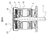
- the cover 22 of the outer fan 21 is attached.
- the end of the cover in the axial direction has a mesh shape so that wind can be sucked in the axial direction.
- FIG. 5A the appearance is not different from the current industrial motor, and the current fan cover can be adopted without adding any parts.
- FIG. 5B shows a cooling air path. The wind from the axial end is changed in the circumferential direction by the radial fan 21 and flows to the motor housing 6 at the heat radiating fin 23 at the end of the heat pipe 10.
- FIG. 6A to 6D show various forms of the radiation fins.
- FIG. 6A shows a configuration in which a plurality of simple disks are stacked to form the fins 23.
- the disk shape shown in FIG. 6A is produced by press punching from a flat plate, so that the material utilization rate is poor.
- FIG. 6B shows a shape in which only holes are processed into a uniform pitch by a press from a thin hoop-shaped member, and the processed product is wound up edgewise to make up for this drawback. . Thereby, the utilization factor of material can be improved markedly.
- FIG. 6C shows a shape in which the divided plates are joined together. This can also be expected to improve material utilization. Moreover, since a step of bending edgewise is not required, it can be manufactured with relatively simple equipment.
- FIG. 6D shows a structure configured as a heat sink block, not a laminated structure.
- a structure in which the surface is provided with irregularities such as groove processing to increase the heat dissipation surface area.
- FIG. 7A and 7B show structural examples of the holding structure for the stator core 1 and the coil 2, the insulating bobbin 27, and the heat pipe 10 of the axial gap motor.
- FIG. 7A shows a magnetic pole structure for one pole of the stator.
- a stator coil 2 is wound around a stator core 1 having a substantially trapezoidal cross section via a resin insulating bobbin 27.
- a heat radiating plate 26 is disposed so as to come into contact with the stator core 1 at a portion of the resin bobbin 27 that is in contact with the housing on the outer diameter side in the circumferential direction.
- the shape of the heat radiating plate 26 is a structure in which a hole for coupling with a heat radiating plate of an adjacent magnetic pole is formed in addition to a hole for positioning with the insulating bobbin 27 of the stator.
- the heat pipe 10 of the present invention is inserted and held in this coupling hole portion with the adjacent magnetic pole.
- the heat sink 26 also has a function of electrically connecting the stator core 1 to a housing component such as a housing to make a ground connection, and the heat sink 26 of each magnetic pole is preferably in contact with the housing.
- FIG. 7B is a sectional view showing the above description. As shown in a cross-sectional view in the lateral direction, the stator core 1 is held by a resin bobbin 27 and has a structure in which the stator core 1 projects beyond the resin bobbin 27 in the upper and lower parts in the axial direction.
- a heat radiating plate 26 is arranged on the flange portion of the protruding resin bobbin 27 on the outer diameter side portion so that the entire length of the resin bobbin 27 and the heat radiating plate 26 is the same as the axial length of the stator core 1. Yes. It can be seen that the insulation distance from the stator coil 2 to the heat radiating plate 26, the housing 6, and the heat pipe 10 can be secured by the presence of the resin bobbin 27.
- an axial gap type rotating electrical machine having one stator in the axial direction and two rotors on both sides of the stator has been described.
- one stator and one rotor in the axial direction are described.
- This heat dissipation structure can also be applied to other axial gap type rotating electrical machines such as an axial gap type rotating electrical machine having
- a heat pipe in which a refrigerant is sealed inside a metal hollow tube is used as a radially outer diameter portion of the stator.
- Place in the gap between adjacent coils and housing with the necessary insulation distance between the coils place one end of the heat pipe on the stator, and extend the other end in the direction of the rotation axis And it is set as the structure fixed in contact with the end bracket on the opposite output side, or it is further extended through the end bracket and brought into contact with the radiation fin.
- the refrigerant sealed inside the heat pipe is warmed by Joule heat generated by the current of the stator coil in a portion close to the stator, the refrigerant evaporates and the vapor moves through the inside of the pipe.
- the heat is released at the portion in contact with the one-side radiating fin, the vapor is condensed and returned to the liquid, so that heat can be efficiently transported between the stator portion and the radiating fin portion.
- FIGS. 8A and 8B show an axial gap type rotating electrical machine in which the arrangement of the heat pipe according to the second embodiment of the present invention is improved.
- the heat pipe is made of a metal member, an eddy current loss is generated in the heat pipe part to some extent due to the influence of the stator magnetic flux of the motor. This eddy current loss is generated as it is closer to the stator coil. For this reason, a contradiction arises that it is preferable to be close to facilitate heat transfer, but is preferable to reduce the loss. Therefore, as a countermeasure, it is necessary to arrange a heat pipe in a portion where eddy current loss is difficult to occur. In the figure, an example of a place where a heat pipe is arranged is shown.
- FIG. 8A shows an example of the winding arrangement of a motor having 9 poles of stator poles.
- a 9-slot motor having 8 or 10 magnet poles the winding arrangement is as shown in FIG. 8A.
- the way the motor current flows at this time is shown by arrows. Since the U-phase motor current always flows in the opposite direction between the U + and U ⁇ coils, the magnetic flux due to the current is canceled out at the center, and the amount of change in the magnetic flux becomes zero. For this reason, it is expected that no eddy current is generated between coils having the same phase and different current directions. For this reason, as shown in the figure, if the heat pipe 10 is disposed only in such a relationship, it is not affected by the eddy current. In the figure, an example is shown in which heat pipes are mounted only at six locations hatched with diagonal lines.
- FIG. 8B illustrates the case of 12 slots (12 stator poles) as described above.
- the coil arrangement as shown in the figure is obtained.
- the coils of each phase are configured such that adjacent coils are energized in opposite directions, so that portions where the in-phase magnetic poles generate current flowing in the opposite direction appear every other place.
- the heat pipe is arranged only between coils having the same phase and different current directions, in addition to the effect of the first embodiment, eddy current loss based on the current flowing through the stator coil can be reduced. Can do.
- FIG. 9A and 9B show an axial gap type motor in which the heat pipe of Example 3 of the present invention is arranged.
- the motor housing 31 shown in FIG. 9A shows a configuration in which a non-conductive and non-magnetic material such as a resin material or ceramic is employed.
- a non-conductive and non-magnetic material such as a resin material or ceramic
- resin materials generally have low thermal conductivity, and resin materials have only 1 W / m ⁇ K, which is about 1/100 that of metallic materials.
- Some ceramic materials such as aluminum nitride are as high as 150 W / m ⁇ K, but materials such as silicon nitride are 20 W / m ⁇ K, which is lower than metal materials.
- the structure has a structure that eliminates heat radiation fins that increase the surface area of the motor housing surface.
- the structure increases the rigidity such as increasing the thickness.
- FIG. 9B shows a cross-sectional view.
- the motor housing 31 is made of a non-conductive and non-magnetic material, and is integrally molded with a resin that molds the stator core and the coil. And the stator core and coil are arrange
- the heat pipe 10 is configured to come into contact with the end bracket 9 and the radiating fins 23 and to be blown by the external fan fan 21 disposed at the end in the axial direction.
- the heat pipe 10 can be configured to have a high-temperature evaporation section and a solidified section where the wind hits the low-temperature section, thereby enabling heat transfer.
- the non-magnetic and non-conductive housing portion 31 of the motor does not generate any eddy current loss caused by the magnetic flux generated by the motor coil, so that the heat generation itself is greatly reduced. .
- the amount of heat transferred and dissipated is only the amount of Joule loss generated from the motor coil and the amount of iron loss generated in the stator core.
- the motor housing 31 is made of the same material as the resin that molds the stator core and the coil and is integrally formed, the stator can be easily manufactured.
- the motor housing portion is made of a non-magnetic and non-conductive material such as resin, eddy current loss generated in the housing portion can be eliminated and the heat dissipation of the rotating electrical machine can be improved.
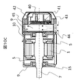
- FIGS. 10A to 10C show a configuration example of an axial gap type motor integrated with a control device according to a fourth embodiment of the present invention.
- the axial gap type motor of this embodiment is a permanent magnet synchronous motor and requires an inverter for its control.
- the permanent magnet synchronous motor is generally used by connecting a general-purpose inverter as a separate cable, but the axial gap type motor described in this embodiment has a magnet and a stator as described in FIG. 3B. Since the facing area of the core can be increased, it is characterized by being relatively thin and capable of obtaining a large torque and a large output.
- the motor portion can be configured to be thin, even if an inverter, which is a control device for controlling the motor, is mounted, for example, at the end in the axial direction, it is almost the same size as a normal industrial motor. It can be.
- FIG. 10A shows a configuration example in which an inverter is attached to an end portion in the axial direction.
- An inverter is mounted on the end of an axial gap type motor, and the inverter is provided with an inverter cover 43 such as the cover of an external fan shown in FIG. It becomes the composition which becomes.
- FIG. 9B shows the inverter mounted state with the cover 43 removed.
- a heat sink 45 for absorbing the heat of the power semiconductor is disposed on the rear end bracket 9 of the motor, and the axial fan 44 for cooling the inverter is placed in the direction of the groove of the heat sink 45, that is, the direction in which the wind easily flows. It arrange
- the inverter control board 40 is mounted on the outer side in the rotation axis direction that is not easily affected by heat from the power elements of the motor and the inverter.
- FIG. 9C shows a cross-sectional view of a motor structure in which the inverter shown in FIG. 9B is mounted.
- the motor unit constitutes an axial gap type motor having two rotor structure yokes 5 with the stator core 1 of the motor as an axial center.
- the heat pipe 10 of the present invention extends through the end bracket 9 in the right direction of the drawing.
- a heat sink 45 is mounted on the end bracket 9, and the heat pipe 10 is in contact with the heat sink 45.
- the heat sink 10 is arranged so that the wind flows upward from below by an axial fan 44 attached to the side.
- a power element 41 such as an IGBT is attached in close contact with the surface of the heat sink 45, and the heat generated there is configured to be easily transmitted to the heat sink 45.
- an inverter control board 40 is formed on the outer side of the power element 41, and a part constituting the inverter control board is covered with an inverter waterproof case 42. This is because the motor is usually a fully-closed type structure, and even if it is used in a place where rainwater enters, the motor must be able to withstand the specifications even when the inverter is mounted.
- inverter cover 43 such as a cover of an external fan
- the direction of the wind flow of the axial fan may be reversed. This is because, in the case of a normal industrial motor, as shown in FIG. 5B, the wind is taken in from the terminal end of the motor and flows to the outer peripheral side and flows to the surface of the housing by a radial fan.
- FIG. 10C since the wind after cooling the power element of the inverter is warm, there is a case where the wind is cooled from the axial fan because it may be counterproductive if it is passed over the motor surface. It is also necessary to take the form of spitting out.
- this motor is a horizontal motor, but due to the nature of the heat pipe, the vapor evaporated in the evaporation section rises, and the liquid that has become liquid in the evaporation section moves downward due to gravity.
- a structure is desirable, as described above, in a heat pipe, a thin line called a wick and an inner ridge can be expected to transfer liquid to a low-density part by capillary action, so it can be placed horizontally. The vaporized liquid can be expected to return to the high temperature part and evaporate.
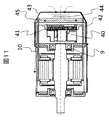
- Fig. 11 shows another configuration of an axial gap type motor on which an inverter is mounted.
- a heat sink is arranged on the end bracket 9 of the motor, the heat of the power element of the inverter is transmitted to the motor, which may increase the temperature of the motor unit and the bearing.
- a waterproof inverter chamber is provided outside the end bracket 9 of the motor, and the power element 41 of the inverter is mounted toward the end portion.
- the heat sink 45 or the heat radiating fin is disposed on the terminal end side, the waterproof fan 44 is mounted on the outer side, and the structure is covered with the fan cover 43.
- the heat pipe 10 of the present embodiment is configured to extend to the heat sink 45 at the re-termination part and to contact the heat sink 45.
- the direction of the wind of the external fan 44 may be either, but as described above, it is desirable to determine it depending on the temperature of the power element.
- a control device such as an inverter is integrally attached to the axial end portion of the axial gap type motor, thereby providing a motor that is almost the same size as a normal industrial motor and is easy to carry. can do.
- FIG. 12 shows an axial gap type motor in which mechanical parts are integrated and mounted on the motor according to the fifth embodiment of the present invention.
- FIG. 12 shows an example in which the pump is integrated.
- the axial gap type motor has an advantage that the motor body is thin, so that integration with mechanical parts can be made compact.
- the rotary shaft 7 is connected to the impeller 32 of the pump through a pump chamber 33 in which water enters the shaft end of the motor and a partition wall 38 for isolating the motor portion.
- Reference numeral 34 represents a pump case.
- the heat pipe 10 of the present embodiment is mounted by extending through the partition wall 38 to the pump chamber 33 containing water.
- the axial gap type motor is constructed without integrating the pump into the axial end portion of the axial gap type motor and extending the heat pipe provided in the stator to the pump chamber. Can greatly improve the heat dissipation.
Landscapes
- Engineering & Computer Science (AREA)
- Power Engineering (AREA)
- Mechanical Engineering (AREA)
- General Engineering & Computer Science (AREA)
- Physics & Mathematics (AREA)
- Thermal Sciences (AREA)
- Life Sciences & Earth Sciences (AREA)
- Sustainable Development (AREA)
- Microelectronics & Electronic Packaging (AREA)
- Motor Or Generator Cooling System (AREA)
- Permanent Magnet Type Synchronous Machine (AREA)
Abstract
La présente invention vise à améliorer considérablement la propriété de libération de chaleur d'une machine électrique tournante de type à entrefer axial dans les dimensions physiques nécessaires pour constituer un moteur. Dans une machine électrique tournante de type à entrefer axial possédant un stator et un rotor dans la direction axiale, le stator est formé en disposant une pluralité de noyaux de stator dans la direction circonférentielle et en enroulant des bobines autour des noyaux de stator. Un caloduc formé en enfermant un fluide frigorigène à l'intérieur d'un tuyau creux métallique est disposé dans un espace entre des bobines adjacentes et un boîtier par fixation d'une distance d'isolation nécessaire entre les bobines et le caloduc, ledit espace étant formé au niveau d'une partie de diamètre extérieur du stator dans la direction radiale. Le caloduc est étendu dans la direction de l'axe de rotation et la direction opposée côté sortie et entre en contact avec une ailette de dissipateur thermique à l'extérieur du support d'extrémité du côté sortie opposé.
Priority Applications (3)
| Application Number | Priority Date | Filing Date | Title |
|---|---|---|---|
| PCT/JP2016/055676 WO2017145333A1 (fr) | 2016-02-25 | 2016-02-25 | Machine électrique tournante de type à entrefer axial |
| US16/078,298 US10566876B2 (en) | 2016-02-25 | 2016-02-25 | Axial gap rotary electric machine |
| JP2018501505A JP6653011B2 (ja) | 2016-02-25 | 2016-02-25 | アキシャルギャップ型回転電機 |
Applications Claiming Priority (1)
| Application Number | Priority Date | Filing Date | Title |
|---|---|---|---|
| PCT/JP2016/055676 WO2017145333A1 (fr) | 2016-02-25 | 2016-02-25 | Machine électrique tournante de type à entrefer axial |
Publications (1)
| Publication Number | Publication Date |
|---|---|
| WO2017145333A1 true WO2017145333A1 (fr) | 2017-08-31 |
Family
ID=59686016
Family Applications (1)
| Application Number | Title | Priority Date | Filing Date |
|---|---|---|---|
| PCT/JP2016/055676 Ceased WO2017145333A1 (fr) | 2016-02-25 | 2016-02-25 | Machine électrique tournante de type à entrefer axial |
Country Status (3)
| Country | Link |
|---|---|
| US (1) | US10566876B2 (fr) |
| JP (1) | JP6653011B2 (fr) |
| WO (1) | WO2017145333A1 (fr) |
Cited By (6)
| Publication number | Priority date | Publication date | Assignee | Title |
|---|---|---|---|---|
| JP2019140792A (ja) * | 2018-02-09 | 2019-08-22 | 株式会社神戸製鋼所 | アキシャルギャップ型回転電機 |
| CN113098177A (zh) * | 2021-04-07 | 2021-07-09 | 清华大学 | 用于内转子电机的定子散热结构、内转子电机及涵道风扇 |
| JP2023023564A (ja) * | 2021-08-05 | 2023-02-16 | 日本電産株式会社 | モータ |
| JP2023047731A (ja) * | 2021-09-27 | 2023-04-06 | 株式会社デンソー | 回転電機ユニット |
| KR20230059928A (ko) * | 2021-10-26 | 2023-05-04 | 한국생산기술연구원 | 방열핀 및 펌핑자 구조를 적용한 afpm 모터 |
| JP2023523905A (ja) * | 2020-04-30 | 2023-06-08 | トゥラ イーテクノロジー,インコーポレイテッド | 共通シャフトを駆動するための磁気的に結合解除された別個に制御されている複数電気機械組立体 |
Families Citing this family (41)
| Publication number | Priority date | Publication date | Assignee | Title |
|---|---|---|---|---|
| DE102015219951B4 (de) * | 2015-10-14 | 2022-02-17 | Lenze Se | Elektromotor |
| US10840771B2 (en) * | 2016-09-28 | 2020-11-17 | Mitsubishi Electric Corporation | Motor, blower, air conditioner, and method of producing motor |
| JP6595443B2 (ja) * | 2016-12-01 | 2019-10-23 | トヨタ自動車株式会社 | 回転電機 |
| US11139722B2 (en) * | 2018-03-02 | 2021-10-05 | Black & Decker Inc. | Motor having an external heat sink for a power tool |
| US12311772B2 (en) | 2018-03-19 | 2025-05-27 | Tula eTechnology, Inc. | Pulse modulated control with field weakening for improved machine efficiency |
| JP7082679B2 (ja) | 2018-03-19 | 2022-06-08 | トゥラ イーテクノロジー,インコーポレイテッド | パルス化電気機械制御 |
| US10944352B2 (en) | 2018-03-19 | 2021-03-09 | Tula eTechnology, Inc. | Boosted converter for pulsed electric machine control |
| US11623529B2 (en) | 2018-03-19 | 2023-04-11 | Tula eTechnology, Inc. | Pulse modulated control with field weakening for improved motor efficiency |
| US12609646B2 (en) | 2018-03-19 | 2026-04-21 | Tula eTechnology, Inc. | Boosted converter for pulsed electric machine control |
| HU231243B1 (hu) * | 2019-01-25 | 2022-04-28 | Wigner Fizikai Kutatóközpont | Eljárás toroid transzformátor tekercsének szigetelésére |
| US11152842B2 (en) * | 2019-06-13 | 2021-10-19 | Win Kai | Electromagnetic motor and generator |
| US11616410B2 (en) * | 2020-01-10 | 2023-03-28 | Samsung Electronics Co., Ltd. | Cleaner |
| CN112202303B (zh) * | 2020-08-24 | 2022-03-08 | 浙江中博传动科技有限公司 | 一种高强度电动机定子 |
| US11628730B2 (en) | 2021-01-26 | 2023-04-18 | Tula eTechnology, Inc. | Pulsed electric machine control |
| US12319147B2 (en) | 2021-01-26 | 2025-06-03 | Tula eTechnology, Inc. | Pulsed electric machine control |
| US11637513B2 (en) | 2021-03-15 | 2023-04-25 | Tula eTechnology, Inc. | Methods of optimizing waveforms for electric motors |
| CN112821674B (zh) * | 2021-03-30 | 2021-12-03 | 鹤山市长鸿电机有限公司 | 一种便于维护且散热效果好的电机 |
| KR20240021165A (ko) | 2021-06-14 | 2024-02-16 | 툴라 이테크놀로지 아이엔씨. | 효율적인 토크 이행을 갖춘 전기 머신 |
| WO2023278139A1 (fr) | 2021-06-28 | 2023-01-05 | Tula eTechnology, Inc. | Commande de phase sélective d'une machine électrique |
| US11557996B1 (en) | 2021-07-08 | 2023-01-17 | Tula eTechnology, Inc. | Methods of reducing vibrations for electric motors |
| CN115706460A (zh) * | 2021-08-09 | 2023-02-17 | 浙江大学 | 电机及电机的加工装配方法 |
| US11345241B1 (en) | 2021-08-12 | 2022-05-31 | Tula eTechnology, Inc. | Method of optimizing system efficiency for battery powered electric motors |
| JP7781569B2 (ja) * | 2021-09-08 | 2025-12-08 | ニデック株式会社 | モータ |
| US11916498B2 (en) | 2021-09-08 | 2024-02-27 | Tule eTechnology Inc. | Electric machine torque adjustment based on waveform integer multiples |
| WO2023064226A1 (fr) | 2021-10-11 | 2023-04-20 | Tula eTechnology, Inc. | Commande pulsée de multiples machines électriques |
| WO2023069131A1 (fr) | 2021-10-18 | 2023-04-27 | Tula eTechnology, Inc. | Dispositifs mécaniques et électromécaniques pour affaiblir le champ d'une machine électrique qui fait appel à des aimants permanents |
| CN118830193A (zh) | 2022-03-22 | 2024-10-22 | 图拉技术公司 | 脉冲绕线式励磁同步机的延迟降低 |
| US12601352B2 (en) | 2022-05-03 | 2026-04-14 | General Electric Company | High pressure magnetic coupling shrouds and methods of producing the same |
| US12448978B2 (en) | 2022-05-03 | 2025-10-21 | General Electric Company | Layered barrier cans for pumps and methods of producing the same |
| US12460647B2 (en) | 2022-05-03 | 2025-11-04 | General Electric Company | Integrated bearing systems for dynamically supporting shafts in pump systems |
| US12421968B2 (en) * | 2022-05-03 | 2025-09-23 | General Electric Company | Axial flux motor driven pump systems for pressurizing fluid in closed loop systems |
| CN114884261B (zh) * | 2022-05-09 | 2023-09-12 | 南京玛格耐特智能科技有限公司 | 一种具有散热和降噪功能的永磁直驱电机 |
| CN114844270B (zh) * | 2022-05-13 | 2024-12-20 | 宁波诺丁汉大学 | 一种定子组件及电机 |
| CN114785051B (zh) * | 2022-06-20 | 2022-08-26 | 沈阳工业大学 | 一种永磁电机的热管冷却结构及电机 |
| KR20250034022A (ko) | 2022-07-08 | 2025-03-10 | 툴라 이테크놀로지 아이엔씨. | 전기 기계 구동 교정, 검증 및 효율 개선 |
| US12244250B2 (en) | 2022-07-18 | 2025-03-04 | Tula eTechnology, Inc. | Feedback scaling for electric machines |
| US11888424B1 (en) | 2022-07-18 | 2024-01-30 | Tula eTechnology, Inc. | Methods for improving rate of rise of torque in electric machines with stator current biasing |
| US12424962B2 (en) | 2022-07-18 | 2025-09-23 | Tula eTechnology, Inc. | Pulsed electric machine control with soft start and end |
| JP2025528312A (ja) | 2022-08-22 | 2025-08-28 | トゥラ イーテクノロジー,インコーポレイテッド | パルス化電気機械の効率を改善するための昇圧ロータ供給回路および方法 |
| US12331781B2 (en) | 2023-02-03 | 2025-06-17 | General Electric Company | Dual thrust bearing systems and methods for operating the same |
| US12370907B2 (en) | 2023-10-17 | 2025-07-29 | Tula eTechnology, Inc. | On-pulse transition times for pulsed controlled electric machines using boost voltages |
Citations (3)
| Publication number | Priority date | Publication date | Assignee | Title |
|---|---|---|---|---|
| JP2006094664A (ja) * | 2004-09-27 | 2006-04-06 | Nissan Motor Co Ltd | アキシャルギャップ型回転電機のステータ構造 |
| JP2009190578A (ja) * | 2008-02-14 | 2009-08-27 | Toyota Motor Corp | 車両用のインホイールモータ |
| US20130187484A1 (en) * | 2012-01-20 | 2013-07-25 | Wen-Hao Liu | Motor stator with heat dissipation structure |
Family Cites Families (7)
| Publication number | Priority date | Publication date | Assignee | Title |
|---|---|---|---|---|
| US6211587B1 (en) * | 1998-11-12 | 2001-04-03 | Hitachi, Ltd. | Electric rotating machine |
| US6633098B2 (en) * | 2001-08-29 | 2003-10-14 | Hitachi, Ltd. | Alternator for use in a vehicle |
| JP2006204085A (ja) * | 2004-12-24 | 2006-08-03 | Sumitomo Electric Ind Ltd | アキシャルギャップ型超電導モータ |
| JP2008072881A (ja) * | 2006-09-15 | 2008-03-27 | Toyota Motor Corp | モータ |
| JP4935285B2 (ja) | 2006-10-04 | 2012-05-23 | 日産自動車株式会社 | アキシャルギャップ型回転電機のステータ構造 |
| JP5635921B2 (ja) | 2011-01-26 | 2014-12-03 | 株式会社日立産機システム | モータユニットおよびこれを用いた回転電機、回転電機装置 |
| JP5965228B2 (ja) | 2012-07-06 | 2016-08-03 | 株式会社日立製作所 | アキシャルギャップ型回転電機 |
-
2016
- 2016-02-25 WO PCT/JP2016/055676 patent/WO2017145333A1/fr not_active Ceased
- 2016-02-25 JP JP2018501505A patent/JP6653011B2/ja not_active Expired - Fee Related
- 2016-02-25 US US16/078,298 patent/US10566876B2/en not_active Expired - Fee Related
Patent Citations (3)
| Publication number | Priority date | Publication date | Assignee | Title |
|---|---|---|---|---|
| JP2006094664A (ja) * | 2004-09-27 | 2006-04-06 | Nissan Motor Co Ltd | アキシャルギャップ型回転電機のステータ構造 |
| JP2009190578A (ja) * | 2008-02-14 | 2009-08-27 | Toyota Motor Corp | 車両用のインホイールモータ |
| US20130187484A1 (en) * | 2012-01-20 | 2013-07-25 | Wen-Hao Liu | Motor stator with heat dissipation structure |
Cited By (10)
| Publication number | Priority date | Publication date | Assignee | Title |
|---|---|---|---|---|
| JP2019140792A (ja) * | 2018-02-09 | 2019-08-22 | 株式会社神戸製鋼所 | アキシャルギャップ型回転電機 |
| JP6993892B2 (ja) | 2018-02-09 | 2022-01-14 | 株式会社神戸製鋼所 | アキシャルギャップ型回転電機 |
| JP2023523905A (ja) * | 2020-04-30 | 2023-06-08 | トゥラ イーテクノロジー,インコーポレイテッド | 共通シャフトを駆動するための磁気的に結合解除された別個に制御されている複数電気機械組立体 |
| CN113098177A (zh) * | 2021-04-07 | 2021-07-09 | 清华大学 | 用于内转子电机的定子散热结构、内转子电机及涵道风扇 |
| CN113098177B (zh) * | 2021-04-07 | 2023-03-28 | 清华大学 | 用于内转子电机的定子散热结构、内转子电机及涵道风扇 |
| JP2023023564A (ja) * | 2021-08-05 | 2023-02-16 | 日本電産株式会社 | モータ |
| JP7705752B2 (ja) | 2021-08-05 | 2025-07-10 | ニデック株式会社 | モータ |
| JP2023047731A (ja) * | 2021-09-27 | 2023-04-06 | 株式会社デンソー | 回転電機ユニット |
| KR20230059928A (ko) * | 2021-10-26 | 2023-05-04 | 한국생산기술연구원 | 방열핀 및 펌핑자 구조를 적용한 afpm 모터 |
| KR102601125B1 (ko) * | 2021-10-26 | 2023-11-14 | 한국생산기술연구원 | 방열핀 및 펌핑자 구조를 적용한 afpm 모터 |
Also Published As
| Publication number | Publication date |
|---|---|
| US10566876B2 (en) | 2020-02-18 |
| US20190058374A1 (en) | 2019-02-21 |
| JPWO2017145333A1 (ja) | 2018-12-13 |
| JP6653011B2 (ja) | 2020-02-26 |
Similar Documents
| Publication | Publication Date | Title |
|---|---|---|
| JP6653011B2 (ja) | アキシャルギャップ型回転電機 | |
| JP5216038B2 (ja) | 回転電動機 | |
| JP5649737B2 (ja) | 機電一体型モジュール | |
| US10277096B2 (en) | System for thermal management in electrical machines | |
| JP5553040B2 (ja) | 電子部品 | |
| CN105103409A (zh) | 用于轴向电机的极靴冷却间隙 | |
| CN107959381A (zh) | 包括用于通过空气进行内部冷却的系统的封闭式旋转电机 | |
| JP2010154713A (ja) | 電動機用ステータ及び電動機用分割ステータ | |
| JP6044848B2 (ja) | 回転電機 | |
| JP2020014283A (ja) | 回転電機のステータ構造及びこれを備えた車両 | |
| JP2014023198A (ja) | 電動機 | |
| CN103618394B (zh) | 一种采用热管绕组的盘式电机定子 | |
| JP7705752B2 (ja) | モータ | |
| JP2011172464A (ja) | 回転電機の固定子 | |
| JP6768142B2 (ja) | アキシャルギャップ型回転電機 | |
| JP2015170674A (ja) | リアクトル | |
| CN105284032B (zh) | 电动机 | |
| JP2009268327A (ja) | ブラシレスモータ | |
| JP2009130958A (ja) | 回転電機 | |
| TWI572125B (zh) | Rotor heat dissipation structure of inner rotor motor | |
| WO2015037069A1 (fr) | Machine dynamo-électrique | |
| CN120281125A (zh) | 轴向磁通电机 | |
| JP2024157152A (ja) | モータ | |
| CN112467942B (zh) | 散热式轴向电机 | |
| JP2019054632A (ja) | 回転電機 |
Legal Events
| Date | Code | Title | Description |
|---|---|---|---|
| WWE | Wipo information: entry into national phase |
Ref document number: 2018501505 Country of ref document: JP |
|
| NENP | Non-entry into the national phase |
Ref country code: DE |
|
| 121 | Ep: the epo has been informed by wipo that ep was designated in this application |
Ref document number: 16891490 Country of ref document: EP Kind code of ref document: A1 |
|
| 122 | Ep: pct application non-entry in european phase |
Ref document number: 16891490 Country of ref document: EP Kind code of ref document: A1 |