WO2017145424A1 - Unité de rouleau d'une machine d'ensemencement pour boîte de pépinière - Google Patents
Unité de rouleau d'une machine d'ensemencement pour boîte de pépinière Download PDFInfo
- Publication number
- WO2017145424A1 WO2017145424A1 PCT/JP2016/077836 JP2016077836W WO2017145424A1 WO 2017145424 A1 WO2017145424 A1 WO 2017145424A1 JP 2016077836 W JP2016077836 W JP 2016077836W WO 2017145424 A1 WO2017145424 A1 WO 2017145424A1
- Authority
- WO
- WIPO (PCT)
- Prior art keywords
- feeding
- feeding roll
- roll unit
- seed
- seedling box
- Prior art date
- Legal status (The legal status is an assumption and is not a legal conclusion. Google has not performed a legal analysis and makes no representation as to the accuracy of the status listed.)
- Ceased
Links
Images


Classifications
-
- A—HUMAN NECESSITIES
- A01—AGRICULTURE; FORESTRY; ANIMAL HUSBANDRY; HUNTING; TRAPPING; FISHING
- A01C—PLANTING; SOWING; FERTILISING
- A01C7/00—Sowing
- A01C7/08—Broadcast seeders; Seeders depositing seeds in rows
-
- A—HUMAN NECESSITIES
- A01—AGRICULTURE; FORESTRY; ANIMAL HUSBANDRY; HUNTING; TRAPPING; FISHING
- A01C—PLANTING; SOWING; FERTILISING
- A01C7/00—Sowing
- A01C7/08—Broadcast seeders; Seeders depositing seeds in rows
- A01C7/12—Seeders with feeding wheels
Definitions
- the present invention provides a seeding device for a seedling box for seeding seeds such as paddy rice seeds, in order to facilitate maintenance in the part of the feeding roll that feeds seeds such as seed seeds. Further, the present invention relates to a roll unit of a seedling box seeder that can be detached from the seeder.
- the feeding roll, the guide guide of the seed held in the groove-shaped feeding recess of the feeding roll, and the lower part of the feeding roll fitted in the slit of the feeding roll It is very difficult to remove the foreign material scraping fork from the seeding device, and it takes time to perform maintenance when a malfunction occurs during use, cleaning after use, and replacement of parts when a malfunction occurs. There was.
- the present invention intends to solve such problems.
- a feeding roll for holding a fixed amount of seeds in the groove-shaped feeding recess and holding the seed fitted in the groove-shaped feeding recess from above
- a feeding roll unit is configured by being integrally supported between the plates, and the feeding roll unit is configured to be detachable between a pair of frame side plates of the seeding device.
- an engagement shaft hole is provided inside the bearing of the feeding roll supported by the bearing between the pair of plates.
- An engagement rotation shaft is provided to connect the shaft hole and an engagement shaft hole of a drive sprocket for driving disposed outside the frame side plate, and the engagement rotation shaft can be pulled out by an engagement shaft pull-out member.
- the feeding roll unit can be separated from the frame of the seeding device and the gear of the seeding device by pulling out the engagement rotation shaft.
- the feeding roll unit is inserted into and removed from the front side in the traveling direction of the seedling box between the pair of frame side plates.
- the opening part for this is comprised.
- the seed rotating brush that rotates in contact with the outer periphery of the feeding roll and sweeps back the seed in the hopper is the pair of frame side plates.
- the outer side of the feeding roll unit and the outer circumference of the seed rotating brush can be brought into contact with the insertion of the feeding roll unit.
- a feeding roll that holds a fixed amount of seeds in the groove-shaped feeding recesses and a seed fitted in the groove-shaped feeding recesses from above.
- the feeding roll unit is integrally supported between the plates, and the feeding roll unit is configured to be detachable between the pair of frame side plates of the seeding device, the feeding roll configured as the feeding roll unit, foreign matter Since the scraping fork and the seed guide can be removed integrally, the time required for maintenance can be greatly saved.
- an engagement shaft hole is provided inside the bearing of the feeding roll supported by the bearing between the pair of plates, and the drive shaft is disposed outside the engagement shaft hole of the bearing and the frame side plate.
- An engagement rotation shaft that connects with an engagement shaft hole of the drive sprocket is provided, the engagement rotation shaft can be pulled out by an engagement shaft pull-out member, and the engagement rotation shaft is pulled out, whereby the feeding roll unit Can be separated from the frame of the seeding device and the gear of the seeding device, so that the seeding device fixed to the drive rail and the feeding roll unit can be separated only by pulling out the engagement shaft pull-out member. It became easy to do.
- the opening part for inserting / removing the feeding roll unit is formed on the front side in the moving direction of the seedling box between the pair of frame side plates, the feeding roll unit is inserted / removed from the opening part. This eliminates the need for disassembling the seeding device and facilitates maintenance. Further, the opening can be closed by a front plate constituting the feeding roll unit, and this front plate can be used as a mounting portion for the feeding roll unit.
- a seed rotating brush that rotates in contact with the outer periphery of the feeding roll and sweeps back the seed in the hopper is supported by bearings on the side of the pair of frame side plates, along with the insertion of the feeding roll unit, Since the outer periphery of the feeding roll and the outer periphery of the seed rotating brush can be brought into contact with each other, it is not necessary to integrate the seed rotating brush into the feeding roll unit, the structure of the feeding roll unit is simplified, and the feeding roll When the unit is removed, the seed rotating brush and the feeding roll are separated from each other, so that it becomes easy to check the wear state between them and perform maintenance.
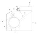
- Side perspective view of the seeding device in the seedling box seeder.
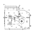
- Left side view in the direction of travel of the seedling box of the feeding roll unit The front view of the state which inserted and fixed the feeding roll unit in the opening part between flame
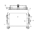
- the perspective view of the engagement rotating shaft inserted between the engagement bearing of a delivery roll unit, and the engagement shaft of a drive sprocket.
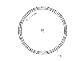
- the front view of the feeding roll which comprises a feeding roll unit.
- the drawing which shows the inclination structure of a groove shape feeding recessed part in the left side plate of a feeding roll.
- the drawing which shows arrangement
- Sectional drawing along the axial center direction of a feeding roll which shows the shape of the scraping fork recessed part in a feeding roll.
- Sectional drawing of the direction orthogonal to the axial center direction of a feeding roll which shows the shape of the groove shape feeding recessed part in a feeding roll.
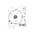
- the side view which shows the contact state of the seed rotation brush and feeding roll unit which comprise a feeding roll unit.
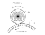
- the drawing which shows the seed rotating brush which contacts and rotates with respect to a feeding roll, and returns the overflowing seed which is not inserted in the groove shape feeding recessed part to the seed hopper side with the seed of a seed hopper.
- FIG. 1 the overall structure of the seeding device of the rice seedling box seeder will be described.
- the seeding device of the seedling machine for paddy rice seedling box moves the seedling box on the driving rail R for transporting the seedling box at the time of sowing.
- a floor soil supply device A, a seeding device B, and a soil covering device C are fixedly arranged on the drive rail R in order along the conveying direction of the seedling box. While the seedling box is driven and transferred by the driving roll 5 on the driving rail R, the floor soil is put into the seedling box by the floor soil supply device A, and the leveling device E is placed on the floor soil. Then, irrigation is performed by the irrigation device D, then seeds are sown by the sowing device B, and further, the soil is covered on the floor soil and seeds by the soil covering device C, sowing work. Is configured to end.
- H is a driving device for the floor soil supply device A.
- the drive device of the floor soil supply device A that transmits power to the drive rail R and the floor soil supply device A at a position in front of the floor soil supply device A. H is disposed, and further, a leveling device E for leveling the soil surface and a irrigation device D are disposed at the rear of the floor soil supply device A.
- the present invention relates to a support structure for facilitating the maintenance of the feeding roll K that constitutes the main part of the sowing apparatus B in the sowing apparatus for the sowing machine for paddy rice seedling boxes.
- the seeding device B arranges a seed hopper 18 at the top, and puts seed pods, which are seeds of paddy rice to be sown, into the seed hopper 18.
- a shutter 40 is disposed below the seed hopper 18, and a shutter operation unit 39 that opens and closes the shutter 40 is provided. The seed that has fallen from the shutter 40 moves to the space between the feeding roll K and the seed rotating brush 33, and a part of the seed falls into the groove-shaped feeding recess 8 around the feeding roll K.
- the seeds overflowing around the feeding roll K without being inserted into the groove-shaped feeding recess 8 formed on the right and left sides in the direction perpendicular to the advancing direction of the nursery box are illustrated in FIG. 20 together with the rotation of the feeding roll K. As shown, it is scraped off by the seed rotating brush 33 rotating in the direction opposite to the rotation direction V of the feeding roll K and returns to the lower part of the seed hopper 18.
- the seed hopper 18 is supported between the left and right frame side plates 4L and 4R constituting the seeding device B, and a drive motor is fixed inside the frame side plates 4L and 4R to drive the drive motor.
- Power is transmitted from the motor shaft 32 through the motor sprocket 36 to the counter sprocket 37 of the counter shaft 38 by a chain.
- a chain 70 is wound from the counter sprocket 37 to the drive sprocket 34 of the feeding roll K to transmit power.
- the drive sprocket 34 is supported by a hexagonal rotating cylinder shaft 11 which is an engaging rotating cylinder shaft between the sprocket support plate 41 and the frame side plate 4R. That is, the hexagonal rotating cylinder shaft 11 which is the engaging rotating cylinder shaft is installed between the bearing 43 of the frame side plate 4R and the bearing 42 of the sprocket support plate 41 so as to support the bearing.
- the drive sprocket 34 is fixed on the outer periphery and is rotatable.
- the hexagonal rotation cylindrical shaft 11 passes through the hexagonal hole and can be further inserted into the hexagonal hole of the cylindrical shaft 14a fitted into the inner ring of the hexagonal bearing 14 of the roll side plates 17L and 17R constituting the feeding roll unit U.
- the rotary shaft pulling member 16 is pressed to the outside of the hexagonal rotary cylinder shaft 11 and is fixed by a fixing screw 16a.
- the rotary shaft pullout member 16 is driven together with the hexagonal rotary cylinder shaft 11 and the drive sprocket 34. When the sprocket 34 is rotated, it is also rotating.
- the hexagonal rotary shaft 15 is pulled out from the cylindrical shaft 14 a of the hexagonal hole bearing 14 by the rotary shaft pulling member 16, so that the driving coupling state between the feeding roll unit U, the feeding roll K, and the drive sprocket 34 is achieved. Is released, and the feeding roll unit U can be taken out from the opening Q in front of the sowing apparatus B.
- the other side opposite to the side where the rotary shaft drawing member 16 of the feeding roll unit U is provided is configured to be able to easily release the bearing state of the feeding roll unit U, from the side of the rotary shaft drawing member 16.
- the attaching screw 16a is disposed inside the hexagonal hole 11a having the inner diameter of the hexagonal rotating cylinder shaft 11.
- the urging spring S presses the hexagon rotating shaft 15 to press the entire feeding roll unit U toward the left roll side plate 17L, and the left bearing portion is easily engaged so that the feeding roll K can be rotated. Is supported by the bearing.
- the feeding roll unit U includes left and right roll side plates 17L and 17R, a feeding roll K, a seed guide guide 35, and a foreign matter scraping fork 2 that are integrally structured between the left and right roll side plates 17L and 17R.
- the seed guide 35 and the foreign material scraping fork 2 are installed on the frame side plates 4L and 4R of the seeding device B, and only the feeding roll K is rotatably supported by the frame side plates 4L and 4R. It is.
- the roll side plates 17L and 17R are arranged inside the frame side plates 4L and 4R, and the foreign matter raking fork 2 and the seed guide guide 35 are fixed between the roll side plates 17L and 17R, and the feeding roll K As a whole, a feeding roll unit U that can be taken out from the opening Q is configured.
- the opening Q of the seeding device B is closed by the rear plate 1 of the feeding roll unit U, and the feeding roll unit U can be fixed by attaching the rear plate 1 to the seeding device B.
- the feeding roll unit U configured in this way can be inserted and removed from the opening Q on the front side of the seeding device B, and the hexagonal rotating shaft 15 is pulled out by the rotating shaft pulling member 16 from the state of FIG.
- the hexagonal rotary shaft 15 can be pulled out in the state of 10 so that the power transmission state between the drive sprocket 34 and the feeding roll K can be disconnected and connected.
- the seed guide 35 constituting the feeding roll unit U is shown in FIG. 21 and is formed in a semicircular cylindrical shape along the outer periphery of the feeding roll K. Further, as shown in FIG. 22, the foreign matter scraping fork 2 is provided with a teardrop-shaped plate as many as the number of the scraping fork concave portions 9 of the feeding roll K between the support shafts 2a and 2b.
- the left and right roll side plates 17L and 17R are configured to reach the width of the left and right roll side plates 17L and 17R. .
- the scraping fork recess 9 has a width of 7.15 mm and 40 holes are perforated, and the foreign matter scraping fork 2 is also 7.15 mm. Forty widths, 40 pieces are fixed at the same interval between the roll side plates 17L and 17R as a set.
- the special structure of the feeding roll K will be described.
- the groove-shaped feeding recess 8 into which seeds are fitted is formed in the same direction as the rotation axis of the feeding roll K in parallel with the bus W W at an angle of 6 °.
- the book was pierced.
- the known feeding roll has a horizontal groove-shaped feeding recess parallel to the bus W direction on the outer peripheral surface of the feeding roll.
- the seed rotating brush 33 that sweeps back the seed pods in the hopper is always in close contact with the outer peripheral surface of the feeding roll and rotates.
- the conventional known roll has a problem of causing a bridge during high-speed rotation because it only has a feed groove having a horizontal groove shape parallel to the direction of the bus W on the outer peripheral surface of the roll.
- all of the feeding roll K configured in an oblique, screw groove shape inclined from the left and right end portions to the end portions by 8.1 degrees with respect to the bus W.
- the 60 groove-shaped feeding recesses 8 are all configured as screw grooves inclined in the same direction.
- the configuration of the terminal portions of the left and right end portions of the groove-shaped feeding recess 8 at the left and right end portions of the feeding roll K is that the groove has been terminated at a stretch in the past.
- the width gradually decreases between 2 and 3 at the left and right end portions of the 40 scraped fork recesses 9 formed in the periphery, and the depth is reduced. It is structured so that it becomes shallow and ends and disappears. Also by this, it was possible to configure so that the seeds could enter the groove-shaped feeding recess 8 and could be easily dropped at the dropping portion.
- the groove-shaped feeding recess 8 around the feeding roll K has a cross-sectional shape as shown in FIG. 19 in the section in the rotational axis direction. That is, the groove-shaped feeding recess 8 is a substantially U-shaped groove in a cross-sectional view into which seeds are inserted, and is a circular arc having a radius of 2.5 mm, and is straight and flat from the middle part toward the front in the rotation direction V. The portion is shaped by chamfering 3.34 mm at an angle of 45 degrees.
- a rear side chamfered portion 8b having a depth of about 1 mm and an angle of 45 degrees is also formed on the rear side in the rotation direction V of the groove-shaped feeding recess 8 at the final outlet side.
- the rear side chamfered portion 8b of the groove-shaped feeding concave portion 8 has a shape in which the curved surface is chamfered so that the seed does not fall backward from the concave portion.
- the chamfering of the horizontal groove is performed only in the rotation direction V, and the fitted seed is not dropped backwards.
- the seed guiding surface to the recess of the groove is narrow, so the seed fits well.
- the present invention relates to a seeding device for a seedling machine for paddy rice seedling boxes, a drive unit for transporting the seedling box, a floor soil supply device A for putting floor soil into the seedling box in the middle of the transport, and the floor soil supply device A Irrigation device D for irrigating from the upper surface of the soil after passing through the soil, sowing device B for sowing a prescribed amount of paddy rice seed on the ground soil after irrigation, and a covering device C for removing the defined amount of covering soil from the upper surface after sowing
- a seedling box seeding machine for paddy rice a feeding roll K, a foreign matter scraping fork 2, and a seed guide guide 35 for guiding seeds fitted to a seeding roller from the upper part to the lower part have an integrated structure, sowing
- the structure can be separated from the frame of the apparatus and the gear of the seeding apparatus B.
- the feeding roll K, the fork F, and the roll guide L are sandwiched between the left and right plates 3L and 3R, and a hexagonal hole bearing 14 is provided at the center of the side surface of the feeding roll K.
- the left and right frame side plates 4L and 4R and the gears 15 are separated from each other. That is, the hexagonal rotary shaft 15 fitted to the cylindrical shaft 14a fixed to the inner ring of the hexagonal hole bearing 14 at the center of the roll side plates 17L and 17R constituting the side plate of the feeding roll K is provided in the frame side plates 4L and 4R of the seeding device B. This structure is connected to the rotating drive sprocket 34.
- the feeding roll K, the fork F, and the roll guide L are sandwiched between the left and right plates 3L and 3R, and the hexagonal hole bearing 14 is provided at the center of the side surface of the feeding roll K.
- the left and right frame side plates 4 ⁇ / b> L and 4 ⁇ / b> R and the drive sprocket 34 are configured to be separated from each other. That is, the hexagonal rotating shaft 15 fitted to the cylindrical shaft 14a fixed to the inner ring of the hexagonal hole bearing 14 at the center of the roll side plates 17L and 17R constituting the side plate of the feeding roll K is fixed to the frame side plates 4L and 4R.
- the drive sprocket 34 is connected.
- a groove-shaped feeding recess 8 that is slanted with respect to the direction of the bus W is formed on the entire outer circumference of the feeding roll K. That is, the screw structure.
- a scraped fork recess 9 into which the fork F is fitted is opened on the outer peripheral surface of the roll.
- the slanted groove-shaped feeding recess 8 has a shape in which chamfering 8a and 8b are applied to the curved surface so that the seed does not fall backward from the recess.
- the present invention provides a feeding roll K that holds a fixed amount of seeds in the groove-shaped feeding recess 8 and holds the seeds fitted in the groove-shaped feeding recess 8 from above.
- the fork 2 is composed of a feeding roll unit U that is integrally supported between the plates 3L and 3R, and the feeding roll unit U is detachable between the frame side plates 4L and 4R of the seeding device B. .
- a cylindrical shaft 14a is provided inside the hexagonal hole bearing 14 of the feeding roll K supported between the plates 3L and 3R of the feeding roll unit U, and the frame side plate 4L of the seeding device B is provided on the cylindrical shaft 14a.
- a hexagonal rotary shaft 15 that connects the hexagonal hole 11a of the hexagonal rotary cylinder shaft 11 of the drive sprocket 34 for driving disposed outside the 4R is provided, and the hexagonal rotary shaft 15 can be pulled out by the rotary shaft pull-out member 16.
- the feeding roll unit U can be separated from the frame of the seeding device and the gear of the seeding device B by pulling out the hexagonal rotating shaft 15.
- an opening Q for inserting / removing the feeding roll unit U is configured on the front side in the traveling direction of the seedling box between the frame side plates 4L and 4R forming the seeding device B.
- the seed rotating brush 33 that rotates in contact with the outer periphery of the feeding roll K and sweeps back the seeds in the hopper is supported by bearings on the side of the frame side plates 4L and 4R, and the feeding roll unit U is inserted along with the feeding roll.
- the outer periphery of K and the outer periphery of the seed rotating brush 33 can be contacted.
- the present invention can be used for a seeding device of a seedling box seeder.
Landscapes
- Life Sciences & Earth Sciences (AREA)
- Soil Sciences (AREA)
- Environmental Sciences (AREA)
- Sowing (AREA)
Abstract
La présente invention concerne une machine d'ensemencement destinée à une boîte de pépinière qui facilite la maintenance. À cet effet, dans un appareil d'ensemencement d'une machine d'ensemencement destinée à une boîte de pépinière, un rouleau d'alimentation, qui s'adapte à une certaine quantité de graines dans un évidement d'alimentation en forme de rainure et y conserve lesdites graines, un dispositif de guidage de graines, qui guide, depuis la partie supérieure vers la partie inférieure les graines ajustées à l'évidement d'alimentation en forme de rainure, et une fourche d'extraction de substance étrangère, qui s'adapte dans un évidement de fourche d'extraction formée dans la circonférence extérieure du rouleau d'alimentation et extrait les substances étrangères insérées dans l'évidement d'alimentation en forme de rainure, sont supportés en un seul corps entre une paire de plaques de manière à concevoir une unité de rouleaux d'alimentation, et cette unité de rouleaux d'alimentation est conçue pour être montée de manière amovible entre une paire de plaques latérales de cadre de l'appareil d'ensemencement.
Applications Claiming Priority (2)
| Application Number | Priority Date | Filing Date | Title |
|---|---|---|---|
| JP2016032539A JP6685494B2 (ja) | 2016-02-23 | 2016-02-23 | 育苗箱用播種機のロールユニット |
| JP2016-032539 | 2016-02-23 |
Publications (1)
| Publication Number | Publication Date |
|---|---|
| WO2017145424A1 true WO2017145424A1 (fr) | 2017-08-31 |
Family
ID=59685014
Family Applications (1)
| Application Number | Title | Priority Date | Filing Date |
|---|---|---|---|
| PCT/JP2016/077836 Ceased WO2017145424A1 (fr) | 2016-02-23 | 2016-09-21 | Unité de rouleau d'une machine d'ensemencement pour boîte de pépinière |
Country Status (2)
| Country | Link |
|---|---|
| JP (1) | JP6685494B2 (fr) |
| WO (1) | WO2017145424A1 (fr) |
Cited By (1)
| Publication number | Priority date | Publication date | Assignee | Title |
|---|---|---|---|---|
| CN119732278A (zh) * | 2025-03-05 | 2025-04-01 | 山东永盛农业发展有限公司 | 一种利于番茄种苗生长的流水线播种装置 |
Families Citing this family (1)
| Publication number | Priority date | Publication date | Assignee | Title |
|---|---|---|---|---|
| JP7655502B2 (ja) * | 2021-01-15 | 2025-04-02 | セイコーエプソン株式会社 | 発光装置およびプロジェクター |
Citations (3)
| Publication number | Priority date | Publication date | Assignee | Title |
|---|---|---|---|---|
| JPS63160108U (fr) * | 1987-04-09 | 1988-10-19 | ||
| JP2010119372A (ja) * | 2008-11-21 | 2010-06-03 | Suzutec Co Ltd | 育苗容器用供給装置の移送装置および育苗容器用播種装置 |
| JP2012110319A (ja) * | 2010-11-04 | 2012-06-14 | Agritecno Yazaki Co Ltd | 多条播種機 |
-
2016
- 2016-02-23 JP JP2016032539A patent/JP6685494B2/ja active Active
- 2016-09-21 WO PCT/JP2016/077836 patent/WO2017145424A1/fr not_active Ceased
Patent Citations (3)
| Publication number | Priority date | Publication date | Assignee | Title |
|---|---|---|---|---|
| JPS63160108U (fr) * | 1987-04-09 | 1988-10-19 | ||
| JP2010119372A (ja) * | 2008-11-21 | 2010-06-03 | Suzutec Co Ltd | 育苗容器用供給装置の移送装置および育苗容器用播種装置 |
| JP2012110319A (ja) * | 2010-11-04 | 2012-06-14 | Agritecno Yazaki Co Ltd | 多条播種機 |
Cited By (1)
| Publication number | Priority date | Publication date | Assignee | Title |
|---|---|---|---|---|
| CN119732278A (zh) * | 2025-03-05 | 2025-04-01 | 山东永盛农业发展有限公司 | 一种利于番茄种苗生长的流水线播种装置 |
Also Published As
| Publication number | Publication date |
|---|---|
| JP2017147963A (ja) | 2017-08-31 |
| JP6685494B2 (ja) | 2020-04-22 |
Similar Documents
| Publication | Publication Date | Title |
|---|---|---|
| JP5667582B2 (ja) | 播種機 | |
| KR101191465B1 (ko) | 파종용 씨앗공급장치 | |
| KR20180113608A (ko) | 육묘상자용 파종기의 배출롤 구조 | |
| WO2017145424A1 (fr) | Unité de rouleau d'une machine d'ensemencement pour boîte de pépinière | |
| JP5451783B2 (ja) | 播種機の動力伝達装置 | |
| JP2016158548A (ja) | ロール式繰出装置の調量機構 | |
| JP2006129812A (ja) | 播種機 | |
| JP5667583B2 (ja) | 播種装置 | |
| JP5416791B2 (ja) | 土供給装置 | |
| KR101566676B1 (ko) | 씨앗이탈방지구를 갖는 파종용 씨앗공급장치 | |
| JP2007037495A (ja) | 繰出装置 | |
| JP2015080446A (ja) | 種籾供給装置の播種ロールシャッタ | |
| JP6723599B2 (ja) | 育苗箱用播種機の繰出しロールの掻出フォーク構造 | |
| KR101564893B1 (ko) | 파종기의 육묘상자용 가이드장치 | |
| KR101590304B1 (ko) | 잔존씨앗 제거가 용이한 씨앗파종기 | |
| KR101158634B1 (ko) | 밭작물 씨앗의 파종용 씨앗공급장치 | |
| JP2005058060A (ja) | 播き機 | |
| JP2002000014A (ja) | 種芋植付機、及びこれに設置される種箱 | |
| CN112470621B (zh) | 一种农业生产用播种机 | |
| JP2006025692A (ja) | 播種機 | |
| JP2002027803A (ja) | 点播式播種装置 | |
| JP2016146761A (ja) | 農作業機 | |
| JP2002369605A (ja) | 播種機 | |
| JP2002027802A (ja) | 点播式播種装置における繰り出しローラの構造 | |
| JPS6287010A (ja) | 育苗用播種機 |
Legal Events
| Date | Code | Title | Description |
|---|---|---|---|
| NENP | Non-entry into the national phase |
Ref country code: DE |
|
| 121 | Ep: the epo has been informed by wipo that ep was designated in this application |
Ref document number: 16891580 Country of ref document: EP Kind code of ref document: A1 |
|
| 122 | Ep: pct application non-entry in european phase |
Ref document number: 16891580 Country of ref document: EP Kind code of ref document: A1 |