WO2017145431A1 - Endoscope - Google Patents
Endoscope Download PDFInfo
- Publication number
- WO2017145431A1 WO2017145431A1 PCT/JP2016/079062 JP2016079062W WO2017145431A1 WO 2017145431 A1 WO2017145431 A1 WO 2017145431A1 JP 2016079062 W JP2016079062 W JP 2016079062W WO 2017145431 A1 WO2017145431 A1 WO 2017145431A1
- Authority
- WO
- WIPO (PCT)
- Prior art keywords
- wire
- arm
- bending
- proximal end
- fixing portion
- Prior art date
- Legal status (The legal status is an assumption and is not a legal conclusion. Google has not performed a legal analysis and makes no representation as to the accuracy of the status listed.)
- Ceased
Links
Images


Classifications
-
- A—HUMAN NECESSITIES
- A61—MEDICAL OR VETERINARY SCIENCE; HYGIENE
- A61B—DIAGNOSIS; SURGERY; IDENTIFICATION
- A61B1/00—Instruments for performing medical examinations of the interior of cavities or tubes of the body by visual or photographical inspection, e.g. endoscopes; Illuminating arrangements therefor
-
- G—PHYSICS
- G02—OPTICS
- G02B—OPTICAL ELEMENTS, SYSTEMS OR APPARATUS
- G02B23/00—Telescopes, e.g. binoculars; Periscopes; Instruments for viewing the inside of hollow bodies; Viewfinders; Optical aiming or sighting devices
- G02B23/24—Instruments or systems for viewing the inside of hollow bodies, e.g. fibrescopes
Definitions
- the present invention relates to an endoscope in which a bending portion bends in conjunction with a tilting operation to a bending lever.
- endoscopes are widely used in the medical field and the industrial field.
- Some endoscopes are provided with an elongated flexible insertion portion.
- a flexible endoscope has a bending portion that can be bent in a predetermined direction according to a user's hand operation. Provided on the tip side.
- the operation unit is generally used.
- the gripping part provided on the left hand is gripped by the middle finger, ring finger, and little finger of the left hand, the bending lever as the operation input part is operated by the thumb, and various kinds of suction buttons as other operation input parts
- Each part is configured so that the switches and buttons are operated by the index finger.
- 8-299255 discloses a bending lever on the side portion of the operation unit in order to easily realize the same operation not only with the left hand but also with the right hand.
- the finger-hanging portion is arranged on the back side of the operation portion so as to extend rearward from the operation portion, and the suction button is placed on the operation portion on the switch portion set on the front side of the operation portion so as to face the finger-hanging portion.
- shaft of the longitudinal direction of is disclosed.
- Japanese Patent Application Laid-Open No. 2003-325437 discloses a proximal end of a bending wire corresponding to up / down / left / right bending directions.
- a wire pulling member having four arm portions each of which is fixed, and an instruction to move a predetermined bending wire from each bending wire by changing the tilting direction and the tilting amount of the wire pulling member.
- An operation instruction lever (curving lever) to perform is disclosed.
- the endoscope disclosed in Japanese Patent Laid-Open No. 8-299255 is disclosed in the above Japanese Patent Laid-Open No. 2003-325437 to bend the bending portion in an arbitrary direction. If the mechanism is applied as it is, the wire pulling member or the like may interfere with the cylinder portion or the like of the suction button in the operation unit.
- the present invention has been made in view of the above circumstances, and it is an object of the present invention to provide an endoscope that can arrange each operation input unit including a bending lever at an appropriate position without increasing the size of the operation unit. Objective.
- An endoscope includes a flexible bending portion, and includes an insertion portion that is inserted into a subject, an insertion object that is inserted into the insertion portion, and a parallel movement with the insertion object.
- a first wire, a second wire, a third wire, and a fourth wire inserted into the insertion portion, and one end of the first wire and one end of the second wire, which are provided at predetermined positions in the insertion portion.
- a wire distal end fixing portion that holds one end of the third wire and one end of the fourth wire spaced apart from each other by a predetermined distance; an operation portion disposed on a proximal end side of the insertion portion; and the operation portion.
- the free end side is disposed so as to protrude, and the free end side can be tilted at least in the cross direction with the fixed end side disposed in the operation portion as a fulcrum, and the bending lever is disposed in the operation portion. It is extended in all directions from the fixed end side A first arm, a second arm, a third arm, and a fourth arm, a wire pulling member that interlocks with the bending lever, and a first arm that is disposed on the first arm and fixes the other end of the first wire.
- the angle formed by the perpendicular connecting the proximal end fixing portion and the central axis of the bending lever and the perpendicular connecting the second wire proximal fixing portion and the central axis of the bending lever is the first wire proximal end side.
- FIG. 1 Front view showing the appearance of the endoscope Right side view showing the appearance of the endoscope
- the perspective view which shows the internal structure of a bending operation mechanism Exploded perspective view showing internal structure of bending operation mechanism
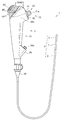
- FIG. 1 is a front view showing the appearance of the endoscope
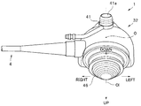
- FIG. 2 is a right side view showing the appearance of the endoscope
- FIG. 3 is a top view showing the appearance of the endoscope.
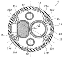
- FIG. 4 is an explanatory view showing an arrangement relationship between the wire pulling member and the cylinder
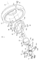
- FIG. 5 is a perspective view showing an arrangement relationship between the bending operation mechanism and the cylinder
- FIG. 6 is a perspective view showing an internal structure of the bending operation mechanism.
- FIG. 7 is an exploded perspective view showing the internal structure of the bending operation mechanism
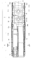
- FIG. 8 is a cross-sectional view showing the tip and the main part of the bending portion
- FIG. 9 shows the tip along the line IX-IX in FIG. 10
- FIG. 11 is a sectional view showing the curved portion along the line XI-XI in FIG. 8
- FIG. It is a top view which shows the principal part.
- the endoscope 1 of this embodiment shown in FIGS. 1 and 2 is an electronic endoscope for bronchi.
- the endoscope 1 is connected to an insertion portion 2 formed in an elongated tubular shape and a proximal end of the insertion portion 2.
- An operation unit 3 provided, a universal cord 4 that is an endoscope cable extending from the operation unit 3, and an endoscope connector 5 disposed at the distal end of the universal cord 4. Yes.
- the insertion portion 2 is constituted by a flexible tubular member in which a distal end portion 6, a bending portion 7, and a flexible tube portion 8 are connected in order from the distal end side.
- a metal tip hard portion 10 is provided in the tip portion 6, and the tip hard portion 10 includes a pair of an image pickup unit 11 including an image sensor such as a CCD or a CMOS.
- the light guide 12 and the treatment instrument insertion channel 13 are held.
- a cutting edge bending piece 20 having a substantially cylindrical shape is fitted on the proximal end side of the distal end hard portion 10, and the outer periphery of the cutting edge bending piece 20 is covered with a bending rubber 22.
- wire tip side fixing portions 21ur, 21ul, 21dr, 21dl are provided at four locations around the insertion axis O.
- the distal ends of the four bending wires 23ur, 23ul, 23dr, 23dl (hereinafter collectively referred to as the bending wire 23 as appropriate) inserted into the insertion portion 2 are respectively connected to the wire tip side fixing portions. It is fixed.
- the imaging unit 11 and the treatment instrument insertion channel 13, which are large members, are provided in the distal end hard portion 10 and the most advanced bending piece 20. Are arranged side by side (see FIGS. 8 and 9), and the light guides 12 are arranged in spaces formed vertically by these arrangements.
- the vertical and horizontal directions of the distal end portion 6 (insertion portion 2) are directions defined in association with vertical and horizontal directions of an image captured by the imaging unit 11, for example.
- each wire distal end side fixing portion has a predetermined angle around the insertion axis O with respect to the vertical and horizontal positions of the distal end portion 6. It is provided at the rotationally moved position. That is, for example, as shown in FIG. 9, the cutting edge bending piece 20 is at a position rotated about the insertion axis O within the range of 30 degrees to 60 degrees on the left and right with respect to the upward direction of the distal end portion 6.
- Each wire tip side fixing portion is provided.
- each bending wire 23 is routed at a position rotated around the insertion axis O by a predetermined angle with respect to the vertical and horizontal directions.
- the wire tip is located at each of the upper right, upper left, lower right, and lower left positions with respect to the insertion axis O.
- Side fixing portions 21ur, 21ul, 21dr, 21dl are provided.
- the wire tip side fixing portion 21ur located at the upper right of the most advanced bending piece 20 has a bending wire 23ur mainly contributing to the upward bending and the rightward bending of the bending portion 7. The tip end side (one end side) is held.
- the wire distal end side fixing portion 21ul located at the upper left of the most advanced bending piece 20 has a distal end side (one end side) of the bending wire 23ul that mainly contributes to the upward bending and the leftward bending of the bending portion 7. Is held.
- the wire distal end side fixing portion 21dr positioned at the lower right of the most advanced bending piece 20 has a distal end side (one end side) of the bending wire 23dr that mainly contributes to the downward bending and the rightward bending of the bending portion 7. ) Is held.
- the distal end side (one end side) of the bending wire 23dl that mainly contributes to the downward bending and the leftward bending of the bending portion 7 is provided in the wire distal end side fixing portion 21dl located at the lower left of the most advanced bending piece 20. Is held.
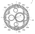
- the bending portion 7 can be actively bent in the entire circumferential direction around the insertion axis O including the up / down / left / right directions (UP-DOWN / RIGHT-LEFT) in response to an operation input from the operator or the like to the operation portion 3. It is configured. That is, the bending portion 7 of the present embodiment includes, for example, a pivot portion 25 a (see FIGS. 8 and 10) disposed in the vertical direction of the insertion portion 2 and a pivot portion 25 b ( 8 and 11), a bending piece set 24 in which a plurality of bending pieces 25 are connected in series is provided.
- a signal cable 11a, a light guide 12, and a treatment instrument insertion channel 13 extending from the imaging unit 11 are inserted in the same arrangement as in the distal end portion 6 as insertion objects. ing.
- the outer periphery of the bending piece set 24 is covered with a bending rubber 22 extending from the front end portion 6 side.
- the predetermined bending pieces 25 constituting the bending piece set 24 include wire guides 26ur, 26ul, 26dr, and 26dl (hereinafter, collectively referred to as wire guides 26 as appropriate) through which the bending wires 23 are inserted. Is formed. These wire guides 26 are provided at positions that are rotated by a predetermined angle around the insertion axis O with respect to the vertical and horizontal positions of the bending portion 7 in the same manner as the wire fixing portion 21 described above. That is, for example, as shown in FIGS. 10 and 11, the predetermined bending piece 25 is rotationally moved within the range of 30 to 60 degrees on the left and right sides around the insertion axis O with reference to the upward direction of the bending portion 7.
- Each wire guide 26 is provided at a position and a position rotated around the insertion axis O within a range of 30 degrees to 60 degrees on the left and right with respect to the downward direction of the bending portion 7.
- each bending wire 23 is routed at a position rotated around the insertion axis O in the vertical and horizontal directions.
- the flexible tube portion 8 is formed of a flexible tubular member that can bend passively.
- the signal cable 11a, the light guide 12, and the treatment instrument insertion channel 13 are inserted into the flexible tube portion 8 (all are not shown here).
- the operation unit 3 covers the proximal end of the flexible tube unit 8 and is connected to the flexible tube unit 8.
- the operation unit 3 is connected to the flexible tube unit 8 and is held by the user's hand. It is configured to include a possible grip portion 31 and an operation portion main body 32 that is connected to the proximal end side of the grip portion 31.
- the direction around the insertion axis O in the operation unit 3 is defined with reference to a state in which the user or the like grips the grip unit 31.
- the front-rear and left-right directions front surface, back surface, left and right side surfaces, etc. are defined with reference to the user or the like holding the part 31.
- the grip portion 31 is formed in a symmetrical shape with respect to the insertion axis O (center axis), and can be gripped by the user or the like in the same manner with either the left hand or the right hand. It has become.
- a treatment instrument insertion portion 35 is provided on the front surface on the distal end side of the grip portion 31.
- the treatment instrument insertion portion 35 includes a treatment instrument insertion port 35a for inserting various treatment instruments (not shown). Inside the operation section 3, the treatment instrument insertion channel 35 is communicated with the treatment instrument insertion port 35a via a branch member (not shown).
- a forceps plug (not shown), which is a lid member for closing the treatment tool insertion port 35a, is detachable from the treatment tool insertion portion 35.
- the operation unit main body 32 is configured by a hollow member having a substantially partial spherical shape that mainly bulges to the left and right sides and the front side on the proximal end side of the grip unit 31.
- An operation button group 40 for executing various functions of the endoscope 1 is disposed on the front side of the operation unit main body 32.
- a bending lever 45 for performing a bending operation on the bending portion 7 is disposed on the back side of the operation portion main body 32.
- the universal cord 4 extends from one side (for example, the left side) of the operation unit main body 32.
- the left and right shape of the operation unit main body 32 is a shape swelled symmetrically with respect to the insertion axis O, and the right and left side surfaces on the distal end side of the operation unit main body 32 are gripped by the grip portion 31.
- Guide recesses 32a for guiding the index finger of the person to the operation button group 40 are formed.
- the universal cord 4 reaches the operation unit 3 from the distal end 6 side through the inside of the insertion unit 2, and further passes various signal lines and the like extending from the operation unit 3 to the inside, and a light guide of a light source device (not shown).
- 12 is a composite cable through which a tube for air / water supply extending from an air / water supply device (not shown) is inserted.
- the endoscope connector 5 has an electric connector portion 5a to which a signal cable for connection with a video processor (not shown) of an external device is connected on a side surface portion, and is connected to a light source device that is an external device.
- the operation button group 40 includes, for example, a suction button 41 a as an operation button protruding from a suction valve 41 detachably attached to the operation unit main body 32 and various functions related to the endoscope 1. And two button switches 42 to which an arbitrary function can be assigned.
- the suction button 41a and the button switch 42 are arranged so as to be symmetrical on the front side of the operation unit main body 32.
- the suction button 41 a is disposed at the center in the left-right width direction of the operation unit main body 32 so as to overlap the insertion axis O.
- the two button switches 42 are arranged at positions that are symmetrical with respect to the insertion axis O on the tip side of the suction button 41a.
- a cylinder 43 as a button connecting member connected to the suction valve 41 is provided inside the operation portion main body 32.
- the cylinder 43 is detachably mountable with the suction valve 41, and is disposed at the center in the left-right width direction of the operation unit main body 32 so as to be superimposed on the insertion shaft O corresponding to the arrangement of the suction button 41a. .
- the bending lever 45 is configured by a lever whose free end side protruding from the operation section main body 32 can tilt at least in the up / down / left / right cross direction. More specifically, the bending lever 45 is configured by, for example, a joystick-type lever that can tilt in all directions including the vertical and horizontal directions.
- the bending lever 45 is disposed at a symmetrical position on the back side of the operation unit main body 32. That is, in the present embodiment, the bending lever 45 is disposed at the center in the left-right width direction of the operation unit main body 32 so as to overlap the insertion axis O.
- the left-right direction of the tilting operation is defined in the left-right width direction of the operation unit 3, which is a direction orthogonal to the insertion axis O, for example.
- a vertical direction is defined in a direction orthogonal to the width direction.
- the tilting direction of the bending lever 45 of the present embodiment is, for example, the tilting direction (left tilting direction) for curving the bending portion 7 leftward on the left side in FIG.
- the right side is a tilt direction (right tilt direction) for curving the curved portion 7 to the right side
- the lower side in FIG. 3 is the tilt direction (upward tilt direction) for curving the curved portion 7 upward
- the upper side is defined as a tilt direction (down tilt direction) for bending the bending portion 7 downward.
- a finger rest 46 capable of abutting the thumb of a user or the like is provided at the free end of the bending lever 45.
- a bending operation mechanism 50 is connected to the proximal end side (fixed end side) of the bending lever 45, and the bending lever 45 undergoes a pulling operation of each bending wire 23 by the bending operation mechanism 50.
- the bending portion 7 can be bent in any direction.
- the fixed end side of the bending lever 45 is supported by the bending operation mechanism 50 so as to be tiltable. For example, as shown in FIGS.
- the finger holding portion 46 provided on the free end side of the bending lever 45 may be formed in a substantially partial spherical shape centering on the tilting center C of the bending lever 45. As a result, the operability is improved because the finger rest is always the same distance from the center even if the bending lever moves.
- the bending operation mechanism 50 includes a housing 51 having a substantially cylindrical shape, a turning frame 52 pivotally supported in the housing 51, and a turning frame 52.
- a base member 53 that is pivotally supported (swingable) inside and a wire pulling member 54 that is fixed to the base member 53 are configured.
- the housing 51 is configured by a substantially cylindrical member, and axial holes 51 a facing each other are formed in the peripheral wall of the housing 51.
- the rotation frame 52 is constituted by a frame body having a substantially rectangular shape, for example.
- the rotating frame 52 has a pair of screw holes 52a facing each other in the center of both ends in the longitudinal direction, and a pair of shaft holes 52b facing each other in the center of both ends in the short direction. Yes. Then, the screw 55 inserted into each shaft hole 51 a of the housing 51 is screwed into each screw hole 52 a, so that the rotation frame 52 is pivotally supported with respect to the housing 51.
- the base member 53 is configured by a substantially cylindrical member.
- a fitting hole 53a is formed in the central portion of the base member 53, and the proximal end side of the bending lever 45 is connected to the fitting hole 53a by fitting.
- a pair of flat portions 53b facing each other are formed in the peripheral portion of the base member 53, and screw holes 53c (only one screw hole 53c is shown in FIG. 7) facing each other are formed in these flat portions 53b. It is installed.
- the base member 53 is pivotally supported with respect to the rotation frame 52 by screwing the screws 56 inserted into the shaft holes 52b of the rotation frame 52 into the screw holes 53c. .
- the base member 53 is supported by the housing 51 via the rotation frame 52 as described above, so that the bending lever 45 connected to the base member 53 has an arbitrary center around the tilt center C (see FIG. 2). It is possible to tilt in the direction.
- the wire pulling member 54 includes a pulling member main body 60 connected to the bending lever 45 through the base member 53, and four arms 61ur, 61ul, 61dr, 61dl (hereinafter referred to as these) extended from the pulling member main body 60. And collectively referred to as an arm 61 as appropriate) is formed by a plate-like member integrally formed.
- the pulling member main body 60 is fastened and fixed to the base member 53 via screws 57 so as to be orthogonal to the central axis Ol of the bending lever 45, for example.
- Each arm 61 extends from the pulling member main body 60 in four different directions.
- the arm 61ur mainly contributes to the upward bending and the bending to the right of the bending portion 7, and extends in a direction opposite to the corresponding bending operation direction. Yes. That is, for example, as shown in FIG. 4, the arm 61ur is in the direction opposite to the operation direction of the bending lever 45 for bending the bending portion 7 in the upward direction (UP), and the bending portion 7 is moved to the right.
- the bending lever 45 for bending in the direction (RIGHT) is extended in the direction opposite to the operation direction.
- the arm 61ul is mainly for contributing to the upward bending and the leftward bending of the bending portion 7, and extends in a direction opposite to the corresponding bending operation direction. That is, for example, as shown in FIG. 4, the arm 61ul is in a direction opposite to the operation direction of the bending lever 45 for bending the bending portion 7 upward (UP), and the bending portion 7 is moved to the left.
- the bending lever 45 for bending in the direction (LEFT) extends in the direction opposite to the operation direction.
- the arm 61dr is mainly for contributing to the downward bending and the rightward bending of the bending portion 7, and extends in a direction opposite to the corresponding bending operation direction. That is, for example, as shown in FIG. 4, the arm 61dr is in a direction opposite to the operation direction of the bending lever 45 for bending the bending portion 7 in the downward direction (DOWN), and the bending portion 7 is moved to the right.
- the bending lever 45 for bending in the direction (RIGHT) is extended in the direction opposite to the operation direction.
- the arm 61dl is mainly for contributing to the downward bending and the leftward bending of the bending portion 7, and extends in a direction opposite to the corresponding bending operation direction. That is, for example, as shown in FIG. 4, the arm 61dl is in the direction opposite to the operation direction of the bending lever 45 for bending the bending portion 7 in the downward direction (DOWN), and the bending portion 7 is moved to the left.
- the operation direction of the bending lever 45 for bending in the direction (LEFT) is extended in the reverse direction.
- wire proximal end fixing portions 62ur, 62ul, 62dr, 62dl are provided on the distal ends of the arms 61ur, 61ul, 61dl, 61dr, and the wire proximal end fixing portions 62ur, 62ul, 62dr, 62dl are The base end side (the other end side) of the corresponding bending wires 23ur, 23ul, 23dr, and 23dl is fixed (see FIG. 6).
- the proximal end side of the bending wire 23ur is fixed to the wire proximal end fixing portion 62ur provided on the arm 61ur.
- proximal end side of the bending wire 23ul is fixed to the wire proximal end fixing portion 62ul provided on the arm 61ul.
- proximal end side of the bending wire 23dr is fixed to the wire proximal end fixing portion 62dr provided in the arm 61dr.
- the proximal end side of the bending wire 23dl is fixed to the wire proximal end fixing portion 62dl provided on the arm 61dl.
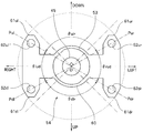
- the extension lengths of the arms 61ur, 61ul, 61dl, 61dr are set to be equal to each other.
- the arms 61ur, 61ul, 61dl, 61dr are set so that their extending ends are located on the same circumference centered on the central axis Ol of the bending lever 45 (FIG. 12). reference).
- the wire base end side fixing portions 62ur, 62ul, 62dr, and 62dl are also arranged on the same circumference with the central axis Ol of the bending lever 45 as the center.
- the bending operation mechanism 50 configured as described above is disposed in the operation portion main body 32 so as to face the cylinder 43 in the front-rear direction.
- the positions of the arms 61ur, 61ul, 61dl, 61dr are rotated around the central axis Ol of the bending lever 45 with respect to the vertical and horizontal tilt directions defined by the bending lever 45, respectively. Is arranged.
- the bending operation mechanism 50 is arranged in a state where the cylinder 43 faces between the two arms 61 ul and 61 ur of the wire pulling member 54.
- the wire pulling member 54 is configured so that at least one of the two arms 61ul and 61ur adjacent to the cylinder 43 has an angle ⁇ ulr formed by 90 degrees. Is also tilted in a wide angle direction.
- the arm 61ul of this embodiment has an angle ⁇ ulr formed with the arm 61ur wider than 90 degrees and an angle ⁇ lud formed with the arm 61dl of 90 degrees. It is tilted in a direction that makes the depression angle.
- the arm 61ur of the present embodiment is tilted in a direction in which the angle ⁇ ulr formed with the arm 61ul is wider than 90 degrees and the angle ⁇ rud formed with the arm 61dr is greater than 90 degrees. .
- ⁇ ulr is an angle ⁇ lud formed by a perpendicular line Pul connecting the wire proximal end fixing part 62ul and the central axis Ol of the bending lever 45 and a perpendicular line Pdl connecting the wire proximal end fixing part 62dl and the central axis Ol of the bending lever 45.
- the relationship of each wire proximal end fixing portion 62 is set so as to be wider.
- an angle ⁇ ulr formed by a perpendicular line Pur connecting the wire proximal end fixing portion 62ur and the central axis Ol of the bending lever 45 and a perpendicular line connecting the wire proximal end fixing portion 62ul and the central axis Ol of the bending lever 45 is ⁇ ulr. More than an angle ⁇ rud formed by a perpendicular line Pur connecting the wire proximal end fixing portion 62ur and the central axis Ol of the bending lever 45 and a perpendicular line Pdr connecting the wire proximal end fixing portion 62dr and the central axis Ol of the bending lever 45.
- fixed part 62 is set so that it may become large.
- the arm 61ul and the wire proximal end fixing portion 62ul are the first arm and the first wire proximal end fixing portion
- the arm 61ur and the wire proximal end fixing portion 62ur are the second arm and the second wire base.
- the arm 61dl and the wire base end side fixing portion 62dl correspond to the third arm and the third wire base end side fixing portion
- the arm 61dr and the wire base end side fixing portion 62dr correspond to the fourth end portion. It corresponds to the arm and the fourth wire proximal end fixing portion.
- the arm 61ur and the wire proximal end fixing portion 62ur are the first arm and the first wire proximal end fixing portion
- the arm 61ul and the wire proximal end fixing portion 62ul are the second arm and the second wire proximal end side.
- the arm 61dr and the wire base end side fixing portion 62dr correspond to the third arm and the third wire base end side fixing portion
- the arm 61dl and the wire base end side fixing portion 62dl correspond to the fourth arm and the arm 61dr. It corresponds to the fourth wire proximal end fixing portion.
- each arm 61 (and the wire proximal end fixing portion 62) is set to be symmetric with respect to the vertical and horizontal directions of the tilt defined in the bending lever 45. It is desirable.
- the arm 61ul (and the wire proximal end fixing portion 62ul), the arm 61ur (and the wire proximal end fixing portion 62ul), and the arm 61dl (and the wire proximal end fixing portion 62dl).
- the arm 61dr (and the wire proximal end fixing portion 62dr) are set so as to be symmetric (line symmetric) with respect to the vertical direction of the bending lever 45 (a line connecting the vertical direction).
- the arm 61ul (and the wire proximal end fixing portion 62ul), the arm 61dl (and the wire proximal end fixing portion 62dl), the arm 61ur (and the wire proximal end fixing portion 62ur), and the arm 61dr (and The wire base end side fixing portion 62dr) is set so as to be symmetric (axisymmetric) with respect to the left and right direction of the bending lever 45 (a line connecting the left and right directions).
- the bending portion 7 is appropriately bent with respect to the tilting operation of the bending lever 45. Therefore, it is desirable that the wire distal end fixing portions, the wire guides 26, and the like are also arranged in a relationship similar to the wire proximal end fixing portions 62.
- the two arms 61ur and 61dr are mainly used.
- the connected bending wires 23ur and 23dr are pulled.
- the bending portion 7 is bent to the left.
- the bending lever 45 when the user or the like grips the grip portion 31 of the operation unit 3 and tilts the bending lever 45 in the right tilting direction with the thumb of the gripped hand, the bending mainly connected to the two arms 61ul and 61dl is performed. The wires 23ul and 23dl are pulled. Thereby, the bending portion 7 is bent to the right side.
- the bending lever 45 when the user or the like grips the grip portion 31 of the operation unit 3 and tilts the bending lever 45 in the downward tilting direction with the thumb of the gripped hand, the bending mainly connected to the two arms 61dl and 61dr is performed. The wires 23dl and 23dr are pulled. As a result, the bending portion 7 is bent downward.
- the index finger or the like of the gripped hand is guided to the operation button group 40 along the guide recess 32 a, and the suction button 41 a or the like is pressed to operate the endoscope.
- Various functions such as a suction operation by 1 are executed.
- the operation unit 3 (gripping unit 31) has a symmetrical shape, and the suction button 41a and the bending lever 45 are arranged opposite to each other at the center in the left-right width direction of the operation unit 3 (operation unit body 32). Accordingly, the operation unit 3 can be gripped in the same manner with any of the left and right hands, and the suction button 41a and the bending lever 45 can be operated with the same operability.
- each arm 61 is arranged in a state in which it is rotated by a predetermined angle around the central axis Ol of the bending lever 45 with respect to the up / down / left / right tilt directions defined in the bending lever 45.
- the arm 61 and the like can be prevented from interfering with the cylinder 43.
- the angle ⁇ ulr formed between the arm 61ul and the arm 61ur facing the cylinder 43 is set to be a wider angle than 90 degrees, and the angle ⁇ lud formed between the arm 61ul and the arm 61dl is a depression angle larger than 90 degrees.
- the angle ⁇ rud formed by the arm 61ur and the arm 61dr can be a depression angle of more than 90 degrees, the interference between the wire pulling member 54 and the cylinder 43 can be avoided more accurately, and the operation unit 3
- the operation input units (such as the operation button group 40 including the suction button 41a) including the bending lever 45 can be arranged at appropriate positions without increasing the size of the operation lever.
- each arm 61 extends radially from the central axis Ol of the bending lever 45 .
- the arms 61ul, 61ur, 61dl, 61dr can be extended from the pulling member main body 60 in an “H shape”.
- the arm 61ul is inclined in a direction in which the angle ⁇ ulr formed with the arm 61ur is a wider angle than 90 degrees and the angle ⁇ lud formed with the arm 61dl is a depression angle more than 90 degrees.
- a pattern having a reverse angle relationship may be used.
- the arm 61ul may be tilted in a direction in which the angle ⁇ ulr formed with the arm 61ur is narrower than 90 degrees and the angle ⁇ lud formed with the arm 61dl is wider than 90 degrees. .
- the present invention is not limited to the embodiments described above, and various modifications and changes are possible, and these are also within the technical scope of the present invention.
- an example in which the present invention is applied to an endoscope for bronchi has been described.
- the present invention is not limited to this, and for example, for an endoscope for urology, etc. It is possible to apply.
- the tilting direction defined for the bending lever is not limited to the above-mentioned one, and the operation button is of course not limited to the suction button or the like.
Landscapes
- Physics & Mathematics (AREA)
- Health & Medical Sciences (AREA)
- Life Sciences & Earth Sciences (AREA)
- Optics & Photonics (AREA)
- Surgery (AREA)
- Biomedical Technology (AREA)
- Animal Behavior & Ethology (AREA)
- Radiology & Medical Imaging (AREA)
- Nuclear Medicine, Radiotherapy & Molecular Imaging (AREA)
- Engineering & Computer Science (AREA)
- Biophysics (AREA)
- Heart & Thoracic Surgery (AREA)
- Medical Informatics (AREA)
- Molecular Biology (AREA)
- Pathology (AREA)
- General Health & Medical Sciences (AREA)
- Public Health (AREA)
- Veterinary Medicine (AREA)
- Astronomy & Astrophysics (AREA)
- General Physics & Mathematics (AREA)
- Instruments For Viewing The Inside Of Hollow Bodies (AREA)
- Endoscopes (AREA)
Abstract
Selon la présente invention, un angle θulr formé entre un bras 61ul et un bras 60ur, qui font face à un cylindre (43), est réglé en vue d'être supérieur à 90 degrés, l'angle θlud formé entre le bras 61ul et un bras 61dl est réglé en vue d'être inférieur à 90 degrés, et l'angle θrud formé entre le bras 61ur et un bras 61dr est réglé en vue d'être inférieur à 90 degrés. En conséquence, l'interférence entre un élément de traction de câble (54) et le cylindre (43) est évitée avec plus de précision.
Priority Applications (1)
| Application Number | Priority Date | Filing Date | Title |
|---|---|---|---|
| JP2017539037A JPWO2017145431A1 (ja) | 2016-02-23 | 2016-09-30 | 内視鏡 |
Applications Claiming Priority (2)
| Application Number | Priority Date | Filing Date | Title |
|---|---|---|---|
| JP2016-032266 | 2016-02-23 | ||
| JP2016032266 | 2016-02-23 |
Publications (1)
| Publication Number | Publication Date |
|---|---|
| WO2017145431A1 true WO2017145431A1 (fr) | 2017-08-31 |
Family
ID=59686027
Family Applications (1)
| Application Number | Title | Priority Date | Filing Date |
|---|---|---|---|
| PCT/JP2016/079062 Ceased WO2017145431A1 (fr) | 2016-02-23 | 2016-09-30 | Endoscope |
Country Status (2)
| Country | Link |
|---|---|
| JP (1) | JPWO2017145431A1 (fr) |
| WO (1) | WO2017145431A1 (fr) |
Cited By (1)
| Publication number | Priority date | Publication date | Assignee | Title |
|---|---|---|---|---|
| CN114554926A (zh) * | 2019-10-28 | 2022-05-27 | 奥林巴斯株式会社 | 内窥镜 |
Citations (4)
| Publication number | Priority date | Publication date | Assignee | Title |
|---|---|---|---|---|
| WO2012117865A1 (fr) * | 2011-02-28 | 2012-09-07 | オリンパスメディカルシステムズ株式会社 | Dispositif médical doté d'une section de cambrure |
| WO2012117835A1 (fr) * | 2011-02-28 | 2012-09-07 | オリンパスメディカルシステムズ株式会社 | Endoscope et appareil médical |
| WO2013108486A1 (fr) * | 2012-01-16 | 2013-07-25 | オリンパスメディカルシステムズ株式会社 | Endoscope |
| WO2015174139A1 (fr) * | 2014-05-16 | 2015-11-19 | オリンパス株式会社 | Endoscope |
-
2016
- 2016-09-30 WO PCT/JP2016/079062 patent/WO2017145431A1/fr not_active Ceased
- 2016-09-30 JP JP2017539037A patent/JPWO2017145431A1/ja active Pending
Patent Citations (4)
| Publication number | Priority date | Publication date | Assignee | Title |
|---|---|---|---|---|
| WO2012117865A1 (fr) * | 2011-02-28 | 2012-09-07 | オリンパスメディカルシステムズ株式会社 | Dispositif médical doté d'une section de cambrure |
| WO2012117835A1 (fr) * | 2011-02-28 | 2012-09-07 | オリンパスメディカルシステムズ株式会社 | Endoscope et appareil médical |
| WO2013108486A1 (fr) * | 2012-01-16 | 2013-07-25 | オリンパスメディカルシステムズ株式会社 | Endoscope |
| WO2015174139A1 (fr) * | 2014-05-16 | 2015-11-19 | オリンパス株式会社 | Endoscope |
Cited By (4)
| Publication number | Priority date | Publication date | Assignee | Title |
|---|---|---|---|---|
| CN114554926A (zh) * | 2019-10-28 | 2022-05-27 | 奥林巴斯株式会社 | 内窥镜 |
| US20220240754A1 (en) * | 2019-10-28 | 2022-08-04 | Olympus Corporation | Endoscope, bending operation mechanism for endoscope, and operation portion for endoscope |
| CN114554926B (zh) * | 2019-10-28 | 2025-07-22 | 奥林巴斯株式会社 | 内窥镜、内窥镜的弯曲操作机构和内窥镜的操作部 |
| US12390093B2 (en) * | 2019-10-28 | 2025-08-19 | Olympus Corporation | Endoscope, bending operation mechanism for endoscope, and operation portion for endoscope |
Also Published As
| Publication number | Publication date |
|---|---|
| JPWO2017145431A1 (ja) | 2018-03-01 |
Similar Documents
| Publication | Publication Date | Title |
|---|---|---|
| JP5930255B2 (ja) | 内視鏡 | |
| JP6301014B2 (ja) | 湾曲操作装置および内視鏡 | |
| JP6506890B1 (ja) | 内視鏡の操作ユニット | |
| JP6076556B1 (ja) | 湾曲操作装置及び内視鏡 | |
| JP6081684B1 (ja) | 内視鏡 | |
| JP6116777B1 (ja) | 湾曲操作装置および内視鏡 | |
| JP6017742B1 (ja) | 内視鏡操作部および内視鏡 | |
| JP6465447B2 (ja) | 内視鏡の製造方法 | |
| JP6062138B1 (ja) | 内視鏡 | |
| CN114502056B (zh) | 内窥镜的弯曲操作机构和内窥镜 | |
| WO2017145431A1 (fr) | Endoscope | |
| JP6250232B1 (ja) | 湾曲操作装置及びこれを適用した内視鏡 |
Legal Events
| Date | Code | Title | Description |
|---|---|---|---|
| ENP | Entry into the national phase |
Ref document number: 2017539037 Country of ref document: JP Kind code of ref document: A |
|
| NENP | Non-entry into the national phase |
Ref country code: DE |
|
| 121 | Ep: the epo has been informed by wipo that ep was designated in this application |
Ref document number: 16891587 Country of ref document: EP Kind code of ref document: A1 |
|
| 122 | Ep: pct application non-entry in european phase |
Ref document number: 16891587 Country of ref document: EP Kind code of ref document: A1 |