WO2017145440A1 - Amortisseur de vibrations de torsion pour arbre tournant - Google Patents
Amortisseur de vibrations de torsion pour arbre tournant Download PDFInfo
- Publication number
- WO2017145440A1 WO2017145440A1 PCT/JP2016/081716 JP2016081716W WO2017145440A1 WO 2017145440 A1 WO2017145440 A1 WO 2017145440A1 JP 2016081716 W JP2016081716 W JP 2016081716W WO 2017145440 A1 WO2017145440 A1 WO 2017145440A1
- Authority
- WO
- WIPO (PCT)
- Prior art keywords
- rotating shaft
- torsional vibration
- bearing
- gear
- vibration
- Prior art date
- Legal status (The legal status is an assumption and is not a legal conclusion. Google has not performed a legal analysis and makes no representation as to the accuracy of the status listed.)
- Ceased
Links
Images


Classifications
-
- F—MECHANICAL ENGINEERING; LIGHTING; HEATING; WEAPONS; BLASTING
- F16—ENGINEERING ELEMENTS AND UNITS; GENERAL MEASURES FOR PRODUCING AND MAINTAINING EFFECTIVE FUNCTIONING OF MACHINES OR INSTALLATIONS; THERMAL INSULATION IN GENERAL
- F16C—SHAFTS; FLEXIBLE SHAFTS; ELEMENTS OR CRANKSHAFT MECHANISMS; ROTARY BODIES OTHER THAN GEARING ELEMENTS; BEARINGS
- F16C27/00—Elastic or yielding bearings or bearing supports, for exclusively rotary movement
- F16C27/06—Elastic or yielding bearings or bearing supports, for exclusively rotary movement by means of parts of rubber or like materials
-
- F—MECHANICAL ENGINEERING; LIGHTING; HEATING; WEAPONS; BLASTING
- F16—ENGINEERING ELEMENTS AND UNITS; GENERAL MEASURES FOR PRODUCING AND MAINTAINING EFFECTIVE FUNCTIONING OF MACHINES OR INSTALLATIONS; THERMAL INSULATION IN GENERAL
- F16F—SPRINGS; SHOCK-ABSORBERS; MEANS FOR DAMPING VIBRATION
- F16F15/00—Suppression of vibrations in systems; Means or arrangements for avoiding or reducing out-of-balance forces, e.g. due to motion
- F16F15/10—Suppression of vibrations in rotating systems by making use of members moving with the system
-
- F—MECHANICAL ENGINEERING; LIGHTING; HEATING; WEAPONS; BLASTING
- F16—ENGINEERING ELEMENTS AND UNITS; GENERAL MEASURES FOR PRODUCING AND MAINTAINING EFFECTIVE FUNCTIONING OF MACHINES OR INSTALLATIONS; THERMAL INSULATION IN GENERAL
- F16F—SPRINGS; SHOCK-ABSORBERS; MEANS FOR DAMPING VIBRATION
- F16F15/00—Suppression of vibrations in systems; Means or arrangements for avoiding or reducing out-of-balance forces, e.g. due to motion
- F16F15/20—Suppression of vibrations of rotating systems by favourable grouping or relative arrangements of the moving members of the system or systems
-
- F—MECHANICAL ENGINEERING; LIGHTING; HEATING; WEAPONS; BLASTING
- F16—ENGINEERING ELEMENTS AND UNITS; GENERAL MEASURES FOR PRODUCING AND MAINTAINING EFFECTIVE FUNCTIONING OF MACHINES OR INSTALLATIONS; THERMAL INSULATION IN GENERAL
- F16F—SPRINGS; SHOCK-ABSORBERS; MEANS FOR DAMPING VIBRATION
- F16F15/00—Suppression of vibrations in systems; Means or arrangements for avoiding or reducing out-of-balance forces, e.g. due to motion
- F16F15/22—Compensation of inertia forces
Definitions
- the present invention relates to a torsional vibration damper of a rotating shaft, and is useful when applied to a rotary drive machine that generates torque pulsation, such as a motor, a turbine, or a compressor.
- FIG. 4 is a cross-sectional view showing an example of a torsional vibration damper of a rotating shaft according to the prior art.
- the torsional vibration damper includes a cylindrical member 02 fitted to the rotation shaft 01 and a ring-shaped mass member fitted to the cylindrical member 02 via a ring-shaped elastic member 03.
- the cylindrical member 02, the elastic member 03, and the mass member 04 are formed so as to be concentric with the axis of the rotating shaft 01.
- the mass member 04 is supported on the rotating shaft 01 via the elastic member 03 such as rubber, and a vibration system that vibrates in the circumferential direction is formed.
- the vibration damper the torsional vibration generated in the rotating shaft 01 due to the vibration caused by the vibration system is canceled and suppressed.
- the vibration system for canceling the torsional vibration rotates together with the rotating shaft 01 on the rotating shaft 01. And so on. Further, the weight of the rotating shaft 01 itself increases, leading to an increase in size. Furthermore, since the mass portion 04 having a large weight is attached to the rotation shaft 01 via the elastic member 03, the center of the mass portion 04 is easily decentered with respect to the center of the rotation shaft 01. Coupled with the fact that the mass member 04 is a heavy object, the whirling vibration is further increased.
- the present invention can satisfactorily suppress torsional vibration generated in the rotary shaft without being directly mounted on the rotary shaft to be damped, and can also achieve downsizing and weight reduction.
- An object of the present invention is to provide a torsional vibration damper.
- the present invention for achieving the above object
- the bearing is a torsional vibration damper for a rotating shaft, wherein the bearing is formed so as to be able to absorb vibrations in a radial direction of the associated rotating shaft.
- the torsional vibration of the main rotating shaft transmitted to the associated rotating shaft via the one and other gears is converted into radial vibration of the associated rotating shaft.
- the bearing of the associated rotating shaft supports the associated rotating shaft so as to absorb the vibration in the radial direction
- the vibration in the radial direction of the associated rotating shaft is absorbed by the bearing and consumed as heat. Is done.
- the associated rotating shaft is configured such that the natural frequency of vibration in the radial direction matches the torsional natural frequency of the main rotating shaft. This is because the torsional vibration of the main rotating shaft is most efficiently converted into the radial vibration of the associated rotating shaft.
- the one gear is formed in a plurality of positions dispersed in a plurality of positions in the axial direction of the main rotary shaft, the other rotary shaft is formed with other gears respectively meshed with the one gear, Both end portions of the associated rotating shaft can be supported by the bearings.
- the torsional vibration of each mode can be controlled in an appropriate manner corresponding to the torsional vibration of different modes generated at each position in the axial direction of the main rotating shaft.
- the bearing can be formed of an oil bearing.
- the bearing includes a rolling bearing, a cylindrical damping member, and a ring-shaped elastic member, and the outer ring of the rolling bearing is connected to the inner peripheral surface of the fixed portion via the damping member and the elastic member. Can be fixed to. In these cases, the presence of the oil film or the presence of the elastic member can absorb the vibration in the radial direction of the associated rotation shaft in any case.
- the torsional vibration generated in the main rotating shaft is transmitted to the associated rotating shaft via one and the other gears. Then, the torsional vibration transmitted to the associated rotating shaft is converted into radial vibration of the associated rotating shaft.
- the bearing of the associated rotating shaft supports the associated rotating shaft so as to absorb the vibration in the radial direction
- the vibration in the radial direction of the associated rotating shaft is absorbed by the bearing and consumed as heat. Is done.
- the torsional vibration of the main rotating shaft is absorbed and suppressed by the accompanying rotating shaft system including the other gear rotating around the axis parallel to the main rotating shaft, the accompanying rotating shaft, and the bearing.
- the associated rotating shaft has an independent axis that is parallel to the main rotating shaft, and the accompanying rotating shaft system does not rotate integrally on the main rotating shaft.
- the main rotating shaft and the accompanying rotating shaft may be considered as separate objects, and the main rotating shaft itself does not increase in size and does not cause unbalanced vibration at the same time.
- the restriction element of the arrangement position on the main rotational axis of the torsional vibration damper according to the present invention is also relaxed, and the degree of freedom of the arrangement position is increased.
- a plurality of torsional vibration dampers according to the present invention can be effectively distributed in a plurality of torsional vibration modes by dispersively installing them at a plurality of locations on the main rotation shaft.
- FIG. 1A and 1B are views showing a torsional vibration damper according to an embodiment of the present invention
- FIG. 1A is a side view thereof
- FIG. 1B is a cross-sectional view taken along line AA of FIG. 1A
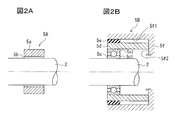
- 2A and 2B are sectional views showing an example of the configuration of the bearing portion in FIG. 1A extracted and enlarged.
- FIG. 3 is a side view showing a torsional vibration damper according to another embodiment of the present invention.
- FIG. 4 is a sectional view showing a torsional vibration damper according to the prior art.
- FIGS. 1A and 1B are views showing a torsional vibration damper according to an embodiment of the present invention
- FIG. 1A is a side view thereof
- FIG. 1B is a cross-sectional view taken along line AA of FIG. 1A.
- a gear 3 one gear
- the position in the axial direction of the main rotating shaft 1 forming the gear 3 is determined in advance by specifying the position where the torsional vibration to be reduced significantly occurs by calculation or the like.
- a gear (the other gear) 4 that meshes with the gear 3 is formed on the outer peripheral surface of the associated rotary shaft 2.
- the associated rotary shaft 2 is rotatably supported by bearings 5 at both ends so that the axis is parallel to the main rotary shaft 1.
- the bearing 5 has a structure capable of absorbing the vibration in the radial direction. The specific structure will be described later in detail based on FIGS. 2A and 2B.
- the torsional vibration generated in the main rotating shaft 1 is transmitted to the associated rotating shaft 2 via the gears 3 and 4.
- the associated rotary shaft 2 rotates with the main rotary shaft 1 and vibrates in the radial direction thereof.
- Such vibration is referred to as “lateral vibration”.
- the bearing 5 supporting the associated rotating shaft 2 is configured to absorb lateral vibration. Therefore, the lateral vibration of the associated rotating shaft system formed by the gear 4, the associated rotating shaft 2, and the member on the associated rotating shaft 2 side of the bearing 5 is coupled to the torsional vibration of the main rotating shaft 1, so that the bearing 5 Due to this damping function, lateral vibration of the associated rotating shaft system is suppressed, and torsional vibration of the main rotating shaft 1 is suppressed.
- a torsional vibration damper generated in the main rotating shaft 1 is configured by an accompanying rotating shaft system including the accompanying rotating shaft 2, the gear 4 and the bearing 5.
- the natural frequency of the lateral vibration of the associated rotary shaft 2 is configured to match the torsional natural frequency of the main rotary shaft 1. It is not essential to match the natural frequencies in this way, but if they are matched, the energy of torsional vibration can be converted to lateral vibration of the largest energy, and the vibration damping effect of torsional vibration is also remarkable. It will be something.
- the torsional vibration generated in the main rotating shaft 1 and the lateral vibration of the associated rotating shaft system are coupled, so that the energy of the torsional vibration is consumed by the damping function of the bearing 5 and heat. Become.
- torsional vibration can be suppressed.
- the energy of the torsional vibration is most efficiently transmitted through the associated rotating shaft 2. It can be absorbed by the bearing 5.
- FIG. 2A and 2B are cross-sectional views showing two examples extracted and enlarged as a configuration example of the portion of the bearing 5 in FIG. 1A.
- An oil bearing 5A shown in FIG. 2A is a kind of sliding bearing, and a ring-shaped sleeve 5a is fitted into the associated rotating shaft 2 via an oil film 5b.
- the drag due to the viscosity of the oil film 5b acts to suppress the lateral vibration.
- heat due to the viscous resistance of the oil film 5b is generated in the oil film 5b by lateral vibration.
- the energy of the lateral vibration is consumed as heat. Therefore, when applied to the bearing 5 in the above embodiment, the torsional vibration of the main rotary shaft 1 can be satisfactorily suppressed.
- a bearing 5B shown in FIG. 2B includes a concentric rolling bearing 5c, a cylindrical damping member 5d, and a ring-shaped elastic member 5e.
- the rolling bearing 5c in which the associated rotating shaft 2 is fitted through the inner ring 5c1 is fitted into the inner circumferential surface of the damping member 5d through the outer ring 5c2, and the damping member 5d is fitted to the outer circumferential surface thereof. And is fitted into the elastic member 5e.
- the bearing 5B is fitted and fixed to the fixing portion 5f (specifically, the inner peripheral surface 5f1 of the fixing portion 5f) via the outermost elastic member 5e.
- the damping member 5d is also directly fixed to the fixing portion 5f with its end abutting against the end surface 5f2 intersecting the inner peripheral surface 5f1 of the fixing portion 5f.
- a viscoelastic damper is formed by the damping member 5d and the elastic member 5e, and functions to absorb and suppress the lateral vibration.
- FIG. 3 is a side view showing a torsional vibration damper according to another embodiment of the present invention.
- one gear 3, 13, 23 is dispersed in a plurality of locations (three in the example shown in FIG. 3) in the axial direction of the main rotating shaft 1.
- a plurality (three in the example shown in FIG. 3) are formed.
- the other gears 4, 14, and 24 that mesh with the gears 3, 13, and 23 are disposed corresponding to the gears 3, 13, and 23.
- Each gear 4, 14, 24 is rotatably supported at both ends by bearings 5, 15, 25.
- the bearings 15 and 25 have a structure capable of absorbing vibrations in the respective radial directions.
- the torsional vibrations of the respective modes can be individually controlled corresponding to the torsional vibrations of the different modes generated at the respective positions in the axial direction of the main rotary shaft 1. More specifically, the longer the main rotating shaft 1 is, the more torsional vibrations occur in different vibration modes at different positions in the axial direction. According to the present embodiment, even in this case, the torsional vibration in each vibration mode can be effectively converted into lateral vibration, and each lateral vibration can be appropriately damped by the bearings 5, 15, and 25.
- the natural frequency of the lateral vibration of each of the associated rotating shafts 2, 12, 22 is configured to match the torsional natural frequency at the position where the gears 3, 13, 23 are formed on the main rotating shaft 1. The torsional vibration of each vibration mode can be damped most efficiently.
Landscapes
- Engineering & Computer Science (AREA)
- General Engineering & Computer Science (AREA)
- Mechanical Engineering (AREA)
- Physics & Mathematics (AREA)
- Acoustics & Sound (AREA)
- Aviation & Aerospace Engineering (AREA)
- Vibration Prevention Devices (AREA)
- Support Of The Bearing (AREA)
Abstract
L'invention concerne un amortisseur de vibrations de torsion pour un arbre tournant avec lequel les vibrations de torsion se produisant dans l'arbre tournant peuvent être correctement amorties sans que l'amortisseur soit directement installé sur un arbre tournant qui est amorti et avec lequel il est possible de réduire la taille et le poids. L'amortisseur comprend : un engrenage (3) relié à une charge et formé dans la direction circonférentielle d'un arbre tournant principal dans lequel se produisent des vibrations de torsion ; et un arbre tournant (2) associé, dont les deux extrémités sont supportées rotatives par des paliers (5) de sorte que la ligne axiale est parallèle à l'arbre tournant principal (1), et dans la direction circonférentielle duquel est formé l'autre engrenage (4) destiné à coopérer avec l'engrenage (3). Les paliers (5) sont formés de manière à pouvoir absorber les vibrations de direction radiale de l'arbre tournant (2) associé.
Applications Claiming Priority (2)
| Application Number | Priority Date | Filing Date | Title |
|---|---|---|---|
| JP2016035858A JP2017150639A (ja) | 2016-02-26 | 2016-02-26 | 回転軸のねじり振動ダンパ |
| JP2016-035858 | 2016-02-26 |
Publications (1)
| Publication Number | Publication Date |
|---|---|
| WO2017145440A1 true WO2017145440A1 (fr) | 2017-08-31 |
Family
ID=59684984
Family Applications (1)
| Application Number | Title | Priority Date | Filing Date |
|---|---|---|---|
| PCT/JP2016/081716 Ceased WO2017145440A1 (fr) | 2016-02-26 | 2016-10-26 | Amortisseur de vibrations de torsion pour arbre tournant |
Country Status (2)
| Country | Link |
|---|---|
| JP (1) | JP2017150639A (fr) |
| WO (1) | WO2017145440A1 (fr) |
Citations (6)
| Publication number | Priority date | Publication date | Assignee | Title |
|---|---|---|---|---|
| JPS4956302U (fr) * | 1972-08-17 | 1974-05-18 | ||
| JPH0219950U (fr) * | 1988-07-15 | 1990-02-09 | ||
| JPH03107613A (ja) * | 1989-09-21 | 1991-05-08 | Nippon Seiko Kk | 防振型転がり軸受 |
| JPH10306844A (ja) * | 1997-05-02 | 1998-11-17 | Mitsubishi Jidosha Tekunometaru Kk | 可変速度型ダンパ |
| JP2000249191A (ja) * | 1999-02-26 | 2000-09-12 | Meta Motoren & Energ Technik Gmbh | 往復動内燃機関におけるマスバランスおよび/またはモーメントバランスのための装置 |
| JP2008202726A (ja) * | 2007-02-21 | 2008-09-04 | Otics Corp | レシプロエンジン用のバランサ機構 |
-
2016
- 2016-02-26 JP JP2016035858A patent/JP2017150639A/ja active Pending
- 2016-10-26 WO PCT/JP2016/081716 patent/WO2017145440A1/fr not_active Ceased
Patent Citations (6)
| Publication number | Priority date | Publication date | Assignee | Title |
|---|---|---|---|---|
| JPS4956302U (fr) * | 1972-08-17 | 1974-05-18 | ||
| JPH0219950U (fr) * | 1988-07-15 | 1990-02-09 | ||
| JPH03107613A (ja) * | 1989-09-21 | 1991-05-08 | Nippon Seiko Kk | 防振型転がり軸受 |
| JPH10306844A (ja) * | 1997-05-02 | 1998-11-17 | Mitsubishi Jidosha Tekunometaru Kk | 可変速度型ダンパ |
| JP2000249191A (ja) * | 1999-02-26 | 2000-09-12 | Meta Motoren & Energ Technik Gmbh | 往復動内燃機関におけるマスバランスおよび/またはモーメントバランスのための装置 |
| JP2008202726A (ja) * | 2007-02-21 | 2008-09-04 | Otics Corp | レシプロエンジン用のバランサ機構 |
Also Published As
| Publication number | Publication date |
|---|---|
| JP2017150639A (ja) | 2017-08-31 |
Similar Documents
| Publication | Publication Date | Title |
|---|---|---|
| US9115765B2 (en) | Torque transmission device for a motor vehicle | |
| JP6252686B2 (ja) | ダンパ装置 | |
| US9068626B2 (en) | Balancer device of internal combustion engine | |
| US20140352290A1 (en) | Torsional vibration damping device | |
| US10927891B2 (en) | Bearing arrangement | |
| WO2012043302A1 (fr) | Dispositif de transmission à fluide | |
| US20150316135A1 (en) | Gearwheel for a backlash-free transmission stage and transmission stage equipped therewith | |
| WO2016208767A1 (fr) | Dispositif amortisseur | |
| CN103573911B (zh) | 用于飞轮减振的设备 | |
| KR101714208B1 (ko) | 개별 회전 관성질량을 갖춘 토셔널 댐퍼와 이를 적용한 크랭크샤프트 | |
| CN103851127B (zh) | 用于飞轮的阻尼的装置 | |
| BR102018004448A2 (pt) | dispositivo de amortecimento de vibração torcional | |
| JPWO2017131229A1 (ja) | ダンパ装置 | |
| JP2016118249A (ja) | 車両用電動機のロータ軸の支持構造 | |
| JP5787003B2 (ja) | 流体伝動装置 | |
| JP2013139789A (ja) | インペラチューブ組立体 | |
| CN110360300A (zh) | 皮带盘去耦器以及具有相应的皮带盘去耦器的辅助设备驱动器和驱动发动机 | |
| JP6584646B2 (ja) | 軸受装置を備えた回転振動ダンパ | |
| WO2017145440A1 (fr) | Amortisseur de vibrations de torsion pour arbre tournant | |
| WO2016167013A1 (fr) | Absorbeur dynamique de vibrations | |
| JP2010014273A (ja) | 回転振動ダンパ | |
| JP2015152159A (ja) | ダイナミックダンパ及び動力伝達軸の回転変動抑制装置 | |
| EP2949963B1 (fr) | Appareil amortisseur | |
| JP2019019918A (ja) | 減衰機構 | |
| JP6981182B2 (ja) | 動力伝達装置 |
Legal Events
| Date | Code | Title | Description |
|---|---|---|---|
| NENP | Non-entry into the national phase |
Ref country code: DE |
|
| 121 | Ep: the epo has been informed by wipo that ep was designated in this application |
Ref document number: 16891596 Country of ref document: EP Kind code of ref document: A1 |
|
| 122 | Ep: pct application non-entry in european phase |
Ref document number: 16891596 Country of ref document: EP Kind code of ref document: A1 |