WO2017145501A1 - Dispositif de porte pour ascenseur - Google Patents
Dispositif de porte pour ascenseur Download PDFInfo
- Publication number
- WO2017145501A1 WO2017145501A1 PCT/JP2016/087442 JP2016087442W WO2017145501A1 WO 2017145501 A1 WO2017145501 A1 WO 2017145501A1 JP 2016087442 W JP2016087442 W JP 2016087442W WO 2017145501 A1 WO2017145501 A1 WO 2017145501A1
- Authority
- WO
- WIPO (PCT)
- Prior art keywords
- door
- car
- landing
- engagement
- car door
- Prior art date
- Legal status (The legal status is an assumption and is not a legal conclusion. Google has not performed a legal analysis and makes no representation as to the accuracy of the status listed.)
- Ceased
Links
Images




Classifications
-
- B—PERFORMING OPERATIONS; TRANSPORTING
- B66—HOISTING; LIFTING; HAULING
- B66B—ELEVATORS; ESCALATORS OR MOVING WALKWAYS
- B66B13/00—Doors, gates, or other apparatus controlling access to, or exit from, cages or lift well landings
- B66B13/02—Door or gate operation
- B66B13/12—Arrangements for effecting simultaneous opening or closing of cage and landing doors
-
- B—PERFORMING OPERATIONS; TRANSPORTING
- B66—HOISTING; LIFTING; HAULING
- B66B—ELEVATORS; ESCALATORS OR MOVING WALKWAYS
- B66B13/00—Doors, gates, or other apparatus controlling access to, or exit from, cages or lift well landings
- B66B13/02—Door or gate operation
- B66B13/14—Control systems or devices
Definitions
- the present invention relates to a door device that opens and closes an elevator door panel, and more particularly to an elevator door device having a configuration for smoothly operating a landing door.
- the car-engaging vane grips the belt that transmits the driving force of the motor, and when the car door is driven, the other car-engaging vane moves in conjunction with the amount of movement of one car-engaging vane.
- a conventional technique for holding and opening and closing see, for example, Patent Document 1).
- the prior art has the following problems.
- the motor as a drive source is attached only to the car door side, and the landing door is connected to the car door by an engagement device, thereby driving the car door and the landing door. Open and close the door.
- the engagement device is composed of a car-side car-engaging vane and a landing-side landing roller, and an engagement gap and an engagement gap so that the two parts do not come into contact with each other when the elevator car is raised or lowered.
- a gap that is referred to is provided. This engagement gap is periodically checked during installation and maintenance so as to be maintained within proper specifications.
- the motor when the door is opened after the car is landed, the motor generates a driving force, and after driving the car door, the car door and the landing door are connected via the engaging device.
- the car engagement vanes on the car side may not be in a state of completely gripping and pinching the landing roller, and there may be a gap.
- Patent Document 1 has a structure in which when one car engaging vane moves when the car door is opened, the other car engaging vane is operated according to the amount of movement. By having such a structure, when the predetermined amount of movement is reached, a configuration in which the landing roller is completely gripped by both the car engagement vanes is realized.
- the value of the engagement gap varies from elevator to elevator and from floor to floor. For this reason, the predetermined movement amount must be assumed to be the maximum value of the expected engagement gap. Therefore, when the car door and the landing door are connected, only one car engaging vane is in contact with the landing roller, and there is a gap between the other car engaging vane and the landing roller. There is a problem that the operations are not always integrated.
- the present invention has been made to solve the above-described problems, and an object of the present invention is to provide an elevator door device capable of smoothly operating a landing door even when a disturbance is applied to the landing door.
- An elevator door device includes a door panel including a car door panel that opens and closes an entrance and a landing door panel, a motor that outputs driving force for opening and closing the door panel, and an elevator car landing on a landing floor.
- An elevator door device including an engagement mechanism unit that engages the car door panel and the landing door panel when the car door panel and the landing door panel are interlocked to perform an opening and closing operation in a state in which the engagement door is engaged.
- the car door panel and the landing door panel are connected in synchronization with the timing when the car door panel and the landing door panel are brought into contact with each other when the door panel is opened and closed in the landing state. In all opening and closing positions where the door panel opens and closes by the driving force generated in the door closing direction, it is connected It is intended to maintain.
- the operation of the car door and the landing door is integrated in the door opening and closing after the car is landed, and the connection between the car door and the landing door is always maintained at all the door opening and closing positions.
- FIG. 1 is an overall schematic diagram showing an elevator car door drive device according to Embodiment 1 of the present invention. BRIEF DESCRIPTION OF THE DRAWINGS
- FIG. 1 is an overall schematic diagram illustrating an elevator landing door drive device according to a first embodiment of the present invention. It is a schematic diagram of the engagement gap by Embodiment 1 of this invention. It is a block diagram of the door apparatus before the door opening start by Embodiment 1 of this invention. It is a block diagram of the door apparatus just before the door opening engagement by Embodiment 1 of this invention. It is a block diagram of the door apparatus at the time of door opening engagement by Embodiment 1 of this invention.
- Embodiment 1 of this invention It is a figure for demonstrating the smoothness degree of the door opening operation
- FIG. 1 is an overall schematic diagram showing an elevator car door drive apparatus according to Embodiment 1 of the present invention.
- a hanging hand 2 is provided at the upper end of the car-side door panel 1 that opens and closes the doorway.
- a girder 3 On the upper edge of the entrance / exit, there is provided a girder 3 whose longitudinal direction is arranged in the horizontal direction.
- the door panel 1 is comprised by the two door panels 1A and 1B is illustrated.
- the girder 3 is provided with a guide rail 4 arranged in the longitudinal horizontal direction, and the hanger roller 5 provided on the hanger 2 moves along the rail 4 so that the hanger 2 moves horizontally, that is, a door panel. Guide 1 open / close movement. Similarly, an up thrust roller 11 provided on the suspension 2 is attached below the rail 4 to prevent the hanger roller 5 from falling off the rail 4.
- pulleys 6A and 6B are pivoted apart from each other, and an endless belt 7 is stretched around the pulleys 6A and 6B.
- One end of the belt grip 8 is connected to the belt 7 and the other end is connected to the car engagement vane 12, and the motor 9 drives the pulley 6A.
- the belt 7 is a conductive belt, and generally a toothed belt or a V-belt is used.
- the car engagement vane 12 is connected to the door panel 1A by a mechanism described later, and the driving force is transmitted to the other door panel 1B via an interlocking rope or a belt.
- the door panels 1A and 1B by operating the door panels 1A and 1B in the same direction, the door is opened and closed by the urging of the motor 9.
- the configuration shown in FIG. 1 is a single-open door mechanism, but in a double-open door, the door panel 1A to which the driving force from the car engagement vane 12 is transmitted and the other door panel 1B are connected to an interlocking rope or belt.
- the doorway may be opened and closed by operating in opposite directions.
- the magnitude of the speed of the door panel 1B is half that of the door panel 1A. In the case of the double door, although the direction is different, the magnitude of the speed is equal between the door panels 1A and 1B. It becomes.
- the motor 9 when the elevator car is landed and the floor heights of the car door and the landing door are approximately the same, if the motor 9 is energized, the car engagement vane 12 and the landing roller 13 are brought into contact with and engaged with each other. Thus, the driving force of the car door can be transmitted to the landing door.
- the landing roller 13 is illustrated in FIG. 2 described later.
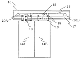
- FIG. 2 is an overall schematic diagram showing the elevator landing door drive apparatus according to Embodiment 1 of the present invention.
- a suspension 15 is provided at the upper end of the door panel 14 on the landing side that opens and closes the doorway shown in FIG.
- a girder 16 At the upper edge of the entrance / exit, there is provided a girder 16 whose length is arranged in the horizontal direction.
- the girder 16 is provided with a landing door guide rail 17 so as to be arranged in the longitudinal horizontal direction. Further, the hanger roller 18 provided on the hanger 15 moves along the rail 17 to guide the horizontal movement of the hanger 15, that is, the opening / closing movement of the door panel 14.
- an up thrust roller 19 provided on the suspension 15 is attached below the rail 17 to prevent the hanger roller 18 from falling off the rail 17.
- Pulleys 20A and 29B are pivotally attached to the spar 16 apart from each other, and an interlocking rope 21 is stretched around both pulleys 20A and 20B.
- the suspension of the door panel 14A is connected to the interlocking rope 21.
- the interlocking rope 21 may be a belt other than the rope.
- the driving force is transmitted to the other door panel 14B and the door panel 14A via another interlocking rope or belt different from the interlocking rope 21.
- the door panels 14A and 14B operate in the same direction. Become.
- FIG. 2 The configuration shown in FIG. 2 is a one-sided door mechanism, but in a double door, the door panel 14A and the other door panel 14B are moved in opposite directions via the interlocking rope 21 to open and close the doorway. do it.
- the driving force of the motor 9 acting on the landing roller 13 is transmitted to the door panels 14A and 14B, so that the landing door 14 can be opened and closed by the urging of the motor 9.
- the landing door 14 is provided with a door closing force generating mechanism using a weight or a spring (not shown) so that the landing door 14 is automatically fully closed even when the landing door 14 is opened when the car is not landing. In addition, a mechanical external force is applied.
- the car door 1 is also mechanically closed so that the infant does not open the car door 1 and fall into the hoistway.
- a force generation mechanism is provided. Then, a mechanical door opening force generation mechanism is attached to the car door 1 so that the motor door does not have a driving force when fully opened, or the car door 1 can be kept fully open only with a small driving force.
- FIG. 3 is a schematic diagram of the engagement gap according to the first embodiment of the present invention. Since the elevator car moves up and down in a hoistway (not shown), the car engaging vanes 12 attached to the car door panel 1 shown in FIG. 3 move in the hoistway. On the other hand, the landing roller 13 protrudes into the hoistway. Therefore, when the elevator car ascends and descends, if it comes into contact with the car-side equipment, in particular, the car engagement vane 12, both of them are damaged.
- the engagement gap 22 that is the distance between the car engagement vane 12 and the landing roller 13 is kept constant. It is necessary to adjust the mechanical system. If the engagement gap 22 is short, there is a demerit that there is a high possibility that the device will be damaged when a setting error at the time of installation, a shape change due to secular change, a deformation of the car door or the landing door, or the like occurs.
- the specifications of the engagement gap 22 are determined by the size of the distance and the allowable accuracy range considering the variation in each floor. However, the smaller the allowable accuracy is, the higher is the difficulty of installation work for adjusting the engagement gap 22 between the car door 1 and the landing floor.
- the car engagement vane 12 is separated by the distance between the landing roller 13 and the engagement gap 22.
- the car engagement vane 12 is driven in the door opening direction, and when the car engagement vane 12 moves the distance corresponding to the engagement gap in the door opening direction, the landing It contacts the roller 13 of the door 14 (FIG. 3B).
- the car engagement vanes 12 grip the car door 1, whereby the car door 1 and the landing door 14 are connected.
- the landing roller 13 is connected to a plurality of cars.
- the combined vanes 12 are completely sandwiched and driven in an integrated state.
- the car engaging vanes 12 may be of a system in which a driving force is transmitted by a plurality of rollers sandwiching the car engaging vanes 12 in addition to a system in which the rollers 13 of the landing door 14 are sandwiched by a plurality of vanes.
- the distance between the car engagement vanes is fixed when fully closed, but the distance may vary with the opening / closing operation.
- the engagement gap 22 in FIG. 3 indicates the distance between the fully closed car engaging vane 12 and the landing roller 13, but it may be the distance between the fully open car engaging vane 12 and the landing roller 13. In the following, the distance between the fully closed car engagement vane 12 and the landing roller 13 will be described as an engagement gap 22.
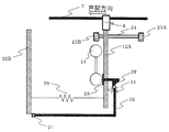
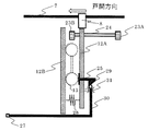
- FIG. 4 is a configuration diagram of the door device before the door opening start according to the first embodiment of the present invention.
- the door motor 9 In the fully closed state before the door opening starts after the car has landed, the door motor 9 generates a driving force in the door closing force direction in order to counter the door opening force caused by car opening of the passengers in the car and the car vibration at the time of raising and lowering. .
- the driving force is transmitted to the car engagement vane 12A through the belt grip 8.
- the car engaging vane 12A generates a driving force in the door closing direction on the car door panel 1 by contacting the car engaging vane stopper 23A installed on the car door panel 1A.
- the car engagement vane stopper 23A may be an elastic body such as rubber or a rigid body such as a bolt.
- the mechanical door closing force acts in the vicinity of the car door panel fully closed in accordance with the electric door closing force due to the driving force of the motor 9, so that the sum of the electric door closing force and the mechanical door closing force is obtained. This is a resistance against the door opening force described above.
- the door motor 9 When a door opening command is issued from the door control device 10, the door motor 9 generates a driving force in the door opening direction.
- the door motor 9 transmits the driving force in the door opening direction to the car engagement vane 12 ⁇ / b> A via the belt 7 and the belt grip 8.
- the car engagement vanes 12A operate along the slide guide 24 for smoothly operating in the door opening / closing direction, and the operation direction is restricted in the door opening direction or the door closing direction.
- driving force in the door opening direction is urged by the door motor 9
- only the car engaging vane 12A is driven until the contact detecting unit 25 attached to the car engaging vane 12A contacts the roller 13, and the car door panel. 1 does not work.
- a stopper portion 27 is provided at one end of the interlocking portion 26 that interlocks with the contact detection portion 25. Then, the car engaging vane 12B is fixed relative to the car engaging vane 12A by the stopper portion 27, and the distance between the car engaging vane 12A and the car engaging vane 12B does not change and is constant. Spacing is maintained.
- FIG. 5 is a configuration diagram of the door device immediately before the door opening engagement according to Embodiment 1 of the present invention.
- the contact detection unit 25 attached to the car engagement vane 12A detects the contact between the two.
- the contact detection unit 25 may be a mechanical or electrical switch or sensor, and may be detected from an electrical signal of the motor 9. 4 and 5 and FIG. 6 described later show examples of mechanical switches.
- the interlocking unit 26 rotates around the junction with the car engagement vane 12 ⁇ / b> A as a central axis according to the movement amount of the contact detection unit 25. And according to this rotation operation, the interlocking part 26 rotates, and the stopper part 27 provided at one end of the interlocking part 26 moves. And the stopper part 27 remove
- FIG. 6 is a configuration diagram of the door device at the time of door opening engagement according to Embodiment 1 of the present invention.
- the car engaging vane 12B from which the stopper portion 27 is removed and the other car engaging vane 12A receive a force in the direction of gripping the landing roller 13 by the gripping force spring 28. With this force, the car engagement vane 12B moves in the direction of the car engagement vane 12A, and the landing roller 13 can be sandwiched.
- the car door 1 and the car engagement vane 12A are fixed in accordance with the operation of the interlocking part 26 that is interlocked with the contact detection part 25, so that the car door 1 and the landing door 14 are connected and at the same time the car is engaged.
- the vane 12A and the car engaging vane 12B completely sandwich the landing roller 13.
- the operations of the car door 1 and the landing door 14 can be integrated. 4 to 6, the contact detection unit 25, the interlocking unit 26, the stopper unit 27, and the gripping force spring 28 are connected to maintain the connection state of the car door 1 and the landing door 14 during the opening / closing operation. It corresponds to a holding mechanism.
- the end portions of the slide guide 24 are provided with car engagement vane stoppers 23A and 23B, but they are not necessarily end portions, and may be installed on the car door panel 1A. Further, the car engagement vane stopper 23B is always installed on the door opening side with respect to the contact portion between the landing roller 13 and the car engagement vane 12A.
- the landing roller 13 When the car is not landing on the landing floor and the opening / closing command is transmitted to the door motor 9, the landing roller 13 does not exist at a position where it comes into contact with the contact detection unit 25. Accordingly, in this state, the car engaging vane 12A contacts the car engaging vane stopper 23A, whereby the car engaging vane 12A and the car door panel 1A are connected, and only the car door can be opened and closed.
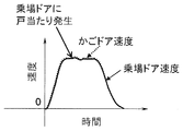
- FIG. 7 is a diagram for explaining the smoothness of the door opening operation of the car door 1 and the landing door 14 according to the first embodiment of the present invention.
- the landing door 14 is always connected to the car door 1.
- a smooth operation can be realized.
- the control device 10 generally performs speed control or position control of the elevator door so that the rotational speed of the motor 9 follows the target opening / closing speed command. For example, when the speed control is performed, the control device 10 corrects the current command value of the motor 9 based on the speed error between the actual speed of the motor 9 and the opening / closing speed command value.
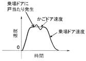
- FIG. 8 is a diagram for explaining the smoothness of the door opening operation of the car door 1 and the landing door 14 according to the conventional configuration.
- the conventional configuration for example, there is a gap between the car engagement vane 12B and the landing roller 13 when the door is opened.
- the contact between the car engagement vane 12A and the landing roller 13 is lost, and the landing door 14 can move by the gap.
- the landing door 14 loses connection with the car door 1 and the transmission force of the motor 9 is not transmitted to the landing door 14.
- the roller 13 of the landing door 14 repeatedly collides with the car engagement vane 12 and generates a flutter while generating noise, thereby increasing vibration and impairing comfort.
- the operation of the car door and the landing door is integrated in the door opening / closing after the landing of the car, and the connected state of the car door and the landing door is always maintained at all the door opening / closing positions. It is equipped with the structure. As a result, even when a disturbance such as a door stop of a passenger acts on the landing door, the operation of the car door and the landing door can always be matched, and the landing door can be operated smoothly.
- the car door and the landing door can be instantly and reliably connected when the contact is started. For this reason, the reliability of the connected state holding operation synchronized with the engaging operation can be improved.
- the engagement gap can be set large by adopting a configuration in which the contact between the car door engagement vane and the landing door roller is detected by the rotation operation of the contact detection unit. As a result, the maintenance load can be reduced.
- Embodiment 2 a configuration for maintaining the connected state of the car door 1 and the landing door 14 with a mechanism different from that of the first embodiment will be described.
- FIG. 9 is a configuration diagram of the door device before the opening of the door according to the second embodiment of the present invention.
- the door motor 9 When a door opening command is issued from the door control device 10, the door motor 9 generates a driving force in the door opening direction.
- the door motor 9 transmits the driving force in the door opening direction to the car engagement vane 12 ⁇ / b> A via the belt 7 and the belt grip 8.
- the car engagement vane 12A operates along a slide guide 24 for smoothly operating in the door opening / closing direction, and the operation direction is restricted in the door opening direction or door closing direction.
- the door motor 9 is energized in the door opening direction, only the car engagement vane 12A is driven until the contact detector 25 attached to the car engagement vane 12A contacts the roller 13, and the car door panel. 1 does not work.
- a cam portion 29 is attached to the contact detection portion 25.
- the cam portion 29 is fixed in contact with the interlocking portion 30 provided with the stopper portion 27 at one end. Therefore, in this state, the interval between the car engaging vane 12A and the car engaging vane 12B does not change, and a constant interval is maintained.
- FIG. 10 is a configuration diagram of the door device immediately before the door opening engagement according to the second embodiment of the present invention.
- the contact detection unit 25 attached to the car engagement vane 12A detects the contact between the two.
- the contact detection unit 25 may be a mechanical or electrical switch or sensor.
- FIG. 9 and FIG. 10 which are electrical signals of the motor 9, and FIG. Is shown.
- the contact detector 25 When the contact detector 25 comes into contact with the landing roller 13, the contact detector 25 slides in the horizontal direction. And according to the movement amount of the contact detection part 25, the cam part 29 attached to the contact detection part 25 slides similarly.
- the cam portion 29 is provided with an inclination, and the interlocking portion 30 moves in the vertical direction along the inclination.
- the moving direction of the interlocking portion 30 is regulated by the interlocking portion guide 31.
- the interlocking portion guide 31 is attached and fixed to the car engagement vane 12A.
- the stopper portion 27 provided at one end of the interlocking portion 30 moves in the vertical direction along with the movement of the interlocking portion 30, and the contact with the car engagement vane 12B is released.
- FIG. 11 is a configuration diagram of a door device at the time of door opening engagement according to Embodiment 2 of the present invention.
- the car engaging vane 12B from which the stopper portion 27 is removed and the other car engaging vane 12A receive a force in the direction of gripping the landing roller 13 by the gripping force spring 28. With this force, the car engagement vane 12B moves in the direction of the car engagement vane 12A, and the landing roller 13 can be sandwiched.
- the car door 1 and the car engagement vane 12A are fixed in accordance with the operation of the interlocking part 39 that is interlocked with the contact detection part 25, so that the car door 1 and the landing door 14 are connected and at the same time the car is engaged.
- the vane 12A and the car engaging vane 12B completely sandwich the landing roller 13.
- the operations of the car door 1 and the landing door 14 can be integrated.
- the contact detection unit 25, the stopper unit 27, the gripping force spring 28, the cam unit 29, the interlocking unit 30, and the interlocking unit guide 31 are connected to the car door 1 and the landing door 14 during the opening / closing operation. This corresponds to a connected state holding mechanism for maintaining the connected state.
- the landing door 14 is always connected to the car door 1.
- a smooth operation can be realized.
- a configuration capable of maintaining the connected state of the car door and the landing door is realized by a configuration different from that of the first embodiment. The same effect as in the first embodiment can be obtained.
- Embodiment 3 FIG. In the first and second embodiments, specific examples in which the contact detection unit 25 is configured by a mechanical switch have been described. On the other hand, in this Embodiment 3, the control method in case the contact detection part 25 is comprised with an electromechanical switch or a sensor is demonstrated to a specific example.
- the door control device 10 can know the start timing of door opening / closing by receiving a detection signal from the contact detection unit 25.
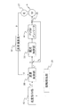
- FIG. 12 is a control block diagram of the door control device 10 according to the third embodiment of the present invention.
- the contact detection unit 25 detects the contact timing of the car engagement vane 12A and the landing roller 13 with an electrical switch or a sensor.
- the detection result is input to a speed command unit 32 that generates a door opening / closing speed command.
- the speed command unit 32 generates a door opening / closing speed command value (hereinafter simply referred to as a speed command value). Specifically, the speed command unit 32 is a speed command value based on a speed pattern set in advance based on a time from the start of opening / closing of the door panel or a motor rotation position, or a speed command value calculated sequentially. Is output.
- the speed command unit 32 generates the acceleration / deceleration speed command for opening / closing the door based on the contact timing detected by the contact detection unit 25, thereby reducing the door opening / closing distance by smooth acceleration and deceleration. It can be opened and closed in the time.
- the speed control unit 33 corrects the speed error between the actual motor speed V and the speed command value V *, and outputs a current command value Iq *. That is, the speed control unit 33 receives the difference between the speed command value V, which is the output of the speed command unit 32, and the actual speed V of the motor 9 obtained by the speed calculation unit 38 described later.
- the speed command unit 32 outputs a speed command value V * that is a target of the door opening / closing operation.
- a speed command value V * that is a target of the door opening / closing operation.
- disturbances such as running resistance such as clogging of dust, friction loss due to deformation of the door panel, and contact with an object being driven occur. For this reason, it is necessary to correct the speed error between the speed command value V * and the actual speed V by the speed control unit 33.
- the speed controller 33 receives the difference between the actual speed V and the speed command value V * as an input, and sets the current command value so that the actual speed V follows the target speed command value V * at regular time intervals. Control I *.
- K sp is a proportional gain
- K si is an integral gain
- s is a Laplace operator.
- the current control unit 34 controls the current value supplied to the motor 9 based on the current command value Iq * output from the speed control unit 33. At this time, the current control unit 34 feeds back a current value detected by the current detector 35 provided between the current control unit 34 and the motor 9 to control the current value supplied to the motor 9.
- the current command value output from the current control unit 34 is input to the motor 9 via the PWM inverter 36.
- the motor 9 generates a driving force for opening and closing the door panels 1A, 1B, 14A, and 14B according to the output of the PWM inverter 36.
- the sensor 37 is a rotation detection unit that is provided in the motor 9 and detects the rotation of the motor 9, and outputs the rotation position of the motor 9.
- FIG. 12 illustrates a case where the rotation position is detected using a sensor configured by an encoder or a resolver as the rotation detection unit.
- the motor rotational position or rotational speed may be estimated using the current value detected by the current detector 35.
- the speed calculation unit 38 calculates the rotational speed V of the motor 9 by sampling the rotational position input from the sensor 37 at regular intervals, and feeds it back to the speed control unit 33.
- the contact detection unit is configured by an electrical switch or a sensor instead of the mechanical switch, the same effect as in the first and second embodiments is achieved. Can be obtained.
- the operation of both can be integrated instantaneously when the connection between the car door and the landing door is started. As a result, an effect of shortening the door opening / closing time can be obtained.
- Embodiment 4 FIG. In the first to third embodiments, the case where the contact detection unit 25 is configured by a mechanical or electrical switch or sensor has been described. On the other hand, this Embodiment 4 demonstrates concretely the detection method comprised using the electrical signal of the motor 9 essential for door opening and closing, without using these additional apparatuses.
- the landing roller 13 includes the landing door 14, All the masses that affect the opening and closing of the landing door such as the landing door suspension 15 and the interlocking rope 21 are fixed.
- the mass affecting the opening / closing of the landing door is generally dominated by the mass of the landing door 14 depending on the width / height of the entrance / exit. Further, the landing door is required to have high rigidity so that the user does not come into contact with the closed landing door and fall into the hoistway when the elevator car has not arrived. For this reason, the mass affecting the opening and closing of the landing door is several tens of kg or more.
- the mass driven by the motor 9 before the car-engaging vane 12 and the landing roller 13 come into contact is mainly dominated by the car-engaging vane 12. It becomes. That is, before and after the car-engaging vane 12 and the landing roller 13 come into contact with each other, a large fluctuation occurs in the motor shaft equivalent inertia value of the motor 9, that is, the mass corresponding to the driving load.
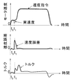
- FIG. 13 is a diagram for explaining a contact detection method based on the electric signal waveform of the motor 9 when the door is opened according to the fourth embodiment of the present invention. Specifically, the upper part shows the time change of the motor speed with respect to the speed command and the actual speed, the middle part shows the time change of the speed error between the speed command and the actual speed, and the lower part shows the torque of the motor 9. The time change of is shown.
- the door motor 9 When a door opening command is issued from the door control device 10, the door motor 9 generates a driving force in the door opening direction at time t0. Then, after driving the belt 7, the belt grip 8, and the car engaging vane 12, the car engaging vane 12 and the landing roller 13 come into contact at time t1.
- time t1 After time t1, it is connected to the mass that affects the opening and closing of the landing door via the landing roller 13, and the door is opened.
- the landing roller 13 comes into contact with the mass that affects the opening and closing of the car door, the door is opened with the total mass of the car door and the landing door.
- the mass affecting the opening and closing of the car door is the same as that of the landing door, and the door panel material may be different between the car door and the landing door, or the entrance width and height may be different. In any case, however, the mass corresponding to the driving load of the motor 9 greatly fluctuates before and after the car engagement vanes 12 and the landing rollers 13 come into contact with each other.
- the actual speed V of the motor 9 is monitored, or the torque calculated from the current command value Iq * of the motor 9 is monitored. There is a technique to do.
- the method of monitoring the actual speed V of the motor 9 can be easily realized by monitoring the speed error between the actual speed V and the speed command value V * as shown in the middle diagram of FIG.
- the proportional gain Ksp and integral gain Ksi of the speed control unit 33 are designed based on the inertia value mainly assuming the load mass of the car engagement vane 12 at the time t0, the speed command value V at the time t1.
- the speed error which is the difference between the actual speed V and *, increases.
- the timing at which the speed error exceeds a certain threshold or a variable threshold based on the door mass is the time when the car engagement vane 12 and the landing roller 13 are in contact, and the contact can be detected from this timing.
- the method of monitoring the torque calculated from the current command value Iq * of the motor 9 is such that, as shown in the lower diagram of FIG. 13, the torque value after time t0 is small, and the landing roller 13 is contacted at time t1. Thereafter, in order to drive the door, it is only necessary to capture the characteristic that the torque value increases. Therefore, the contact can be detected by assuming that the case where the torque value exceeds a certain threshold value or a variable threshold value based on the door mass is the time when the engagement vane 12 and the landing roller 13 contact each other.
- the current command value Iq * that is, the torque increases sharply. From this, the contact may be detected when the time differential value of the torque exceeds a certain threshold value.
- the use of the electrical signal of the motor 9 means that the control device 10 that controls the motor 9 using the electrical signal determines contact detection. Therefore, if the interlocking unit 26 is a rotary motor, the rotary motor may be driven in response to a contact detection signal from the control device 10 by wire or wirelessly.
- the cam unit 29 is a motor that slides in the horizontal direction, this motor may be driven in accordance with a contact detection signal from the control device 10 by wire or wirelessly.
- the contact detection unit 25 may be configured by a mechanical or electrical switch or sensor, and an electrical signal from the motor 9 may also be used to detect contact.
- the torque is calculated from the current command value Iq *. However, it is assumed that the current value detected by the current detector 35 follows the current command value Iq *. For this reason, the torque may be calculated from the current value detected by the current detector 35.
- the fourth embodiment even when contact detection is performed based on the electric signal of the motor, the same effect as in the third embodiment can be obtained.
- the configuration of the device can be minimized. As a result, the space limited to the elevator car and the landing can be used effectively.
Landscapes
- Engineering & Computer Science (AREA)
- Automation & Control Theory (AREA)
- Elevator Door Apparatuses (AREA)
Abstract
La présente invention est pourvue de : des panneaux de porte qui comprennent un panneau de porte de cabine et un panneau de porte de palier d'accès pour ouvrir/fermer l'entrée; un moteur qui délivre une force d'entraînement; et une partie mécanisme de mise en prise qui amène le panneau de porte de cabine et le panneau de porte de palier d'accès à être en prise l'un avec l'autre lorsqu'une opération d'ouverture/fermeture des deux panneaux de porte de manière imbriquée doit être effectuée au moment de l'arrivée sur le palier, la partie mécanisme de mise en prise amenant, au moment d'une opération d'ouverture/fermeture des panneaux de porte au moment de l'arrivée sur le palier, le panneau de porte de cabine et le panneau de porte de palier d'accès dans un état lié en synchronisation avec un moment où le panneau de porte de cabine et le panneau de porte de palier d'accès sont en prise et viennent en contact l'un avec l'autre, puis conserve l'état lié à toutes les positions d'ouverture/fermeture.
Priority Applications (2)
| Application Number | Priority Date | Filing Date | Title |
|---|---|---|---|
| JP2017539464A JP6373507B2 (ja) | 2016-02-26 | 2016-12-15 | エレベータのドア装置 |
| CN201680031001.XA CN107614412B (zh) | 2016-02-26 | 2016-12-15 | 电梯的门装置 |
Applications Claiming Priority (2)
| Application Number | Priority Date | Filing Date | Title |
|---|---|---|---|
| JP2016-035346 | 2016-02-26 | ||
| JP2016035346 | 2016-02-26 |
Publications (1)
| Publication Number | Publication Date |
|---|---|
| WO2017145501A1 true WO2017145501A1 (fr) | 2017-08-31 |
Family
ID=59686098
Family Applications (1)
| Application Number | Title | Priority Date | Filing Date |
|---|---|---|---|
| PCT/JP2016/087442 Ceased WO2017145501A1 (fr) | 2016-02-26 | 2016-12-15 | Dispositif de porte pour ascenseur |
Country Status (3)
| Country | Link |
|---|---|
| JP (1) | JP6373507B2 (fr) |
| CN (1) | CN107614412B (fr) |
| WO (1) | WO2017145501A1 (fr) |
Cited By (3)
| Publication number | Priority date | Publication date | Assignee | Title |
|---|---|---|---|---|
| CN111320063A (zh) * | 2020-03-19 | 2020-06-23 | 嘉世达电梯有限公司 | 一种高速电梯的新型厅门结构及其维护方法 |
| CN112299212A (zh) * | 2020-05-07 | 2021-02-02 | 苏州启元电梯系统有限公司 | 一种可调节斜行角度的电梯层门锁 |
| CN116081437A (zh) * | 2021-11-05 | 2023-05-09 | 菱王电梯有限公司 | 电梯及其门刀装置 |
Families Citing this family (8)
| Publication number | Priority date | Publication date | Assignee | Title |
|---|---|---|---|---|
| US11040858B2 (en) | 2018-05-01 | 2021-06-22 | Otis Elevator Company | Elevator door interlock assembly |
| US11034548B2 (en) | 2018-05-01 | 2021-06-15 | Otis Elevator Company | Elevator door interlock assembly |
| US11040852B2 (en) | 2018-05-01 | 2021-06-22 | Otis Elevator Company | Elevator car control to address abnormal passenger behavior |
| US11155444B2 (en) | 2018-05-01 | 2021-10-26 | Otis Elevator Company | Elevator door interlock assembly |
| US11046557B2 (en) | 2018-05-01 | 2021-06-29 | Otis Elevator Company | Elevator door interlock assembly |
| CN110921468B (zh) * | 2019-12-30 | 2022-08-09 | 苏州和阳电气有限公司 | 一种门刀距离获取方法和装置 |
| CN114787069B (zh) * | 2020-01-07 | 2024-06-18 | 株式会社日立制作所 | 电梯以及电梯的控制方法 |
| US11760604B1 (en) | 2022-05-27 | 2023-09-19 | Otis Elevator Company | Versatile elevator door interlock assembly |
Citations (2)
| Publication number | Priority date | Publication date | Assignee | Title |
|---|---|---|---|---|
| WO2012127607A1 (fr) * | 2011-03-22 | 2012-09-27 | 三菱電機株式会社 | Dispositif de commande de porte d'ascenseur |
| JP2013163555A (ja) * | 2012-02-09 | 2013-08-22 | Toshiba Elevator Co Ltd | エレベータのドア装置 |
Family Cites Families (2)
| Publication number | Priority date | Publication date | Assignee | Title |
|---|---|---|---|---|
| WO2009011044A1 (fr) * | 2007-07-18 | 2009-01-22 | Mitsubishi Electric Corporation | Dispositif d'engagement de porte pour ascenseur |
| JP2012001288A (ja) * | 2010-06-14 | 2012-01-05 | Hitachi Ltd | エレベーターのドア開閉装置及びエレベーターのドア開閉方法 |
-
2016
- 2016-12-15 WO PCT/JP2016/087442 patent/WO2017145501A1/fr not_active Ceased
- 2016-12-15 CN CN201680031001.XA patent/CN107614412B/zh active Active
- 2016-12-15 JP JP2017539464A patent/JP6373507B2/ja active Active
Patent Citations (2)
| Publication number | Priority date | Publication date | Assignee | Title |
|---|---|---|---|---|
| WO2012127607A1 (fr) * | 2011-03-22 | 2012-09-27 | 三菱電機株式会社 | Dispositif de commande de porte d'ascenseur |
| JP2013163555A (ja) * | 2012-02-09 | 2013-08-22 | Toshiba Elevator Co Ltd | エレベータのドア装置 |
Cited By (3)
| Publication number | Priority date | Publication date | Assignee | Title |
|---|---|---|---|---|
| CN111320063A (zh) * | 2020-03-19 | 2020-06-23 | 嘉世达电梯有限公司 | 一种高速电梯的新型厅门结构及其维护方法 |
| CN112299212A (zh) * | 2020-05-07 | 2021-02-02 | 苏州启元电梯系统有限公司 | 一种可调节斜行角度的电梯层门锁 |
| CN116081437A (zh) * | 2021-11-05 | 2023-05-09 | 菱王电梯有限公司 | 电梯及其门刀装置 |
Also Published As
| Publication number | Publication date |
|---|---|
| CN107614412A (zh) | 2018-01-19 |
| CN107614412B (zh) | 2019-05-31 |
| JP6373507B2 (ja) | 2018-08-15 |
| JPWO2017145501A1 (ja) | 2018-03-08 |
Similar Documents
| Publication | Publication Date | Title |
|---|---|---|
| JP6373507B2 (ja) | エレベータのドア装置 | |
| CN105283402B (zh) | 门装置和门的控制方法 | |
| JP6095011B2 (ja) | エレベーターのドア制御装置およびその方法 | |
| JP6279072B2 (ja) | エレベータのドア制御装置、及びドア制御方法 | |
| CN102482057A (zh) | 电梯门装置 | |
| JP2009214952A (ja) | エレベーターのドア装置 | |
| WO2014141384A1 (fr) | Dispositif de commande de porte d'ascenseur | |
| KR101862970B1 (ko) | 엘리베이터 장치 | |
| JP5585218B2 (ja) | エレベータのドア制御装置 | |
| JP6556028B2 (ja) | エレベータのドア装置 | |
| JPH0684233B2 (ja) | エレベーター装置及びその運転制御方法 | |
| CN103459295B (zh) | 电梯的门控制装置 | |
| US20200039794A1 (en) | Lost motion assembly | |
| JP6862605B2 (ja) | エレベータードアの係合装置およびエレベータードア装置 | |
| JPH1067480A (ja) | エレベータのかごドア装置 | |
| CN105800433B (zh) | 电梯的门装置 | |
| JP2009166933A (ja) | エレベータの安全装置 | |
| KR102695350B1 (ko) | 멀티 카 엘리베이터 제어 장치 | |
| JP2013107733A (ja) | エレベータの給電制御システム | |
| JP4245372B2 (ja) | エレベータのドア制御装置 | |
| JP2005082272A (ja) | 乗り場扉とエレベータ装置 | |
| HK40008590A (en) | Elevator malfunction remote recovery system and elevator malfunction recovery system | |
| HK40008590B (en) | Elevator malfunction remote recovery system and elevator malfunction recovery system |
Legal Events
| Date | Code | Title | Description |
|---|---|---|---|
| ENP | Entry into the national phase |
Ref document number: 2017539464 Country of ref document: JP Kind code of ref document: A |
|
| NENP | Non-entry into the national phase |
Ref country code: DE |
|
| 121 | Ep: the epo has been informed by wipo that ep was designated in this application |
Ref document number: 16891657 Country of ref document: EP Kind code of ref document: A1 |
|
| 122 | Ep: pct application non-entry in european phase |
Ref document number: 16891657 Country of ref document: EP Kind code of ref document: A1 |