WO2017145554A1 - 内燃機関制御装置 - Google Patents
内燃機関制御装置 Download PDFInfo
- Publication number
- WO2017145554A1 WO2017145554A1 PCT/JP2017/000914 JP2017000914W WO2017145554A1 WO 2017145554 A1 WO2017145554 A1 WO 2017145554A1 JP 2017000914 W JP2017000914 W JP 2017000914W WO 2017145554 A1 WO2017145554 A1 WO 2017145554A1
- Authority
- WO
- WIPO (PCT)
- Prior art keywords
- ignition timing
- cylinder
- internal combustion
- combustion engine
- temperature
- Prior art date
- Legal status (The legal status is an assumption and is not a legal conclusion. Google has not performed a legal analysis and makes no representation as to the accuracy of the status listed.)
- Ceased
Links
Images





Classifications
-
- F—MECHANICAL ENGINEERING; LIGHTING; HEATING; WEAPONS; BLASTING
- F02—COMBUSTION ENGINES; HOT-GAS OR COMBUSTION-PRODUCT ENGINE PLANTS
- F02D—CONTROLLING COMBUSTION ENGINES
- F02D13/00—Controlling the engine output power by varying inlet or exhaust valve operating characteristics, e.g. timing
- F02D13/02—Controlling the engine output power by varying inlet or exhaust valve operating characteristics, e.g. timing during engine operation
- F02D13/0261—Controlling the valve overlap
-
- F—MECHANICAL ENGINEERING; LIGHTING; HEATING; WEAPONS; BLASTING
- F02—COMBUSTION ENGINES; HOT-GAS OR COMBUSTION-PRODUCT ENGINE PLANTS
- F02D—CONTROLLING COMBUSTION ENGINES
- F02D13/00—Controlling the engine output power by varying inlet or exhaust valve operating characteristics, e.g. timing
- F02D13/02—Controlling the engine output power by varying inlet or exhaust valve operating characteristics, e.g. timing during engine operation
- F02D13/0203—Variable control of intake and exhaust valves
- F02D13/0215—Variable control of intake and exhaust valves changing the valve timing only
-
- F—MECHANICAL ENGINEERING; LIGHTING; HEATING; WEAPONS; BLASTING
- F02—COMBUSTION ENGINES; HOT-GAS OR COMBUSTION-PRODUCT ENGINE PLANTS
- F02D—CONTROLLING COMBUSTION ENGINES
- F02D15/00—Varying compression ratio
- F02D15/02—Varying compression ratio by alteration or displacement of piston stroke
-
- F—MECHANICAL ENGINEERING; LIGHTING; HEATING; WEAPONS; BLASTING
- F02—COMBUSTION ENGINES; HOT-GAS OR COMBUSTION-PRODUCT ENGINE PLANTS
- F02D—CONTROLLING COMBUSTION ENGINES
- F02D37/00—Non-electrical conjoint control of two or more functions of engines, not otherwise provided for
- F02D37/02—Non-electrical conjoint control of two or more functions of engines, not otherwise provided for one of the functions being ignition
-
- F—MECHANICAL ENGINEERING; LIGHTING; HEATING; WEAPONS; BLASTING
- F02—COMBUSTION ENGINES; HOT-GAS OR COMBUSTION-PRODUCT ENGINE PLANTS
- F02D—CONTROLLING COMBUSTION ENGINES
- F02D41/00—Electrical control of supply of combustible mixture or its constituents
- F02D41/0002—Controlling intake air
-
- F—MECHANICAL ENGINEERING; LIGHTING; HEATING; WEAPONS; BLASTING
- F02—COMBUSTION ENGINES; HOT-GAS OR COMBUSTION-PRODUCT ENGINE PLANTS
- F02D—CONTROLLING COMBUSTION ENGINES
- F02D41/00—Electrical control of supply of combustible mixture or its constituents
- F02D41/02—Circuit arrangements for generating control signals
- F02D41/021—Introducing corrections for particular conditions exterior to the engine
- F02D41/0235—Introducing corrections for particular conditions exterior to the engine in relation with the state of the exhaust gas treating apparatus
- F02D41/024—Introducing corrections for particular conditions exterior to the engine in relation with the state of the exhaust gas treating apparatus to increase temperature of the exhaust gas treating apparatus
- F02D41/0255—Introducing corrections for particular conditions exterior to the engine in relation with the state of the exhaust gas treating apparatus to increase temperature of the exhaust gas treating apparatus to accelerate the warming-up of the exhaust gas treating apparatus at engine start
-
- F—MECHANICAL ENGINEERING; LIGHTING; HEATING; WEAPONS; BLASTING
- F02—COMBUSTION ENGINES; HOT-GAS OR COMBUSTION-PRODUCT ENGINE PLANTS
- F02D—CONTROLLING COMBUSTION ENGINES
- F02D41/00—Electrical control of supply of combustible mixture or its constituents
- F02D41/02—Circuit arrangements for generating control signals
- F02D41/04—Introducing corrections for particular operating conditions
- F02D41/06—Introducing corrections for particular operating conditions for engine starting or warming up
- F02D41/062—Introducing corrections for particular operating conditions for engine starting or warming up for starting
- F02D41/064—Introducing corrections for particular operating conditions for engine starting or warming up for starting at cold start
-
- F—MECHANICAL ENGINEERING; LIGHTING; HEATING; WEAPONS; BLASTING
- F02—COMBUSTION ENGINES; HOT-GAS OR COMBUSTION-PRODUCT ENGINE PLANTS
- F02D—CONTROLLING COMBUSTION ENGINES
- F02D41/00—Electrical control of supply of combustible mixture or its constituents
- F02D41/02—Circuit arrangements for generating control signals
- F02D41/04—Introducing corrections for particular operating conditions
- F02D41/06—Introducing corrections for particular operating conditions for engine starting or warming up
- F02D41/068—Introducing corrections for particular operating conditions for engine starting or warming up for warming-up
-
- F—MECHANICAL ENGINEERING; LIGHTING; HEATING; WEAPONS; BLASTING
- F02—COMBUSTION ENGINES; HOT-GAS OR COMBUSTION-PRODUCT ENGINE PLANTS
- F02D—CONTROLLING COMBUSTION ENGINES
- F02D43/00—Conjoint electrical control of two or more functions, e.g. ignition, fuel-air mixture, recirculation, supercharging or exhaust-gas treatment
-
- F—MECHANICAL ENGINEERING; LIGHTING; HEATING; WEAPONS; BLASTING
- F02—COMBUSTION ENGINES; HOT-GAS OR COMBUSTION-PRODUCT ENGINE PLANTS
- F02P—IGNITION, OTHER THAN COMPRESSION IGNITION, FOR INTERNAL-COMBUSTION ENGINES; TESTING OF IGNITION TIMING IN COMPRESSION-IGNITION ENGINES
- F02P5/00—Advancing or retarding ignition; Control therefor
- F02P5/04—Advancing or retarding ignition; Control therefor automatically, as a function of the working conditions of the engine or vehicle or of the atmospheric conditions
- F02P5/145—Advancing or retarding ignition; Control therefor automatically, as a function of the working conditions of the engine or vehicle or of the atmospheric conditions using electrical means
- F02P5/15—Digital data processing
- F02P5/1502—Digital data processing using one central computing unit
- F02P5/1504—Digital data processing using one central computing unit with particular means during a transient phase, e.g. acceleration, deceleration, gear change
-
- F—MECHANICAL ENGINEERING; LIGHTING; HEATING; WEAPONS; BLASTING
- F02—COMBUSTION ENGINES; HOT-GAS OR COMBUSTION-PRODUCT ENGINE PLANTS
- F02P—IGNITION, OTHER THAN COMPRESSION IGNITION, FOR INTERNAL-COMBUSTION ENGINES; TESTING OF IGNITION TIMING IN COMPRESSION-IGNITION ENGINES
- F02P5/00—Advancing or retarding ignition; Control therefor
- F02P5/04—Advancing or retarding ignition; Control therefor automatically, as a function of the working conditions of the engine or vehicle or of the atmospheric conditions
- F02P5/145—Advancing or retarding ignition; Control therefor automatically, as a function of the working conditions of the engine or vehicle or of the atmospheric conditions using electrical means
- F02P5/15—Digital data processing
- F02P5/1502—Digital data processing using one central computing unit
- F02P5/1506—Digital data processing using one central computing unit with particular means during starting
-
- F—MECHANICAL ENGINEERING; LIGHTING; HEATING; WEAPONS; BLASTING
- F02—COMBUSTION ENGINES; HOT-GAS OR COMBUSTION-PRODUCT ENGINE PLANTS
- F02B—INTERNAL-COMBUSTION PISTON ENGINES; COMBUSTION ENGINES IN GENERAL
- F02B75/00—Other engines
- F02B75/12—Other methods of operation
- F02B2075/125—Direct injection in the combustion chamber for spark ignition engines, i.e. not in pre-combustion chamber
-
- F—MECHANICAL ENGINEERING; LIGHTING; HEATING; WEAPONS; BLASTING
- F02—COMBUSTION ENGINES; HOT-GAS OR COMBUSTION-PRODUCT ENGINE PLANTS
- F02D—CONTROLLING COMBUSTION ENGINES
- F02D13/00—Controlling the engine output power by varying inlet or exhaust valve operating characteristics, e.g. timing
- F02D13/02—Controlling the engine output power by varying inlet or exhaust valve operating characteristics, e.g. timing during engine operation
- F02D13/0223—Variable control of the intake valves only
- F02D13/0234—Variable control of the intake valves only changing the valve timing only
-
- F—MECHANICAL ENGINEERING; LIGHTING; HEATING; WEAPONS; BLASTING
- F02—COMBUSTION ENGINES; HOT-GAS OR COMBUSTION-PRODUCT ENGINE PLANTS
- F02D—CONTROLLING COMBUSTION ENGINES
- F02D13/00—Controlling the engine output power by varying inlet or exhaust valve operating characteristics, e.g. timing
- F02D13/02—Controlling the engine output power by varying inlet or exhaust valve operating characteristics, e.g. timing during engine operation
- F02D13/0261—Controlling the valve overlap
- F02D13/0265—Negative valve overlap for temporarily storing residual gas in the cylinder
-
- F—MECHANICAL ENGINEERING; LIGHTING; HEATING; WEAPONS; BLASTING
- F02—COMBUSTION ENGINES; HOT-GAS OR COMBUSTION-PRODUCT ENGINE PLANTS
- F02D—CONTROLLING COMBUSTION ENGINES
- F02D41/00—Electrical control of supply of combustible mixture or its constituents
- F02D41/0002—Controlling intake air
- F02D2041/001—Controlling intake air for engines with variable valve actuation
-
- F—MECHANICAL ENGINEERING; LIGHTING; HEATING; WEAPONS; BLASTING
- F02—COMBUSTION ENGINES; HOT-GAS OR COMBUSTION-PRODUCT ENGINE PLANTS
- F02D—CONTROLLING COMBUSTION ENGINES
- F02D21/00—Controlling engines characterised by their being supplied with non-airborne oxygen or other non-fuel gas
- F02D21/06—Controlling engines characterised by their being supplied with non-airborne oxygen or other non-fuel gas peculiar to engines having other non-fuel gas added to combustion air
- F02D21/10—Controlling engines characterised by their being supplied with non-airborne oxygen or other non-fuel gas peculiar to engines having other non-fuel gas added to combustion air having secondary air added to the fuel-air mixture
-
- F—MECHANICAL ENGINEERING; LIGHTING; HEATING; WEAPONS; BLASTING
- F02—COMBUSTION ENGINES; HOT-GAS OR COMBUSTION-PRODUCT ENGINE PLANTS
- F02D—CONTROLLING COMBUSTION ENGINES
- F02D41/00—Electrical control of supply of combustible mixture or its constituents
- F02D41/02—Circuit arrangements for generating control signals
- F02D41/14—Introducing closed-loop corrections
- F02D41/1497—With detection of the mechanical response of the engine
-
- F—MECHANICAL ENGINEERING; LIGHTING; HEATING; WEAPONS; BLASTING
- F02—COMBUSTION ENGINES; HOT-GAS OR COMBUSTION-PRODUCT ENGINE PLANTS
- F02D—CONTROLLING COMBUSTION ENGINES
- F02D41/00—Electrical control of supply of combustible mixture or its constituents
- F02D41/30—Controlling fuel injection
- F02D41/3011—Controlling fuel injection according to or using specific or several modes of combustion
- F02D41/3017—Controlling fuel injection according to or using specific or several modes of combustion characterised by the mode(s) being used
- F02D41/3035—Controlling fuel injection according to or using specific or several modes of combustion characterised by the mode(s) being used a mode being the premixed charge compression-ignition mode
-
- F—MECHANICAL ENGINEERING; LIGHTING; HEATING; WEAPONS; BLASTING
- F02—COMBUSTION ENGINES; HOT-GAS OR COMBUSTION-PRODUCT ENGINE PLANTS
- F02M—SUPPLYING COMBUSTION ENGINES IN GENERAL WITH COMBUSTIBLE MIXTURES OR CONSTITUENTS THEREOF
- F02M23/00—Apparatus for adding secondary air to fuel-air mixture
- F02M2023/008—Apparatus for adding secondary air to fuel-air mixture by injecting compressed air directly into the combustion chamber
-
- Y—GENERAL TAGGING OF NEW TECHNOLOGICAL DEVELOPMENTS; GENERAL TAGGING OF CROSS-SECTIONAL TECHNOLOGIES SPANNING OVER SEVERAL SECTIONS OF THE IPC; TECHNICAL SUBJECTS COVERED BY FORMER USPC CROSS-REFERENCE ART COLLECTIONS [XRACs] AND DIGESTS
- Y02—TECHNOLOGIES OR APPLICATIONS FOR MITIGATION OR ADAPTATION AGAINST CLIMATE CHANGE
- Y02T—CLIMATE CHANGE MITIGATION TECHNOLOGIES RELATED TO TRANSPORTATION
- Y02T10/00—Road transport of goods or passengers
- Y02T10/10—Internal combustion engine [ICE] based vehicles
- Y02T10/12—Improving ICE efficiencies
-
- Y—GENERAL TAGGING OF NEW TECHNOLOGICAL DEVELOPMENTS; GENERAL TAGGING OF CROSS-SECTIONAL TECHNOLOGIES SPANNING OVER SEVERAL SECTIONS OF THE IPC; TECHNICAL SUBJECTS COVERED BY FORMER USPC CROSS-REFERENCE ART COLLECTIONS [XRACs] AND DIGESTS
- Y02—TECHNOLOGIES OR APPLICATIONS FOR MITIGATION OR ADAPTATION AGAINST CLIMATE CHANGE
- Y02T—CLIMATE CHANGE MITIGATION TECHNOLOGIES RELATED TO TRANSPORTATION
- Y02T10/00—Road transport of goods or passengers
- Y02T10/10—Internal combustion engine [ICE] based vehicles
- Y02T10/40—Engine management systems
Definitions
- the present invention relates to an internal combustion engine in which fuel is directly injected into a cylinder and burned mainly by ignition.
- a spark ignition gasoline engine that directly injects fuel into a cylinder is known.
- it is effective by injecting fuel during the compression stroke at the start, making the air-fuel mixture be biased near the spark plug, and at the same time retarding the ignition timing (retard)
- a method for increasing the exhaust temperature by increasing the proportion of so-called after-burning that does not result in excessive torque, increasing the exhaust temperature, and reducing unburned hydrocarbons (hereinafter referred to as HC) in the exhaust is widely known.
- JP-A-8-291729 Patent Document 1
- the retard amount of the ignition timing increases, the exhaust temperature can be raised, which is advantageous for early activation of the catalyst, but the combustion stability tends to deteriorate with the retard.
- the retard amount is determined by referring to a control computer map for a predetermined value according to the oil temperature or the like. Immediately after the start of cold engine, the temperature in the cylinder is low, so that it is not possible to take a large ignition timing retard to avoid combustion instability, and it takes time to activate the catalyst downstream of the internal combustion engine was there.
- An object of the present invention is to quickly raise the temperature in the cylinder immediately after starting to increase the ignition timing retard amount and to reduce the HC emission amount by early activation of the catalyst.
- the present invention provides an internal combustion engine control device including an ignition timing control unit that controls the ignition timing of an ignition device attached to the internal combustion engine, and includes an in-cylinder temperature raising unit that raises the temperature in the cylinder.
- the in-cylinder temperature raising unit raises the in-cylinder temperature, and the ignition timing control unit increases the retard amount of the ignition timing of the ignition device.
- the control is performed with priority given to the temperature rise in the cylinder, whereby the combustion stability can be ensured and the retard amount of the ignition timing can be increased accordingly.
- the retard amount at the ignition timing By increasing the retard amount at the ignition timing, the amount of heat flowing to the exhaust pipe is increased, the catalyst warm-up time is shortened, and the exhaust at the time of starting is reduced.
- FIG. 1 is a system configuration diagram in which an engine control apparatus according to a first embodiment of the present invention is applied to an in-cylinder gasoline engine for automobiles.
- the system block diagram which shows an example of control from the start of a general engine control apparatus to the end of catalyst warm-up.
- the system block diagram which shows an example of the control from the start of the engine control apparatus by 1st Example of this invention to the completion
- the cam profile figure which shows operation
- the time chart which shows the valve timing in the control apparatus of the engine by the 1st Example of this invention.
- FIG. 1 is a system configuration diagram in which the engine control device according to this embodiment is applied to an in-cylinder gasoline injection engine for automobiles.
- Engine 100 is a four-cylinder gasoline engine for automobiles that performs spark ignition combustion.
- An air flow sensor 1 for measuring the intake air amount
- a supercharger compressor 4a for supercharging intake air
- an intercooler 7 for cooling intake air
- an electronic control throttle 2 for adjusting intake pipe pressure
- An intake pressure sensor 14 for measuring the pressure in the manifold 6 is provided at an appropriate position of each intake pipe.
- the engine 100 also includes a fuel injection device (hereinafter referred to as an injector) 13 for injecting fuel into the cylinder 15 of each cylinder, a piston 18 for compressing a mixture of injected fuel and air, and ignition energy.
- a spark plug 17 is provided for each cylinder.
- the intake valve 5c that opens when the gas flows into the cylinder, the exhaust valve 5d that opens when the gas exhausts, and the opening and closing timing of the intake and exhaust valves are adjusted to adjust the gas flowing into or out of the cylinder.
- the variable valve timing mechanism 5a (intake side) and 5b (exhaust side) are provided in the cylinder head.
- the intake air amount and the internal EGR amount are adjusted by adjusting the valve opening and closing timings of the intake and exhaust valves of all the cylinders from No. 1 to No. 4 by the variable valve timings 5a and 5b.
- a high pressure fuel pump for supplying high pressure fuel to the injector 13 is connected to the injector 13 by a fuel pipe, and a fuel pressure sensor for measuring the fuel injection pressure is provided in the fuel pipe. Is provided.
- a turbine 4b for applying a rotational force to the compressor 4a of the supercharger by exhaust energy
- an electronically controlled waste gate valve 11 for adjusting an exhaust flow rate flowing through the turbine
- a three-way catalyst 10 for purifying the exhaust
- An air-fuel ratio sensor 9 which is an aspect of the air-fuel ratio detector and detects the air-fuel ratio of exhaust on the upstream side of the three-way catalyst 10, is provided at each appropriate position of the exhaust pipe 16.
- the crankshaft is provided with a crank angle sensor for calculating a rotation angle.
- an EGR pipe 40 for recirculating exhaust gas from the downstream side of the exhaust pipe catalyst 10 to the upstream side of the intake pipe compressor 4a is provided.
- the EGR cooler 42 for cooling the EGR, the EGR valve 41 for controlling the EGR flow rate, the differential pressure sensor 43 for detecting the differential pressure before and after the EGR valve, and the EGR temperature sensor 44 for detecting the EGR temperature include an EGR pipe.
- Each of 40 is attached at an appropriate position.
- Signals obtained from the airflow sensor 1, air-fuel ratio sensor 9, intake pressure sensor 14, differential pressure sensor 43, and EGR temperature sensor 44 are sent to an engine control unit (ECU) 20.
- a signal obtained from the accelerator opening sensor 12 is sent to the ECU 20.
- the accelerator opening sensor 12 detects the depression amount of the accelerator pedal, that is, the accelerator opening.
- the ECU 20 calculates the required torque based on the output signal of the accelerator opening sensor 12. That is, the accelerator opening sensor 12 is used as a required torque detection sensor that detects a required torque for the engine.
- ECU20 calculates the rotational speed of an engine based on the output signal of a crank angle sensor.
- the ECU 20 optimally calculates main operating amounts of the engine such as the air flow rate, the fuel injection amount, the ignition timing, and the fuel pressure based on the operating state of the engine obtained from the outputs of the various sensors.
- the fuel injection amount calculated by the ECU 20 is converted into a valve opening pulse signal and sent to the injector 13. Further, an ignition signal is sent to the spark plug 17 so as to be ignited at the ignition timing calculated by the ECU 20.
- the throttle opening calculated by the ECU 20 is sent to the electronic control throttle 2 as a throttle drive signal.
- the variable valve timing operation amount calculated by the ECU 20 is sent to the variable valve timing 5 as a variable valve timing drive signal.
- the waste gate valve 11 is a device that regulates the amount of inflow into the compressor by fractionating a part of the exhaust gas.
- the waste gate valve opening calculated by the ECU 20 is sent to the waste gate valve 11 as a waste gate valve drive signal.
- the EGR valve opening calculated by the ECU 20 is sent to the EGR valve 41 as an EGR valve opening driving signal.
- the fuel is injected into the air flowing into the cylinder 15 from the intake pipe through the intake valve to form an air-fuel mixture.
- the air-fuel mixture explodes due to sparks generated from the spark plug 17 at a predetermined ignition timing, and the piston is pushed down by the combustion pressure to become engine driving force. Further, the exhaust gas after the explosion is sent to the three-way catalyst 10 through the exhaust pipe 16, and the exhaust components are purified in the three-way catalyst 10 and discharged to the outside.
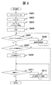
- FIG. 2 is a system block diagram showing an example of a control flow from engine start of the engine control device to completion of catalyst warm-up.
- the ignition key is turned on in step S601
- the process proceeds to S602, and energization to the ECU 20 is turned on.
- the starter motor is driven to start rotation of the crankshaft.
- the engine is started by fuel injection and ignition.
- the engine speed is temporarily set to a higher speed than the idle state in order to keep the engine rotating and warm up the engine. This is called a fast idle state. If it is determined in S605 that the engine is in the fast idle state after the engine is started, it is determined in S607 whether the engine is in a cold state.
- the ECU 21 determines whether or not the engine 100 is in a cold state based on the oil temperature and water temperature in the engine.
- the oil temperature is the temperature of the engine oil that circulates inside the engine in order to increase the lubricity of the sliding parts in the engine such as the variable valve timings 5a and 5b and the piston 18.
- the water temperature is the temperature of cooling water that flows outside the wall surface of the cylinder 15 and protects the engine from the heat generated by combustion. Both the oil temperature and the water temperature are detected by a temperature sensor embedded in the engine. For example, the ECU 21 determines that the engine is cold when both the oil temperature and the water temperature are 80 ° C. or less.
- warm-up by the ignition timing retard is started in S608 to retard the ignition timing after the top dead center.
- the ignition timing is retarded, the period during which the combustion gas pushes down the piston and works is decreased, and the ratio of exhaust loss in the total energy generated by combustion is relatively increased.
- the heat is exhausted from the internal combustion engine as exhaust loss and is transmitted to the downstream exhaust pipe 16 and the three-way catalyst 10 to promote engine warm-up. Further, the ignition timing retard increases as the retard amount increases, so that the exhaust temperature rises and engine warm-up is promoted.
- FIG. 3 is a system block diagram showing a control flow of the engine in this embodiment from engine start to catalyst warm-up completion. Steps S701 to S707 are the same as steps S601 to S607 in FIG. In S708, the ignition timing is retarded. However, immediately after the start of the cold engine, the temperature inside the cylinder 15 is low, so that the ignition timing retard cannot be set large in order to avoid unstable combustion.
- the central processing unit (CPU) included in the ECU 20 of this embodiment includes an in-cylinder temperature raising unit that performs in-cylinder temperature rise control and raises the gas temperature in the cylinder of the cylinder 15 in S709.
- the cooling loss that is, the amount of heat transfer to the wall surface increases, and the risk of unstable combustion is reduced.
- the central processing unit (CPU) included in the ECU 20 of the present embodiment includes an ignition timing control unit that controls the ignition timing of the ignition device (ignition plug 17) attached to the engine. Then, the ignition timing control unit performs the in-cylinder temperature by the in-cylinder temperature raising unit in S709 with respect to the ignition timing retard amount in S708 before the in-cylinder temperature raising unit raises the gas temperature in the cylinder of the cylinder 15 in S709. The ignition timing of the spark plug 17 is controlled so as to increase the ignition timing retard amount in S710 after the temperature rise. In S711, it is determined whether the engine warm-up has been completed based on the catalyst temperature or the like. If it is determined in S711 that the warm-up is complete, the catalyst warm-up control is terminated and the routine proceeds to normal control.
- the CPU of the ECU 20 includes the above-described in-cylinder temperature raising unit and the ignition timing control unit, and performs in-cylinder temperature raising at the in-cylinder temperature raising unit before increasing the ignition timing retard amount.
- the risk of combustion instability is reduced, and the exhaust gas temperature can be raised by increasing the ignition timing retard amount from the retard amount before in-cylinder temperature rise by the ignition timing control unit. Therefore, the catalyst warm-up time can be reduced, and exhaust at the time of starting can be reduced.
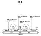
- FIG. 4 is a diagram for explaining the operation of the intake valve and the exhaust valve as an example of the in-cylinder temperature raising unit of the CPU (control unit) of the ECU 20 in this embodiment.
- TDC Top Dead Center
- BDC Bottom Dead Center
- the piston 18 moves up and down between the top dead center and the bottom dead center in the cylinder 15 of the engine. Reciprocate.
- a four-stroke / one-cycle engine will be described as an example, which undergoes four strokes during the engine operation cycle.
- the piston 18 In the expansion stroke, the air-fuel mixture ignited by the spark plug 17 burns, the combustion gas expands, and the piston 18 is pushed down to the bottom dead center. In the exhaust stroke, the piston 18 rises due to inertia and pushes the combustion gas out of the cylinder 15. In the intake stroke, the piston 18 descends and sucks the air-fuel mixture into the cylinder 15. In the compression stroke, the piston 18 rises to the top dead center and compresses the air-fuel mixture.
- the in-cylinder temperature raising part of the CPU (control part) of the ECU 20 of the present embodiment opens the exhaust valve 5d in the expansion stroke or the exhaust stroke and closes it before the top dead center of the exhaust stroke. Control the exhaust side.
- the intake valve 5c is opened in the intake stroke after the top dead center, and the variable valve timing mechanism 5a (intake side) is controlled so as to be closed in the intake stroke or the compression stroke.
- NVO period Negative Valve Overlap
- the gas in the exhaust stroke is trapped in the cylinder 15 and compressed, and the gas temperature rises.
- the cooling loss that is, the amount of heat transfer to the wall surface increases, and the temperature in the cylinder rises.
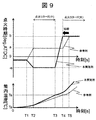
- FIG. 5 shows the ignition timing of the spark plug 17 in each cycle by the CPU (control unit) of the ECU 20 of this embodiment when one cycle of the engine shown in FIG. 4 is repeated and continuously performed for a certain period.
- the valve closing timing of the exhaust valve 5d, the valve opening timing of the intake valve 5c, and changes in the in-cylinder temperature in the cylinder 15 are shown.
- the value of the ECU 20 in the present embodiment is indicated by a thick line, and the value in the ECU 20 of the reference example to which the present embodiment is not applied is indicated by a dotted line.
- 0 is the top dead center
- the positive direction is the crank angle after the top dead center
- the negative direction is the crank angle before the top dead center. It is.
- a, b, c, and d in FIG. 5 are all positive real numbers.
- the engine is started at time 0, the ignition timing of the spark plug 17 is retarded at time T1, and warm-up is started.
- the temperature inside the cylinder 15 is low, and in order to avoid combustion instability, the ignition timing retard amount of the spark plug 17 is not set large, and at time T2, the ignition timing is set to a [deg. ATDC].
- the variable valve timing mechanism 5b (exhaust side) causes the exhaust valve 5d to move to 0 [deg. ATDC] or control to close the valve before and after that. That is, the valve closing timing (EVC, Exhaust Valve Close) is 0 [deg.], Which is the piston top dead center of the exhaust stroke. ATDC] or before and after that, and complete exhaust scavenging is performed.
- the variable valve timing mechanism 5a (intake side) controls the intake valve 5c to open immediately after EVC. That is, the valve opening timing (IVO, Intake Valve Open) is 0 [deg.], Which is the piston top dead center of the exhaust stroke. ATDC] or before and after that, and after exhausting is completely finished, intake of fresh air is started.
- the in-cylinder temperature is equal to the ambient temperature Ta at time 0, but when the in-cylinder temperature reaches the combustion stable temperature Ts at time T4, the ignition timing is further retarded, and at time T5, the ignition timing is set to b [deg. ATDC] to increase the exhaust gas temperature and accelerate the catalyst temperature rise.
- the CPU (control unit) of the ECU 20 of the present embodiment starts the engine at time 0, starts warming up at time T1, and performs ignition timing retard.
- the temperature inside the cylinder 15 is low immediately after the start of the cold engine, and the ignition timing retard amount is not set large to avoid combustion instability, and the ignition timing is set to a [deg. ATDC]. This is the same as the reference example.
- the in-cylinder temperature raising unit of the CPU (control unit) of the ECU 20 of the present embodiment performs ⁇ c before the top dead center of the exhaust stroke of the exhaust valve 5d by the variable valve timing mechanism 5b (exhaust side) at time T1. [Deg. [ATDC] is controlled to close.
- the variable valve timing mechanism 5a intake side moves the intake valve 5c to d [deg. [ATDC] is controlled to open. In this way, by controlling the variable valve timing mechanisms 5a and 5b so that the exhaust valve 5d is closed before the top dead center of the exhaust stroke and the intake valve 5c is opened after the top dead center of the exhaust stroke, An NVO period in which the intake and exhaust valves are simultaneously closed during the exhaust stroke is created.
- the CPU (control unit) of the ECU 20 gradually retards the ignition timing from time T1, and sets the ignition timing to a [deg. Before reaching ATDC], the variable valve timing mechanisms 5a and 5b are controlled so that the NVO period is formed by the in-cylinder temperature raising portion.
- the in-cylinder temperature is equal to the ambient temperature Ta at time 0, but the in-cylinder temperature rises more rapidly than in the reference example due to the in-cylinder temperature rise effect by providing the NVO period.
- the CPU (control unit) of the ECU 20 increases the ignition timing retard amount when the in-cylinder temperature Ts is reached or at a predetermined time T3, and the ignition timing is set to a [deg. B [deg.] Retarded further than ATDC].
- ATDC raises the exhaust gas temperature and accelerates the catalyst temperature rise.
- the ignition timing retard amount can be increased earlier than in the reference example.
- the gas temperature in the cylinder 15 rises, the amount of heat transfer to the wall surface increases, the temperature in the cylinder rises early, and the risk of combustion instability is reduced. For this reason, the ignition timing retard amount is increased at an early stage, the exhaust temperature is increased to accelerate the catalyst temperature rise, and the time until the catalyst is activated is shortened, so that the exhaust at the time of starting can be reduced.
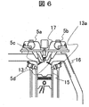
- FIG. 6 is a block diagram of the vicinity of the cylinder (dotted line A portion in FIG. 1) when the gas injection injector is arranged in the engine control apparatus according to the present embodiment.
- a gas injection injector 13 a that injects a gas such as air directly into the cylinder 15 is provided.
- the gas injector 13a is used to inject a gas, for example, air, into the cylinder 15 during the exhaust stroke, and to increase the volume of the gas confined inside the cylinder 15 during the NVO period.
- the temperature rises compared to when there is no gas injection.
- the ignition timing retard amount is increased, and at the time T4, the ignition timing is set to b [deg. ATDC] to increase the exhaust gas temperature and accelerate the catalyst temperature rise.
- Example 2 of the present invention will be described with reference to FIG.
- the basic engine configuration is the same as that of the first embodiment shown in FIG.
- the in-cylinder temperature raising part of the CPU (control part) of the ECU 20 is for raising the temperature in the cylinder by controlling the variable valve timing mechanism.
- FIG. 7 is a diagram for explaining the operation of the variable valve timing mechanism as an example of the in-cylinder temperature raising unit of the CPU (control unit) of the ECU 20 in this embodiment. Or the exhaust valve 5d is open.
- the engine compression ratio can be divided into two types: mechanical compression ratio and actual compression ratio.
- the mechanical compression ratio is a value obtained by dividing the in-cylinder volume at the piston bottom dead center by the in-cylinder volume at the piston top dead center, and is a compression ratio determined by the structure of the engine.
- the actual compression ratio is the value obtained by dividing the in-cylinder volume when the intake valve is closed by the in-cylinder volume at the top dead center of the piston. Can be small. For example, when the intake valve is closed after bottom dead center, part of the cylinder gas is blown back to the intake pipe, the volume in the cylinder is reduced, and the compression ratio of the cylinder gas is reduced.
- the mechanical compression ratio of a gasoline engine is approximately 10 to 14. In the present embodiment, the mechanical compression ratio 12 will be described as an example.
- the valve closing timing IVC IVO, Intake Valve Close
- IVC Intake Valve Close
- the actual compression ratio decreases away from the dead center.
- the IVC is set at or near the bottom dead center
- the actual compression ratio increases to the mechanical compression ratio. Then, more torque than necessary is generated at the start, and engine vibration is likely to occur.
- the IVC is advanced to the middle of the intake stroke or retarded to the middle of the compression stroke, the actual compression ratio is too low, the mixture temperature decreases, and misfire tends to occur.
- the IVC is at a position where the actual compression ratio is about 10, that is, a position advanced or retarded by 30 deg to 60 deg from the bottom dead center from the intake stroke to the compression stroke.
- the IVC is set at a position delayed by 60 deg from the bottom dead center, and the position is maintained even after the engine is started.
- the in-cylinder temperature raising part of the CPU (control part) of the ECU 20 gradually retards the ignition timing from time T1 after the engine is started in FIG.
- the variable valve timing mechanisms 5a and 5b are controlled so as to form the NVO period, but the temperature inside the cylinder is raised by another method. More specifically, the in-cylinder temperature raising unit of the CPU (control unit) of the ECU 20 gradually retards the ignition timing from the time T1 after the engine is started in FIG. Before reaching ATDC], the intake valve 5c is controlled to close at or near the bottom dead center from the intake stroke to the compression stroke.
- the IVC of the intake valve 5c is set at or near the bottom dead center from the intake stroke to the compression stroke.
- IVC is set at a position delayed by 25 deg from the bottom dead center.
- the CPU (control unit) of the ECU 20 increases the ignition timing retard amount when reaching a predetermined in-cylinder temperature Ts or at a predetermined time T3, and sets the ignition timing at the time T4.
- ATDC raises the exhaust gas temperature and accelerates the catalyst temperature rise.
- the ignition timing retard amount can be increased earlier than in the reference example. Therefore, by increasing the ignition timing retard amount at an early stage, increasing the exhaust temperature to accelerate the catalyst temperature rise, and shortening the time until the catalyst is activated, the exhaust at the time of starting can be reduced.
- Example 3 of the present invention will be described with reference to FIG.
- the basic engine configuration is the same as that of the first embodiment shown in FIG.
- the in-cylinder temperature raising part of the CPU (control part) of the ECU 20 is for raising the temperature in the cylinder by controlling the variable compression ratio mechanism.
- FIG. 8 shows changes in the ignition timing of the spark plug 17 by the CPU (control unit) of the ECU 20 of the present embodiment, the mechanical compression ratio of the variable compression ratio mechanism, and the in-cylinder temperature in the cylinder 15.
- the value of the ECU 20 in the present embodiment is indicated by a thick line
- the value in the ECU 20 of the reference example to which the present embodiment is not applied is indicated by a dotted line.
- 0 is the top dead center
- the positive direction is the crank angle after the top dead center
- the negative direction is the crank angle before the top dead center.
- a and b in FIG. 5 are all positive real numbers.
- the variable compression ratio mechanism is a device that adjusts the stroke amount of the piston 18 and adjusts the mechanical compression ratio of the engine 100. As described above, if the actual compression ratio at the time of starting increases to the same mechanical compression ratio, more torque than necessary is generated, and engine vibration is likely to occur. Conversely, if the actual compression ratio is too low, the temperature of the air-fuel mixture decreases and misfires are likely to occur. In view of these, a general engine mechanical compression ratio ⁇ 1 is determined in consideration of the adjustment margin of the actual compression ratio by the variable valve timing mechanism.
- the in-cylinder temperature raising part of the CPU (control part) of the ECU 20 gradually retards the ignition timing from time T1 after the engine is started in FIG.
- the variable valve timing mechanisms 5a and 5b are controlled so as to form the NVO period, but the temperature inside the cylinder is raised by another method. More specifically, the in-cylinder temperature raising unit of the CPU (control unit) of the ECU 20 gradually retards the ignition timing from time T1 after the engine is started, and sets the ignition timing to a [deg. Before reaching ATDC], the variable compression ratio mechanism is controlled to increase the mechanical compression ratio from ⁇ 1 to ⁇ 2.
- variable compression ratio By adjusting the mechanical compression ratio using the variable compression ratio, it is possible to raise the temperature in the cylinder more rapidly.
- increasing the ignition timing retard amount earlier increasing the exhaust temperature to accelerate the temperature rise of the catalyst, and shortening the time until catalyst activation, it is possible to reduce the exhaust at the time of starting.
- Example 4 of the present invention will be described with reference to FIG.
- the operation of the CPU (control unit) of the ECU 20 having the in-cylinder temperature raising unit other than providing the NVO period will be described.
- an in-cylinder temperature raising part by changing the ignition timing is shown as the in-cylinder temperature raising means other than providing the NVO period.
- FIG. 8 shows changes in the ignition timing of the ignition plug 17 and the in-cylinder temperature in the cylinder 15 by the CPU (control unit) of the ECU 20 of the present embodiment.
- the value of the ECU 20 in the present embodiment is indicated by a thick line, and the value in the ECU 20 of the reference example to which the present embodiment is not applied is indicated by a dotted line.
- 0 is the top dead center
- the positive direction is the crank angle after the top dead center
- the negative direction is the crank angle before the top dead center.
- a, b, and e in FIG. 5 are all positive real numbers.
- the ignition timing is retarded.
- the ignition timing is set to a [deg. ATDC].
- the exhaust temperature is increased and the catalyst warm-up effect is obtained.
- the amount of heat to the exhaust (exhaust loss) out of the heat loss becomes dominant, and Since the heat transfer amount (cooling loss) is relatively lowered, the temperature rise in the cylinder is not accelerated.
- the in-cylinder temperature raising portion of the CPU (control unit) of the ECU 20 advances the ignition timing after the engine is started, for example, at time T1 when the ignition timing is retarded in the reference example.
- the spark plug 17 is controlled.
- Advance the ignition timing especially -e [deg. When set to [ATDC], the ignited air-fuel mixture is compressed, and the in-cylinder temperature at the compression top dead center is significantly increased as compared to when the ignition timing is retarded.
- the ignition timing retard amount is increased, and at the time T4, the ignition timing is set to b [deg. ATDC] to increase the exhaust gas temperature and accelerate the catalyst temperature rise.
- the ignition timing is not advanced at time T1, but immediately May be shifted to the catalyst warm-up operation.
- the ignition timing is advanced immediately after start-up and the temperature in the cylinder is rapidly raised, so that a larger ignition timing retard amount can be obtained earlier than in the reference example after the temperature rise in the cylinder.
- the exhaust gas temperature rises, the catalyst temperature rises, and the time until the catalyst is activated is shortened, so that the exhaust gas at the start can be reduced.
- this invention is not limited to the above-mentioned Example, Various modifications are included.
- the above-described embodiments have been described in detail for easy understanding of the present invention, and are not necessarily limited to those having all the configurations described.
- a part of the configuration of one embodiment can be replaced with the configuration of another embodiment, and the configuration of another embodiment can be added to the configuration of one embodiment.
Landscapes
- Engineering & Computer Science (AREA)
- Chemical & Material Sciences (AREA)
- Combustion & Propulsion (AREA)
- Mechanical Engineering (AREA)
- General Engineering & Computer Science (AREA)
- Theoretical Computer Science (AREA)
- Signal Processing (AREA)
- Electrical Control Of Ignition Timing (AREA)
- Combined Controls Of Internal Combustion Engines (AREA)
- Output Control And Ontrol Of Special Type Engine (AREA)
Priority Applications (3)
| Application Number | Priority Date | Filing Date | Title |
|---|---|---|---|
| US16/076,755 US10641186B2 (en) | 2016-02-26 | 2017-01-13 | Internal combustion engine control apparatus |
| CN201780006371.2A CN108884804B (zh) | 2016-02-26 | 2017-01-13 | 内燃机控制装置 |
| EP17755996.0A EP3421777B1 (de) | 2016-02-26 | 2017-01-13 | Verbrennungsmotorsteuerungsvorrichtung |
Applications Claiming Priority (2)
| Application Number | Priority Date | Filing Date | Title |
|---|---|---|---|
| JP2016035029A JP6626738B2 (ja) | 2016-02-26 | 2016-02-26 | 内燃機関制御装置 |
| JP2016-035029 | 2016-02-26 |
Publications (1)
| Publication Number | Publication Date |
|---|---|
| WO2017145554A1 true WO2017145554A1 (ja) | 2017-08-31 |
Family
ID=59685306
Family Applications (1)
| Application Number | Title | Priority Date | Filing Date |
|---|---|---|---|
| PCT/JP2017/000914 Ceased WO2017145554A1 (ja) | 2016-02-26 | 2017-01-13 | 内燃機関制御装置 |
Country Status (5)
| Country | Link |
|---|---|
| US (1) | US10641186B2 (de) |
| EP (1) | EP3421777B1 (de) |
| JP (1) | JP6626738B2 (de) |
| CN (1) | CN108884804B (de) |
| WO (1) | WO2017145554A1 (de) |
Families Citing this family (4)
| Publication number | Priority date | Publication date | Assignee | Title |
|---|---|---|---|---|
| CN111561401B (zh) * | 2019-09-27 | 2021-06-11 | 长城汽车股份有限公司 | 可变压缩比发动机的控制方法及装置 |
| JP7291656B2 (ja) * | 2020-03-30 | 2023-06-15 | 日立Astemo株式会社 | 内燃機関の制御装置 |
| CN113137310B (zh) * | 2021-04-29 | 2023-03-24 | 广西玉柴机器股份有限公司 | 一种天然气发动机冷机排放控制策略 |
| FR3142126A1 (fr) * | 2022-11-18 | 2024-05-24 | Renault S.A.S | Procédé de commande d’un moteur de véhicule automobile comprenant au moins un mode de réglage du moteur visant à augmenter la quantité de calories issues du moteur utilisée par un système de chauffage du véhicule |
Citations (6)
| Publication number | Priority date | Publication date | Assignee | Title |
|---|---|---|---|---|
| JP2004144101A (ja) * | 1998-03-25 | 2004-05-20 | Denso Corp | 内燃機関の制御装置 |
| JP2004176607A (ja) * | 2002-11-26 | 2004-06-24 | Mitsubishi Automob Eng Co Ltd | エンジン |
| JP2009127428A (ja) * | 2007-11-20 | 2009-06-11 | Toyota Motor Corp | 内燃機関の制御装置 |
| JP2009162187A (ja) * | 2008-01-09 | 2009-07-23 | Toyota Motor Corp | 内燃機関 |
| JP2009191649A (ja) * | 2008-02-12 | 2009-08-27 | Toyota Motor Corp | 内燃機関の制御装置 |
| JP2013525654A (ja) * | 2010-04-30 | 2013-06-20 | マツダ株式会社 | 火花点火式エンジンの制御方法及び火花点火式エンジン |
Family Cites Families (9)
| Publication number | Priority date | Publication date | Assignee | Title |
|---|---|---|---|---|
| JPH08291729A (ja) | 1995-04-20 | 1996-11-05 | Fuji Heavy Ind Ltd | 筒内直噴エンジンの制御方法 |
| JP3521790B2 (ja) * | 1998-03-25 | 2004-04-19 | 株式会社デンソー | 内燃機関の制御装置 |
| JP4172319B2 (ja) * | 2003-04-30 | 2008-10-29 | 三菱自動車エンジニアリング株式会社 | エンジンの可変バルブタイミング制御装置 |
| JP4677844B2 (ja) * | 2005-07-27 | 2011-04-27 | 日産自動車株式会社 | エンジンのバルブタイミング制御装置 |
| CN101960126B (zh) | 2007-11-13 | 2013-01-02 | 丰田自动车株式会社 | 用于内燃发动机的控制装置 |
| JP5472076B2 (ja) | 2010-12-20 | 2014-04-16 | トヨタ自動車株式会社 | 火花点火内燃機関 |
| JP2012172671A (ja) | 2011-02-24 | 2012-09-10 | Nippon Soken Inc | 内燃機関の制御装置 |
| JP2012184688A (ja) | 2011-03-04 | 2012-09-27 | Denso Corp | 内燃機関の触媒早期暖機制御装置 |
| US9239016B2 (en) * | 2012-09-10 | 2016-01-19 | Ford Global Technologies, Llc | Catalyst heating with exhaust back-pressure |
-
2016
- 2016-02-26 JP JP2016035029A patent/JP6626738B2/ja active Active
-
2017
- 2017-01-13 CN CN201780006371.2A patent/CN108884804B/zh active Active
- 2017-01-13 WO PCT/JP2017/000914 patent/WO2017145554A1/ja not_active Ceased
- 2017-01-13 US US16/076,755 patent/US10641186B2/en active Active
- 2017-01-13 EP EP17755996.0A patent/EP3421777B1/de active Active
Patent Citations (6)
| Publication number | Priority date | Publication date | Assignee | Title |
|---|---|---|---|---|
| JP2004144101A (ja) * | 1998-03-25 | 2004-05-20 | Denso Corp | 内燃機関の制御装置 |
| JP2004176607A (ja) * | 2002-11-26 | 2004-06-24 | Mitsubishi Automob Eng Co Ltd | エンジン |
| JP2009127428A (ja) * | 2007-11-20 | 2009-06-11 | Toyota Motor Corp | 内燃機関の制御装置 |
| JP2009162187A (ja) * | 2008-01-09 | 2009-07-23 | Toyota Motor Corp | 内燃機関 |
| JP2009191649A (ja) * | 2008-02-12 | 2009-08-27 | Toyota Motor Corp | 内燃機関の制御装置 |
| JP2013525654A (ja) * | 2010-04-30 | 2013-06-20 | マツダ株式会社 | 火花点火式エンジンの制御方法及び火花点火式エンジン |
Also Published As
| Publication number | Publication date |
|---|---|
| US10641186B2 (en) | 2020-05-05 |
| EP3421777A1 (de) | 2019-01-02 |
| CN108884804B (zh) | 2020-09-11 |
| JP2017150420A (ja) | 2017-08-31 |
| EP3421777B1 (de) | 2021-04-28 |
| JP6626738B2 (ja) | 2019-12-25 |
| US20190048807A1 (en) | 2019-02-14 |
| EP3421777A4 (de) | 2019-10-02 |
| CN108884804A (zh) | 2018-11-23 |
Similar Documents
| Publication | Publication Date | Title |
|---|---|---|
| US6651601B2 (en) | Control strategy for improving cold cranking, starting, and warm-up of an engine having a variable valve actuation mechanism | |
| JP5245733B2 (ja) | エンジンの排気浄化装置 | |
| JP6222193B2 (ja) | 内燃機関の制御装置 | |
| US20100300383A1 (en) | Methods and Systems for Engine Control | |
| JP3992016B2 (ja) | 予混合圧縮自着火式内燃機関の制御装置 | |
| JPH11324778A (ja) | 筒内噴射ガソリンエンジン | |
| JP3743414B2 (ja) | エンジンの始動装置 | |
| CN108884804B (zh) | 内燃机控制装置 | |
| JP3852389B2 (ja) | エンジンの始動装置 | |
| JP2000073803A (ja) | 筒内噴射ガソリンエンジン | |
| JP2016094828A (ja) | ガソリンエンジンの始動制御装置 | |
| CN110462204A (zh) | 内燃机的控制装置 | |
| CN110730861B (zh) | 内燃机的控制方法及控制装置 | |
| JP4666162B2 (ja) | 内燃機関の燃料噴射制御装置 | |
| JP4419800B2 (ja) | エンジン始動装置 | |
| KR102059029B1 (ko) | 공기 충전량을 줄여 내연기관을 작동하기 위한 방법 및 장치 | |
| JP4285221B2 (ja) | 内燃機関 | |
| JP2519110B2 (ja) | オット―サイクルエンジン | |
| JP2004346854A (ja) | 内燃機関の圧縮着火運転の制御装置 | |
| JP5925099B2 (ja) | 内燃機関の制御装置 | |
| JP7276589B2 (ja) | 内燃機関の制御方法および制御装置 | |
| JP7256682B2 (ja) | 内燃機関の制御方法及び内燃機関の制御装置 | |
| JP2009041490A (ja) | 内燃機関の制御装置 | |
| JP6493508B1 (ja) | エンジンの始動制御装置 | |
| JP4682905B2 (ja) | 予混合圧縮自着火式内燃機関の制御装置 |
Legal Events
| Date | Code | Title | Description |
|---|---|---|---|
| NENP | Non-entry into the national phase |
Ref country code: DE |
|
| 121 | Ep: the epo has been informed by wipo that ep was designated in this application |
Ref document number: 17755996 Country of ref document: EP Kind code of ref document: A1 |