WO2017145573A1 - Dispositif d'évacuation d'air comprimé - Google Patents
Dispositif d'évacuation d'air comprimé Download PDFInfo
- Publication number
- WO2017145573A1 WO2017145573A1 PCT/JP2017/001335 JP2017001335W WO2017145573A1 WO 2017145573 A1 WO2017145573 A1 WO 2017145573A1 JP 2017001335 W JP2017001335 W JP 2017001335W WO 2017145573 A1 WO2017145573 A1 WO 2017145573A1
- Authority
- WO
- WIPO (PCT)
- Prior art keywords
- valve
- compressed air
- discharge
- port
- air
- Prior art date
- Legal status (The legal status is an assumption and is not a legal conclusion. Google has not performed a legal analysis and makes no representation as to the accuracy of the status listed.)
- Ceased
Links
Images


Classifications
-
- F—MECHANICAL ENGINEERING; LIGHTING; HEATING; WEAPONS; BLASTING
- F15—FLUID-PRESSURE ACTUATORS; HYDRAULICS OR PNEUMATICS IN GENERAL
- F15B—SYSTEMS ACTING BY MEANS OF FLUIDS IN GENERAL; FLUID-PRESSURE ACTUATORS, e.g. SERVOMOTORS; DETAILS OF FLUID-PRESSURE SYSTEMS, NOT OTHERWISE PROVIDED FOR
- F15B21/00—Common features of fluid actuator systems; Fluid-pressure actuator systems or details thereof, not covered by any other group of this subclass
- F15B21/12—Fluid oscillators or pulse generators
-
- F—MECHANICAL ENGINEERING; LIGHTING; HEATING; WEAPONS; BLASTING
- F16—ENGINEERING ELEMENTS AND UNITS; GENERAL MEASURES FOR PRODUCING AND MAINTAINING EFFECTIVE FUNCTIONING OF MACHINES OR INSTALLATIONS; THERMAL INSULATION IN GENERAL
- F16K—VALVES; TAPS; COCKS; ACTUATING-FLOATS; DEVICES FOR VENTING OR AERATING
- F16K21/00—Fluid-delivery valves, e.g. self-closing valves
Definitions
- the present invention relates to a compressed air discharge device that discharges compressed air supplied from an air supply source from a discharge port.
- Compressed air discharge devices are used to clean objects by blowing compressed air on objects such as workpieces and jigs, and to prevent charging of objects by blowing ionized air on objects.
- the compressed air discharge device used for such an application is connected to or mounted on an air ejection tool such as an air gun provided with a compressed air ejection port.
- Compressed air discharge devices that are connected to or mounted on an air gun include a type that continuously blows compressed air and a type that blows indirectly, and either type is selected depending on the application.
- Patent Document 1 An intermittent air discharge device is described in Patent Document 1, and an air ejection switching valve is described in Patent Document 2.
- Each of Patent Documents 1 and 2 can intermittently discharge compressed air to the injection port without using an electromagnetic valve.
- the intermittent air discharge device described in Patent Document 1 has a supply / discharge pilot chamber.
- the intermittent air discharge device When the main valve is switched to the discharge position by the pressure of the supply / discharge pilot chamber, the intermittent air discharge device is stored in the supply / discharge pilot chamber. The discharged air is discharged into the discharge flow path. Therefore, the amount of air discharged to the discharge flow path is set by the volume of the supply / discharge pilot chamber. For this reason, the flow rate of the air discharged by one intermittent air discharge device cannot be changed, and it is particularly difficult to increase the flow rate.
- this intermittent air discharge device When this intermittent air discharge device is mounted on the upstream side of the air gun, pilot air is discharged from the intermittent air discharge device and an exhaust sound is generated even when a trigger provided on the air gun, that is, a discharge operation switch is not operated. For this reason, this intermittent air discharge device must be mounted on the downstream side of the air gun, and there is a problem that the tip side of the air gun becomes heavy.
- the switching valve for air ejection described in Patent Document 2 has a mover that is arranged between two elastic valves to constitute a main valve, and compressed air from a compressed air pressure source is supplied to each elastic valve.
- the main valve chamber communicates with the air supply port.
- a movable child as an auxiliary valve is arranged, and when the air is discharged from the air supply port, the auxiliary valve is supplied from the air supply port through the bypass hole. Close the exhaust vent with air.
- the sub-valve is a two-port valve that switches the main valve between a discharge position and a discharge stop position by compressed air supplied from an air supply source, and discharges the compressed air from the exhaust port to the outside at the discharge stop position.
- the air ejection switching valve in which compressed air is intermittently discharged from the air supply port by constantly supplying compressed air to both sides of the main valve, the pressure of the supplied compressed air, bypass Since it is affected by the air resistance of the road and the cross-sectional area of the vent hole, the intermittent discharge operation characteristics are not reliable and unstable.
- the air ejection switching valve needs to change the original pressure supplied from the air supply source in order to change the discharge cycle.
- An object of the present invention is to provide a compressed air discharge device capable of enhancing the intermittent discharge operation characteristics of compressed air.
- the compressed air discharge device of the present invention is a compressed air discharge device that discharges compressed air supplied from an air supply source from a discharge port, and a discharge port that discharges compressed air from a supply port connected to the air supply source.
- Piston disposed in a pilot chamber to which compressed air is supplied to a discharge position for connecting the air supply port and the discharge port against a thrust force for pressing a blocking position for blocking communication with the port
- the sub-valve pilot chamber is communicated, and when the main valve is in the discharge position, a main pilot flow path that supplies compressed air to the sub-valve pilot chamber, and the pilot chamber and the output port are communicated.
- the main valve is switched between a discharge position for discharging primary compressed air from an air supply source to a discharge port and a blocking position for blocking discharge.
- the auxiliary valve that operates the main valve includes an output port that communicates with the piston of the main valve, an input port that is supplied with compressed air, and an exhaust port that communicates with the output port, and supplies compressed air to the pilot chamber.
- the air supply position for switching the main valve to the discharge position and the exhaust position for discharging the compressed air supplied to the pilot chamber to the outside are switched.
- the auxiliary valve has an auxiliary valve pilot chamber to which compressed air is supplied from the main pilot flow path when the main valve reaches the discharge position.
- the pilot chamber and the output port are communicated with each other through a supply / exhaust flow path, and when the sub valve is in the exhaust position, the air in the pilot chamber is discharged from the exhaust port.
- the main valve is switched to the discharge position when compressed air is supplied to the pilot chamber by the sub-valve, and is switched to the shut-off position when air in the pilot chamber is discharged, so that the compressed air is stably and reliably supplied from the discharge port. Discharged intermittently. Since an air ejection tool such as an air gun can be connected to the ejection port, the compressed air ejection device can be coupled upstream of the air ejection tool, and the operability of the air ejection tool can be improved.
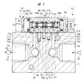
- FIG. 2 is an enlarged sectional view taken along line AA in FIG.
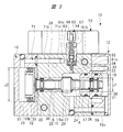
- FIG. 3 is an enlarged sectional view taken along line BB in FIG.
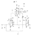
- FIG. 4 is a pneumatic circuit diagram of the compressed air discharge device shown in FIGS. 1 to 3.
- (A) is a discharge waveform diagram of compressed air in the intermittent discharge mode
- (B) is a discharge waveform diagram of compressed air in the continuous discharge mode.
- the compressed air discharge device 10 includes a port block 11 having a substantially rectangular parallelepiped shape.
- the main valve 12 is mounted on the outer surface 11a of the port block 11, and the sub valve 13 is mounted on the outer surface 11b that is perpendicular to the outer surface 11a.
- a bottomed supply port 14 is provided in the port block 11, the supply port 14 opens at one end face of the port block 11, and an air supply source 20 is not shown for supply piping or hose. It connects to the supply port 14 through the supply flow path which consists of.
- a bottomed discharge port 15 is provided in the port block 11, and the discharge port 15 opens at the other end face of the port block 11 and is coaxial with the supply port 14.
- the air gun G is connected to the discharge port 15, and the compressed air discharge device 10 is disposed on the upstream side of the air gun G.
- the compressed air discharge device 10 is arranged on the upstream side of the air gun G in the piping of the compressed air flow path, so the operator can hold the air gun G, so the compressed air to the object such as a workpiece or a tool Can be easily performed.
- the main valve 12 has a valve housing assembly 16 having a substantially rectangular parallelepiped shape.
- the valve housing assembly 16 includes a main body block 16a, a pilot block 16b attached to the one end face, and a pilot block 16c attached to the other end face of the main body block 16a.
- a large diameter hole 17 and a small diameter hole 18 are formed through the main body block 16a in the longitudinal direction, and the large diameter hole 17 and the small diameter hole 18 are coaxial.
- a receiving hole 19 having substantially the same diameter as the large diameter hole 17 is formed in the pilot block 16c.
- the small diameter hole 18 opens to one end face of the main body block 16a, and the large diameter hole 17 opens to the other end face of the main body block 16a.
- a sleeve 21 is fixed between the main body block 16 a and the pilot block 16 c, and the large-diameter hole 17 and the accommodation hole 19 are partitioned by the sleeve 21.
- a guide hole 22 having an inner diameter J1 is provided in the sleeve 21.
- a pilot hole 23 with a bottom is formed in the pilot block 16b, and an inner diameter J2 of the pilot hole 23 with a bottom is larger than an inner diameter J1 of the guide hole 22.
- the large-diameter hole 17 communicates with the supply port 14 through the communication hole 24, and the small-diameter hole 18 communicates with the discharge port 15 through the communication hole 25.
- the main valve shaft 26 is mounted in the valve housing assembly 16 so as to reciprocate in the axial direction.
- the main valve shaft 26 has a shaft portion 28 provided with a valve body 27, and the valve body 27 abuts on a valve seat 29 provided on a radial boundary surface between the large diameter hole 17 and the small diameter hole 18.
- the piston 31 is mounted in the pilot hole 23 so as to reciprocate in the axial direction, and the piston 31 is abutted against the end face of the shaft portion 28.
- a seal member 32 that contacts the inner peripheral surface of the pilot hole 23 is provided on the piston 31.
- a return piston 33 is provided on the shaft portion 28, and a seal member 34 that contacts the inner peripheral surface of the guide hole 22 is provided on the return piston 33. Further, a flange 35 is provided on the shaft portion 28, and a seal member 36 is provided on the flange 35.
- the piston 31 is provided at one end of the main valve shaft 26, the return piston 33 is provided at the other end, and the valve body 27 is provided at the central portion in the axial direction.
- the main valve shaft 26 is supported by a return piston 33 and a flange 35, and reciprocates in the valve housing assembly 16 in the axial direction.
- the pilot chamber 37 is surrounded by the piston 31 and the pilot hole 23, and the return pilot chamber 38 is surrounded by the return piston 33 and the accommodation hole 19.
- the return pilot chamber 38 is communicated with the communication hole 24 by a branch channel 39 formed in the valve housing assembly 16. Accordingly, the compressed air flowing into the supply port 14 from the air supply source 20 is always supplied to the return pilot chamber 38 via the communication hole 24.
- the piston 31 is abutted against the shaft portion 28, the piston 31 may be fixed to the shaft portion 28 with a screw member or the like.
- FIG. 3 corresponds to the air supply port A of the main valve 12 shown in FIG. 4, and the portion between the seal member 36 and the valve body 27 in the small diameter hole 18 shown in FIG. 3 is shown in FIG. This corresponds to the discharge port B of the valve 12.
- the supply port A communicates with the supply port 14 through the communication hole 24, and the discharge port B communicates with the discharge port 15 through the communication hole 25.
- the main valve shaft 26 is switched between a discharge position where the valve element 27 is separated from the valve seat 29 and a shut-off position where the valve element 27 contacts the valve seat 29.
- the main valve shaft 26 is located at the discharge position, the air supply port A and the discharge port B communicate with each other, and the primary compressed air from the air supply source 20 is discharged to the discharge port 15.
- the main valve shaft 26 is located at the shut-off position, the communication between the air supply port A and the discharge port B is shut off, and the discharge of compressed air from the discharge port 15 is stopped.
- the diameter of the piston 31 is larger than the diameter of the return piston 33. Therefore, when compressed air having substantially the same pressure is supplied to the pilot chamber 37 and the return pilot chamber 38, the thrust in the direction of separating the valve element 27 from the valve seat 29 blocks the thrust in the reverse direction, that is, the main valve shaft 26. It becomes larger than the thrust urging toward the position. Thus, the valve body 27 is separated from the valve seat 29 and the main valve shaft 26 is switched to the discharge position. On the other hand, when the compressed air is discharged from the pilot chamber 37 under the condition that the compressed air is supplied to the return pilot chamber 38, the valve element 27 contacts the valve seat 29 by the thrust of the compressed air applied to the return piston 33. The main valve shaft 26 is switched to the shut-off position. Thus, the pilot chamber 37 is a pilot chamber for discharge operation, and the return pilot chamber 38 is a pilot chamber for discharge stop operation.
- the return pilot chamber 38 is always in communication with the supply port 14 via the branch flow path 39, the large diameter hole 17, and the communication hole 24, so that compressed air is always supplied to the return pilot chamber 38.
- the main valve shaft 26 is constantly applied with a thrust in the return direction toward the shut-off position. Accordingly, by supplying compressed air to the pilot chamber 37, the valve element 27 is separated from the valve seat 29, and the main valve shaft 26 is switched to the discharge position. On the other hand, when the compressed air in the pilot chamber 37 is discharged, the valve body 27 comes into contact with the valve seat 29 and the communication between the air supply port A and the discharge port B is blocked.
- compressed air is always supplied to the return pilot chamber 38 as a return mechanism that urges the main valve shaft 26 to thrust in the return direction toward the shut-off position.
- a compression coil spring may be provided in the return pilot chamber 38 to apply a return direction thrust toward the valve seat 29 to the main valve shaft 26.
- the sub-valve 13 has a substantially rectangular parallelepiped valve housing assembly 41.
- the valve housing assembly 41 includes a main body block 41a, a pilot block 41b attached to the one end face, and a pilot block 41c attached to the other end face of the main body block 41a.
- a valve hole 42 is formed in the main body block 41a, and the valve hole 42 penetrates the main body block 41a in the longitudinal direction.
- the input port C, the output port D, and the exhaust port E are respectively formed in the main body block 41 a so as to communicate with the valve hole 42, and each port opens toward the outer surface 11 b of the port block 11.
- the outer surface 11b of the port block 11 functions as an attachment surface to which the auxiliary valve 13 is attached.
- the output port D is provided in the central portion of the main body block 41a in the axial direction, the input port C and the exhaust port E are disposed on both sides of the output port D in the axial direction, and the auxiliary valve 13 is a three-port valve.
- the pilot valve shaft 43 is mounted in the valve hole 42 so as to be capable of reciprocating in the axial direction.
- the pilot valve shaft 43 includes a shaft portion 45 and four pilot valve bodies 44, and sliding portions 46 a and 46 b are provided at both ends of the shaft portion 45.
- the sliding portions 46a and 46b are guided by the inner peripheral surface of the valve hole 42, and the shaft portion 45 reciprocates in the axial direction.
- the pilot valve shaft 43 has an air supply position where the input port C and the output port D communicate with each other, and an exhaust position where the communication between the input port C and the output port D is blocked and the output port D communicates with the exhaust port E. Switch to either.
- the seal member 47b provided on the pilot valve body 44 comes into contact with the valve seat 51 between the input port C and the output port D as shown in FIG.
- a seal member 47 a provided on the valve body 44 is separated from the valve seat 52 between the output port D and the exhaust port E.
- the seal member 47 a comes into contact with the valve seat 52 between the output port D and the exhaust port E, and the seal member 47 b is separated from the valve seat 51.
- a bottomed pilot hole 53 is formed in the pilot block 41c, and the inner diameter of the pilot hole 53 is K1.
- a pilot hole 54 with a bottom is formed in the pilot block 41b, and the inner diameter K2 of the pilot hole 54 is larger than the inner diameter K1 of the pilot hole 53.
- the sub valve piston 55 is slidably mounted in the pilot hole 54 in the axial direction, and the sub valve piston 55 is abutted against one end surface of the pilot valve shaft 43.
- the auxiliary valve return piston 56 is mounted in the pilot hole 53 so as to be slidable in the axial direction, and the auxiliary valve return piston 56 is abutted against the other end surface of the pilot valve shaft 43.
- the seal member 57 a is provided on the outer peripheral portion of the sub valve piston 55, and the seal member 57 b is provided on the outer peripheral portion of the sub valve return piston 56.
- the secondary valve pilot chamber 58 is surrounded by the secondary valve piston 55 and the pilot hole 54, and the secondary valve return pilot chamber 59 is surrounded by the secondary valve return piston 56 and the pilot hole 53.
- the auxiliary valve pilot chamber 58 urges the pilot valve shaft 43 to thrust in the direction toward the exhaust position.
- the auxiliary valve return pilot chamber 59 urges the pilot valve shaft 43 to thrust in the direction toward the air supply position.
- the diameter of the auxiliary valve piston 55 is larger than the diameter of the auxiliary valve return piston 56. Therefore, when compressed air having substantially the same pressure is supplied to the auxiliary valve pilot chamber 58 and the auxiliary valve return pilot chamber 59, the thrust applied to the auxiliary valve piston 55 is superior to the thrust applied to the auxiliary valve return piston 56.
- the pilot valve shaft 43 is biased to the exhaust position against the thrust force biased to the air supply position, and the pilot valve body 44 is brought into contact with the valve seat 51. Thereby, the pilot valve shaft 43 is switched to the exhaust position.
- the pilot valve is driven by the thrust in the return direction applied to the sub-valve return piston 56.
- the body 44 contacts the valve seat 52, and the pilot valve shaft 43 is switched to the air supply position.
- auxiliary valve return pilot chamber 59 Since the auxiliary valve return pilot chamber 59 is always in communication with the supply port 14 as will be described later, thrust is always applied to the auxiliary valve return piston 56, and the pilot valve shaft 43 returns to the supply position. Directional thrust is always applied. Accordingly, when compressed air is supplied to the auxiliary valve pilot chamber 58, the pilot valve shaft 43 is positioned at the exhaust position. When the compressed air in the auxiliary valve pilot chamber 58 is exhausted, the pilot valve shaft 43 is positioned at the supply position.
- auxiliary valve 13 In the auxiliary valve 13 shown in FIG. 2, compressed air is always supplied to the auxiliary valve return pilot chamber 59 as a return mechanism that urges the pilot valve shaft 43 to thrust in the return direction toward the air supply position.
- a compression coil spring may be provided in the auxiliary valve return pilot chamber 59 to always apply a thrust toward the air supply position to the pilot valve shaft 43.
- An air supply passage 61 is provided between the supply port 14 and the input port C, and compressed air supplied from the air supply source 20 is supplied to the input port C.
- the communication hole 24 communicating with the supply port 14 and the air supply channel 61 communicate with each other through a channel (not shown).
- a throttle hole 61a is formed in the main body block 16a, and the throttle hole 61a communicates with a throttle valve mounting hole 61b having a larger diameter.
- the throttle valve mounting hole 61 b communicates with a communication hole 61 c extending from the main body block 16 a to the port block 11.
- the communication hole 61c communicates with an air supply hole 61d that opens to the outer surface 11b, and the air supply hole 61d communicates with the input port C.
- the air supply passage 61 is formed by the throttle hole 61a, the throttle valve mounting hole 61b, the communication hole 61c, and the air supply hole 61d.
- an air supply throttle 62 composed of a variable throttle valve is mounted on the valve housing assembly 16.
- the air supply throttle 62 includes a valve case 63 attached to the throttle valve attachment hole 61 b and a screw shaft 64 screwed to the valve case 63, and the needle shaft 65 inserted into the throttle hole 61 a is the screw shaft 64. It is provided at the tip.
- An operation knob 66 is provided at the base end portion of the screw shaft 64, and a lock nut 67 is provided at the screw shaft 64.
- the air supply throttle 62 adjusts the flow rate of the compressed air flowing from the input port C to the output port D when the sub valve 13 is in the air supply position. The time until the main valve 12 is switched from the shut-off position to the air supply position is set by the air supply throttle 62.
- a supply / discharge channel 71 is provided between the output port D and the pilot chamber 37, and the output port D communicates with the pilot chamber 37 through the supply / discharge channel 71.
- a supply / discharge hole 71 a is opened in the outer surface 11 b and formed in the port block 11, and as shown in FIG. 3, a supply / discharge hole 71 b is formed in the valve housing assembly 16 of the main valve 12.
- the supply / discharge hole 71b communicates with the pilot chamber 37.
- Both supply / discharge holes 71a and 71b communicate with each other through a communication hole 71c formed in the port block 11 and the main body block 16a.
- the supply / discharge channel 71 is formed by the supply / discharge hole 71a, the supply / discharge hole 71b, and the communication hole 71c. Therefore, when the auxiliary valve 13 is in the supply position, the primary air from the air supply source 20 is supplied to the pilot chamber 37.
- a main pilot flow path 72 is provided between the discharge port 15 and the auxiliary valve pilot chamber 58.
- the main pilot flow path 72 supplies the compressed air to the sub valve piston 55.
- a pilot hole 72 a that opens to the outer surface 11 b is formed in the port block 11, and the pilot hole 72 a communicates with the discharge port 15 through the communication hole 25.
- a pilot hole 72 b communicating with the pilot hole 72 a is formed in the valve housing assembly 41 of the sub valve 13. The pilot hole 72 b opens into the auxiliary valve pilot chamber 58.
- the main pilot flow path 72 is formed by the pilot hole 72a and the pilot hole 72b.
- a secondary pilot channel 73 is provided between the supply port 14 and the secondary valve return pilot chamber 59.
- the compressed air supplied from the air supply source 20 is supplied to the auxiliary valve return piston 56 via the auxiliary pilot flow path 73.
- a pilot hole 73 a that opens in the outer surface 11 b is formed in the port block 11, and the pilot hole 73 a communicates with the supply port 14.
- a pilot hole 73 b communicating with the pilot hole 73 a is formed in the valve housing assembly 41.
- the pilot hole 73 b opens to the auxiliary valve return pilot chamber 59.
- the sub pilot flow path 73 is formed by the pilot hole 73a and the pilot hole 73b.
- the exhaust port E communicates with the outside of the port block 11 through an exhaust passage 74 formed in the port block 11.
- An exhaust hole 74 a that communicates with the exhaust port E opens in the outer surface 11 b and is formed in the port block 11, and an exhaust hole 74 b that communicates with the exhaust hole 74 a opens in the outer surface 11 c of the port block 11.
- the outer surface 11c where the exhaust hole 74b opens is a surface opposite to the outer surface 11a as shown in FIG. 1, and is exposed to the outside.
- An exhaust throttle 75 which is an exhaust throttle hole whose inner diameter is smaller than that of the exhaust hole 74a, is provided in the exhaust hole 74b.
- the amount of exhaust air throttle by the exhaust throttle 75 is constant, and the exhaust throttle 75 is a fixed throttle.
- the exhaust throttle 75 sets a time until the compressed air in the pilot chamber 37 is discharged to the outside.
- the exhaust throttle 75 is not limited to a fixed throttle, and may be a variable throttle.
- FIG. 4 is a pneumatic circuit diagram of the compressed air discharge device 10 shown in FIGS.
- a supply flow path 76 is connected to the supply port 14, and compressed air is supplied from the air supply source 20 to the air supply port A of the main valve 12 through the supply flow path 76.
- the air supply source 20 includes a compressor that generates compressed air, an accumulator that stores the compressed air, a pressure regulating valve that adjusts the pressure of the compressed air supplied to the supply flow path 76, that is, the primary side air, and the like.
- the compressed air supplied to the port 14 is set to an arbitrary pressure.
- a mode switching valve 77 is provided between the exhaust passage 74 and the atmosphere opening, and the exhaust passage 74 is opened and closed by the mode switching valve 77.
- the mode switching valve 77 is provided downstream of the exhaust throttle 75 in the exhaust passage 74.
- the mode switching valve 77 is manually operated by an operator and is switched between a discharge state in which compressed air is discharged from the exhaust passage 74 to the outside and a stop state in which discharge is stopped.
- the mode switching valve 77 is switched to an open state in which compressed air is discharged from the exhaust passage 74, the compressed air discharge device 10 is set to the intermittent discharge mode, and the exhaust passage 74 is closed and discharged. When stopped, the compressed air discharge device 10 is set to the continuous discharge mode.
- the compressed air discharge device 10 shown in FIG. 4 includes a mode switching valve 77 and can be switched between an intermittent discharge mode and a continuous discharge mode. However, in the form in which the mode switching valve 77 is not provided, the compressed air discharge device has only the intermittent discharge mode.
- the discharge operation valve 81 is, for example, a trigger switch for an air gun G.
- the trigger switch 81 a shown in FIG. 4 When the trigger switch 81 a shown in FIG. 4 is operated, compressed air is ejected from the ejection port 82.
- the main valve 12 when compressed air is supplied from the air supply source 20 to the supply flow path 76, the compressed air is supplied to the return pilot chamber 38 of the main valve 12 via the branch flow path 39. Thereby, the main valve 12 is switched to the cutoff position M1. Further, the sub valve 13 is switched to the air supply position P ⁇ b> 2 by the compressed air supplied to the sub valve return pilot chamber 59 via the sub pilot flow path 73. Compressed air is supplied to the input port C of the auxiliary valve 13 through the air supply passage 61. Since the auxiliary valve 13 is switched to the air supply position P ⁇ b> 2, the compressed air flows from the input port C to the output port D and is supplied to the pilot chamber 37. When compressed air is supplied to the pilot chamber 37, the main valve 12 is switched to the discharge position M2. The time until switching from the blocking position M1 to the discharge position M2 is set by the throttle amount of the air supply throttle 62.
- the main valve 12 when the main valve 12 is switched to the shut-off position M1 and the discharge position M2 by the sub valve 13 a plurality of times, the residual pressure inside the sub valve pilot chamber 58 and the like is increased, and the sub valve 13 The position of the exhaust position P1 is held by the residual pressure in the flow path 72 and the auxiliary valve pilot chamber 58.
- the auxiliary valve pilot chamber 58, the main pilot flow path 72, and the discharge flow path 78 are switched to the auxiliary valve pilot chamber 58, etc. A certain amount of compressed air is filled.
- the main valve 12 When predetermined compressed air is filled in the auxiliary valve pilot chamber 58 and the like, the main valve 12 is in the shut-off position M1, and the auxiliary valve 13 is stopped in the filling completion state, which is the exhaust position P1. This filling operation is the same even in a mode in which the mode switching valve 77 is not provided.
- the sub valve 13 is switched once to supply the compressed air to the inside of the device.
- the filling operation ends.
- the auxiliary valve 13 is in the state of holding the exhaust position P1 due to the residual pressure of the auxiliary valve pilot chamber 58 of the auxiliary valve 13 by the charging operation, the compressed air discharge device 10 enters a standby state. Thereby, the compressed air discharge apparatus 10 will be in the state which can eject compressed air with respect to a target object.
- the intermittent discharge mode is set, the main valve 12 maintains the state where it is in the cutoff position M1.
- the main valve 12 maintains the state where the discharge position M2 is reached.
- the intermittent discharge mode is set by the discharge mode switching valve 77 of the compressed air, and when the push button 81a of the discharge operation valve 81 is operated in the standby state, the auxiliary valve pilot chamber 58 is discharged from the discharge passage 78. The residual pressure air is ejected from the ejection port 82 onto the object.
- the auxiliary valve 13 is switched from the exhaust position P1 to the air supply position P2 due to the pressure drop in the auxiliary valve pilot chamber 58.
- the primary air is supplied to the pilot chamber 37 of the main valve 12.
- the main valve 12 is switched to the discharge position M2, and the air supply port A and the discharge port B of the main valve 12 communicate with each other.
- primary air from the air supply source 20 is discharged to the discharge port 15, and compressed air is discharged from the discharge port 82 of the discharge operation valve 81 through the discharge flow path 78.
- Discharge (ON) Time When the main valve 12 is switched to the discharge position M2, the primary side air is supplied to the secondary valve pilot chamber 58, and the secondary valve 13 is switched to the exhaust position P1.
- the discharge flow path 78 has resistance to the air flow, so that the pressure in the auxiliary valve pilot chamber 58 located upstream increases.
- the compressed air in the pilot chamber 37 is discharged to the atmosphere from the exhaust flow path 74 via the open mode switching valve 77, and the main valve 12 is switched to the cutoff position M1.
- the time during which the compressed air passes through the exhaust passage 74 that is, the discharge time, is set by the exhaust throttle 75 as a fixed throttle. Therefore, the time until the main valve 12 is switched from the discharge position M2 to the shut-off position M1, that is, the ON time during which the primary side air is ejected from the ejection port 82 of the discharge operation valve 81 is set by the opening of the exhaust throttle 75.
- the [3] Discharge stop (OFF) time When the main valve 12 is switched to the shut-off position M1, the compressed air in the sub-valve pilot chamber 58 is ejected from the ejection port 82, and the pressure in the sub-valve pilot chamber 58 is reduced.
- the valve 13 is switched from the exhaust position P1 to the supply position P2.
- the primary air is supplied to the pilot chamber 37 via the air supply passage 61 and the supply / exhaust passage 71, and the main valve 12 is switched from the cutoff position M1 to the discharge position M2.
- the time during which the compressed air passes through the air supply passage 61 and is supplied to the pilot chamber 37 that is, the air supply time is set by the air supply throttle 62.
- the time until the main valve 12 is switched from the shut-off position M1 to the discharge position M2, that is, the OFF time during which the jet of compressed air is stopped from the jet outlet 82 is set by the air supply throttle 62.
- the state returns to the compressed air discharge state of [1] described above.
- the primary air supplied from the air supply source 20 is intermittently, that is, turned on and off in a pulsed manner and discharged from the ejection port 82.
- the auxiliary valve 13 which is a three-port valve
- the primary side air is supplied to the pilot chamber 37 of the main valve 12 and the main valve 12 is switched to the discharge position.
- the sub valve 13 is switched to the exhaust position
- the air in the pilot chamber 37 of the main valve 12 is exhausted to the outside, and the main valve 12 is switched to the cutoff position. Accordingly, the main valve 12 is actuated by the compressed air supplied to the pilot chamber 37 via the sub valve 13, and the intermittent discharge operation can be performed stably and reliably, and the discharge operation characteristics can be improved.
- FIG. 5A is a discharge waveform diagram of compressed air in the intermittent discharge mode. Under the state where the intermittent discharge mode is set by the mode switching valve 77, the compressed air is discharged from the discharge port 15 until the push button, that is, the trigger switch 81a is returned, while repeatedly discharging and stopping the discharge of the compressed air. .
- the discharge time T ⁇ b> 1 in FIG. 5A is set to a constant value according to the throttle amount of the exhaust throttle 75.
- the discharge stop time T ⁇ b> 2 can be changed by the supply air throttle 62.
- the main valve 12 When primary air is supplied to the pilot chamber 37, the main valve 12 is switched to the discharge position M2, and the air supply port A and the discharge port B of the main valve 12 communicate with each other. Thereby, primary air from the air supply source 20 is discharged to the discharge port 15, and compressed air is discharged from the discharge port 82 via the discharge flow path 78.
- the main valve 12 When the main valve 12 is switched to the discharge position M2, the primary side air is supplied to the secondary valve pilot chamber 58, and the secondary valve 13 is switched to the exhaust position P1. Even when switched to the exhaust position P1, the exhaust flow path 74 is closed by the mode switching valve 77, so the compressed air in the pilot chamber 37 is not discharged to the outside. Therefore, the main valve 12 maintains the state of the discharge position M2, and the primary air is continuously ejected from the ejection port 82.
- FIG. 5B is a discharge waveform diagram of compressed air in the continuous discharge mode. Under the state where the mode switching valve 77 is set to the continuous discharge mode, the compressed air is continuously discharged from the discharge port 15. Continuous ejection is continued until the operation of the push button 81a is released.
- the compressed air discharge device 10 enters the continuous discharge mode in which the compressed air is continuously discharged to the discharge port 15. Is set.
- the sub valve 13 is fixed at the exhaust position P1, and the pilot chamber 37 is supplied with compressed air having the same pressure as that of the return pilot chamber 38. Since the diameter of the piston 31 in the pilot chamber 37 is larger than the diameter of the return piston 33 in the return pilot chamber 38, the thrust of the piston 31 is larger than the thrust of the return piston 33. Thereby, the main valve 12 maintains the state switched to the discharge position M2.
- the compressed air discharge device 10 is set to the intermittent discharge mode in which the compressed air is discharged to the discharge port 15 intermittently, that is, in a pulse shape.
- the intermittent discharge mode when the sub-valve 13 is switched to the air supply position P2, the pilot chamber 37 is supplied with compressed air having the same pressure as that of the return pilot chamber 38.
- the main valve 12 is switched to the discharge position M2, and compressed air is discharged from the discharge port 15.
- the sub valve 13 is switched to the exhaust position P1
- the compressed air in the pilot chamber 37 is discharged to the outside.
- the main valve 12 is switched to the cutoff position M1, and the discharge of the compressed air from the discharge port 15 is stopped.
- the sub-valve 13 operates by alternately repeating the exhaust position P1 and the air supply position P2, whereby the compressed air is intermittently discharged to the discharge port 15. In this manner, the compressed air discharge device 10 is switched between the intermittent discharge mode and the continuous discharge mode by the mode switching valve 77.
- the mode switching valve 77 is mounted on the outer surface 11c of the port block 11 directly or through a pipe or the like. As shown in FIG. 2, in the form in which the exhaust throttle 75 is formed in the port block 11, the compressed air throttled by the exhaust throttle 75 passes through the exhaust passage 74 between the exhaust throttle 75 and the mode switching valve 77. To the mode switching valve 77. However, the mode switching valve 77 may be mounted in communication with the exhaust hole 74 b without providing the exhaust throttle 75 in the exhaust hole 74 b of the port block 11. An exhaust throttle 75 including a fixed throttle is provided in the path, the discharge port, or the exhaust flow path 74. As a form of the fixed throttle, a plurality of types of screw members or mode switching valves 77 having different inner diameters may be provided, and these members may be replaced so that the throttle amount can be changed in a plurality of stages.
- the time during which compressed air is discharged from the discharge port 15, that is, the ON time is set by the inner diameter of the exhaust throttle 75 serving as an exhaust throttle.
- the time during which discharge is stopped is set by the ventilation area between the throttle hole 61 a and the needle shaft 65. This ventilation area is adjusted steplessly by a variable throttle valve as the supply throttle 62.
- the discharge flow path 78 is connected to the discharge port 15, and the compressed air discharged from the discharge port B of the main valve 12 is discharged to the discharge flow path 78.
- a discharge operation valve 81 is provided in the discharge flow path 78.
- the discharge operation valve 81 is a trigger switch for the air gun G.
- the discharge operation valve 81 is manually operated to an ejection position where the compressed air discharged from the discharge port B is ejected from the ejection port 82 and a stop position where the ejection is stopped.
- the push button 81a of the discharge operation valve 81 is pushed in by the operator, the discharge operation valve 81 is switched to the ejection position.
- the discharge operation valve 81 is returned to the stop position by the spring force.
- FIG. 6 is a pneumatic circuit showing a compressed air discharge device 10a which is a modified example.
- members that are the same as those shown in FIG. 4 are given the same reference numerals.
- the main valve 12 of the compressed air discharge device 10 described above is a two-port valve having an air supply port A and a discharge port B, whereas the main valve 12a shown in FIG. A three-port valve having B and a communication port F.
- a supply flow path 76 is connected to the air supply port A
- a discharge flow path 78 is connected to the discharge port B
- an air supply flow path 61 is connected to the communication port F.
- the main valve 12a is switched to either the cutoff position M1 or the discharge position M2 in the same manner as the main valve 12 described above. In the blocking position M1, the communication between the air supply port A and the discharge port B is blocked, and the air supply port A is connected to the communication port F. On the other hand, when switched to the discharge position M2, the air supply port A communicates with the discharge port B and the communication port F is blocked.
- the primary air from the air supply source 20 is constantly supplied to the input port C of the sub valve 13 through the air supply passage 61.
- the compressed air discharge device 10 shown in FIG. On the other hand, in the compressed air discharge device 10a shown in FIG. 6, when the main valve 12a is at the shut-off position M1, the primary air is supplied to the input port C, and the main valve 12a is switched to the discharge position M2. Then, the communication between the air supply source 20 and the input port C is interrupted. When this communication is blocked, the primary air is supplied from the air supply port A of the main valve 12a to the sub valve pilot chamber 58 of the sub valve 13 via the discharge port B. Accordingly, since the auxiliary valve 13 is switched to the exhaust position P1, the compressed air discharge device 10a shown in FIG.
- FIG. 3 is a poppet type two-way valve, whereas the main valve 12 shown in FIG. 6 is a spool type three-way valve.
- FIG. 7 is a pneumatic circuit showing a compressed air discharge device 10b which is another modification.
- members that are the same as those shown in FIG. 4 are given the same reference numerals.
- the thrust in the direction toward the cutoff position M1 is constantly applied by the return spring 85.
- a return spring 85 as a return mechanism is mounted in the return pilot chamber 38 of the main valve 12 shown in FIG. 26 is energized.
- the spring force in the return direction by the return spring 85 is set to a value smaller than the thrust applied by the piston 31 to the main valve shaft 26 in the direction toward the discharge position M2. Therefore, when compressed air is supplied to the pilot chamber 37, the thrust in the direction toward the discharge position M2 is larger than the thrust for return that is biased toward the cutoff position M1 by the return spring 85. Is switched to the discharge position M2.
- auxiliary valve return spring 86 as a return mechanism is mounted in the auxiliary valve return pilot chamber 59 of the auxiliary valve 13 shown in FIG. 2, and a return thrust in the direction toward the air supply position P2. Is urged toward the pilot valve shaft 43 by the auxiliary valve return spring 86.
- the spring force in the return direction by the auxiliary valve return spring 86 is set to a value smaller than the thrust applied to the pilot valve shaft 43 in the direction toward the exhaust position P1 by the auxiliary valve piston 55.
- the return mechanism for biasing the thrust in the return direction toward the shut-off position M1 and the return for biasing the thrust in the return direction toward the air supply position P2 includes a form using a piston and a form using a spring member. Further, there is a form in which only one return mechanism of the main valve 12 and the sub valve 13 is used as a spring member.
- the supply throttle 62 is a variable throttle
- the exhaust throttle 75 is a fixed throttle.
- the compressed air discharge devices 10, 10a and 10b can change the discharge time of the compressed air from the discharge port 15. Become. If both the air supply throttle 62 and the exhaust throttle 75 are variable throttles, both the discharge time and the discharge stop time can be changed.
- the compressed air discharge devices 10, 10a, and 10b can be switched to either the intermittent discharge mode or the continuous discharge mode by the mode switching valve 77, it is possible to perform an optimal air ejection operation according to the type of the object. . Thereby, the versatility of the compressed air discharge device 10, 10a, 10b is improved. Further, since the primary air supplied from the air supply source 20 to the supply port 14 is ejected from the ejection port 82 via the discharge port 15, the pressure of the primary side air supplied to the supply port 14, that is, the original pressure is adjusted. Compressed air having an arbitrary pressure can be ejected from the ejection port 82.
- the mode switching valve 77 is also provided in the compressed air discharge devices 10a and 10b shown in FIG. 6 and FIG. 7, but the compressed air discharge devices 10a and 10b shown in FIG. 10, when the mode switching valve 77 is not provided, the compressed air discharge device only in the intermittent discharge mode is obtained.
- the compressed air discharge devices 10, 10a, and 10b are applied to an air gun for spraying compressed air onto an object. For example, ionized air is sprayed onto a workpiece or a tool.
- the compressed air discharge devices 10 and 10a can be applied to various air blowing tools such as devices.
- the present invention is applied to clean the object by blowing compressed air onto the object or to prevent charging of the object by blowing ionized air onto the object.
Landscapes
- Engineering & Computer Science (AREA)
- General Engineering & Computer Science (AREA)
- Mechanical Engineering (AREA)
- Chemical & Material Sciences (AREA)
- Analytical Chemistry (AREA)
- Physics & Mathematics (AREA)
- Fluid Mechanics (AREA)
- Multiple-Way Valves (AREA)
- Fluid-Driven Valves (AREA)
Abstract
L'invention concerne un dispositif d'évacuation d'air comprimé (10) qui comprend une soupape principale (12) et une soupape secondaire (13). La soupape principale (12) est commutée entre une position d'évacuation (M2), dans laquelle de l'air comprimé est évacué vers un orifice d'évacuation (B), et une position de blocage (M1), dans laquelle l'évacuation est bloquée. La soupape secondaire (13) est commutée entre une position d'alimentation en air (P2), dans laquelle de l'air comprimé est fourni à une chambre pilote (37) à travers un passage d'écoulement d'alimentation/évacuation (71), ce qui permet de commuter la soupape principale (12) à la position d'évacuation (M2), et une position d'évacuation d'air (P1), dans laquelle de l'air comprimé dans la chambre pilote (37) est évacué vers l'extérieur. L'air comprimé est évacué par intermittence d'une ouverture d'évacuation lorsque la soupape secondaire (13) est commutée entre la position d'alimentation en air et la position d'évacuation d'air.
Applications Claiming Priority (4)
| Application Number | Priority Date | Filing Date | Title |
|---|---|---|---|
| JP2016033013 | 2016-02-24 | ||
| JP2016-033013 | 2016-02-24 | ||
| JP2016048255A JP6578230B2 (ja) | 2016-02-24 | 2016-03-11 | 圧縮空気吐出装置 |
| JP2016-048255 | 2016-03-11 |
Publications (1)
| Publication Number | Publication Date |
|---|---|
| WO2017145573A1 true WO2017145573A1 (fr) | 2017-08-31 |
Family
ID=59685377
Family Applications (1)
| Application Number | Title | Priority Date | Filing Date |
|---|---|---|---|
| PCT/JP2017/001335 Ceased WO2017145573A1 (fr) | 2016-02-24 | 2017-01-17 | Dispositif d'évacuation d'air comprimé |
Country Status (1)
| Country | Link |
|---|---|
| WO (1) | WO2017145573A1 (fr) |
Cited By (1)
| Publication number | Priority date | Publication date | Assignee | Title |
|---|---|---|---|---|
| CN114364885A (zh) * | 2019-09-06 | 2022-04-15 | Smc 株式会社 | 气缸、顶侧端盖以及杆侧端盖 |
Citations (2)
| Publication number | Priority date | Publication date | Assignee | Title |
|---|---|---|---|---|
| JPH07190221A (ja) * | 1993-12-28 | 1995-07-28 | Ckd Corp | エア吐出装置 |
| JP2010000486A (ja) * | 2008-06-23 | 2010-01-07 | Sunx Ltd | 除電除塵装置 |
-
2017
- 2017-01-17 WO PCT/JP2017/001335 patent/WO2017145573A1/fr not_active Ceased
Patent Citations (2)
| Publication number | Priority date | Publication date | Assignee | Title |
|---|---|---|---|---|
| JPH07190221A (ja) * | 1993-12-28 | 1995-07-28 | Ckd Corp | エア吐出装置 |
| JP2010000486A (ja) * | 2008-06-23 | 2010-01-07 | Sunx Ltd | 除電除塵装置 |
Cited By (1)
| Publication number | Priority date | Publication date | Assignee | Title |
|---|---|---|---|---|
| CN114364885A (zh) * | 2019-09-06 | 2022-04-15 | Smc 株式会社 | 气缸、顶侧端盖以及杆侧端盖 |
Similar Documents
| Publication | Publication Date | Title |
|---|---|---|
| JP6562086B2 (ja) | 打込機 | |
| KR102190802B1 (ko) | 스위칭 밸브 및 간헐 송풍 건 | |
| JP6289358B2 (ja) | 間欠エア吐出装置 | |
| KR102274208B1 (ko) | 유체 제어 밸브 | |
| JP6578230B2 (ja) | 圧縮空気吐出装置 | |
| CN105189047A (zh) | 气动工具的低压关闭阀 | |
| TW201922352A (zh) | 壓縮流體吐出控制裝置 | |
| US10830555B2 (en) | Projectile launching system | |
| KR101762812B1 (ko) | 공압 실린더 유니트 | |
| WO2017145573A1 (fr) | Dispositif d'évacuation d'air comprimé | |
| US20040105760A1 (en) | Ejector with gas propulsion | |
| US6925695B2 (en) | Modular rivet tool | |
| RU2734590C9 (ru) | Устройство прерывистого генерирования воздуха | |
| WO2014080664A1 (fr) | Appareil de décharge d'air intermittent | |
| WO2016063499A1 (fr) | Dispositif de génération d'air intermittent | |
| WO2004072487A1 (fr) | Soupape de commande pour un verin pneumatique | |
| CN113710369A (zh) | 高压流体喷出装置 |
Legal Events
| Date | Code | Title | Description |
|---|---|---|---|
| NENP | Non-entry into the national phase |
Ref country code: DE |
|
| 121 | Ep: the epo has been informed by wipo that ep was designated in this application |
Ref document number: 17756015 Country of ref document: EP Kind code of ref document: A1 |
|
| 122 | Ep: pct application non-entry in european phase |
Ref document number: 17756015 Country of ref document: EP Kind code of ref document: A1 |