WO2017145658A1 - Circuit hydraulique d'engin de chantier - Google Patents
Circuit hydraulique d'engin de chantier Download PDFInfo
- Publication number
- WO2017145658A1 WO2017145658A1 PCT/JP2017/003245 JP2017003245W WO2017145658A1 WO 2017145658 A1 WO2017145658 A1 WO 2017145658A1 JP 2017003245 W JP2017003245 W JP 2017003245W WO 2017145658 A1 WO2017145658 A1 WO 2017145658A1
- Authority
- WO
- WIPO (PCT)
- Prior art keywords
- pressure
- flow rate
- control valve
- hydraulic pump
- rotation speed
- Prior art date
- Legal status (The legal status is an assumption and is not a legal conclusion. Google has not performed a legal analysis and makes no representation as to the accuracy of the status listed.)
- Ceased
Links
Images



Classifications
-
- B—PERFORMING OPERATIONS; TRANSPORTING
- B66—HOISTING; LIFTING; HAULING
- B66C—CRANES; LOAD-ENGAGING ELEMENTS OR DEVICES FOR CRANES, CAPSTANS, WINCHES, OR TACKLES
- B66C13/00—Other constructional features or details
- B66C13/18—Control systems or devices
- B66C13/20—Control systems or devices for non-electric drives
-
- B—PERFORMING OPERATIONS; TRANSPORTING
- B66—HOISTING; LIFTING; HAULING
- B66C—CRANES; LOAD-ENGAGING ELEMENTS OR DEVICES FOR CRANES, CAPSTANS, WINCHES, OR TACKLES
- B66C23/00—Cranes comprising essentially a beam, boom, or triangular structure acting as a cantilever and mounted for translatory of swinging movements in vertical or horizontal planes or a combination of such movements, e.g. jib-cranes, derricks, tower cranes
- B66C23/62—Constructional features or details
- B66C23/84—Slewing gear
- B66C23/86—Slewing gear hydraulically actuated
-
- F—MECHANICAL ENGINEERING; LIGHTING; HEATING; WEAPONS; BLASTING
- F15—FLUID-PRESSURE ACTUATORS; HYDRAULICS OR PNEUMATICS IN GENERAL
- F15B—SYSTEMS ACTING BY MEANS OF FLUIDS IN GENERAL; FLUID-PRESSURE ACTUATORS, e.g. SERVOMOTORS; DETAILS OF FLUID-PRESSURE SYSTEMS, NOT OTHERWISE PROVIDED FOR
- F15B11/00—Servomotor systems without provision for follow-up action; Circuits therefor
- F15B11/02—Systems essentially incorporating special features for controlling the speed or actuating force of an output member
- F15B11/04—Systems essentially incorporating special features for controlling the speed or actuating force of an output member for controlling the speed
- F15B11/05—Systems essentially incorporating special features for controlling the speed or actuating force of an output member for controlling the speed specially adapted to maintain constant speed, e.g. pressure-compensated, load-responsive
Definitions
- the present invention relates to a hydraulic circuit of a work machine.
- a working machine As represented by a crane, a revolving body and a traveling body are provided, a working unit is further provided on the revolving body, a work object is held in the working unit, and is transferred in the turning direction.
- a working machine In particular, in a working machine such as the above-described crane, since the work object is swung in a swingable state, transfer is performed, and thus an extremely delicate turning operation is required from the operator.
- Patent Document 1 As a prior art for further improving the safety of a hydraulic drive device for driving a work machine, one described in Patent Document 1 can be cited.
- a bypass line for directly connecting a tank is provided in an oil passage connecting a pump and an open center type directional control valve, and the flow rate through the meter-in throttle of the directional control valve is limited to a predetermined value or less. Because of this port, safe turning is possible according to the load of the suspended load.
- the value of the engine speed is not reflected in the differential pressure across the meter-in throttle of the directional control valve, and there is room for improvement in operability.
- the hydraulic circuit of the work machine includes a prime mover whose rotational speed is determined based on an operation command, a variable displacement hydraulic pump driven by the prime mover, and discharge oil from the variable displacement hydraulic pump.
- a hydraulic circuit for a work machine including a driven swing motor and a control valve for controlling pressure oil supplied from the variable displacement hydraulic pump to the swing motor, and a rotation speed signal representing the rotation speed of the prime mover
- a flow rate adjustment valve that adjusts the flow rate of pressure oil that is guided from the variable displacement hydraulic pump to the control valve.
- the flow rate adjustment valve includes the rotation rate signal generation unit. Based on the output rotational speed signal, the differential pressure across the control valve is set to a value corresponding to the rotational speed of the prime mover.
- the differential pressure before and after the meter-in throttle of the directional control valve reflects the value of the engine speed that changes based on the user's operation
- a hydraulic circuit for a work machine that provides an uncomfortable operational feeling is provided. can do.
- FIG. 1 is a schematic view of a crane 1.
- the crane 1 includes a lower traveling body 10 and an upper swing body 20.
- the lower traveling body 10 includes a pair of crawlers 11, a pair of crawler frames 12, and a pair of traveling hydraulic motors 13 that independently drive and control the crawlers 11.
- the upper swing body 20 is driven by the driving force of the swing frame 21, the engine 22 provided on the swing frame 21, the hydraulic pump 23 driven by the engine 22, the swing hydraulic motor 24, and the swing hydraulic motor 24.
- a drive mechanism 25 that drives the swing body to swing and a control valve unit 26 that controls the direction and flow rate of the pressure oil supplied to the swing hydraulic motor 24 are provided.
- a boom 31 that can be raised and lowered is installed on the upper swing body 20.
- a sheave (not shown) is provided at the tip of the boom 31, and a suspended load 33 is suspended from a hook (not shown) provided at the tip of a hoisting rope 32 that is hung around the sheave.
- the upper swing body 20 is driven by a swing hydraulic motor 24 in a desired direction in the forward and reverse directions.
- the hoisting rope 34 is connected to a pendant rope (not shown).
- the boom 31 moves up and down by retracting and lifting the hoisting rope 34 with a hoisting winch (not shown).
- the suspended load 33 is moved up and down by retracting and unwinding the hoisting rope 32 by a unillustrated hoisting winch.
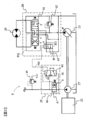
- FIG. 2 is a diagram showing the hydraulic circuit 2 of the crane 1.
- the hydraulic circuit 2 is supplied to a hydraulic pump 23 and a pilot pump 27 that are driven by the engine 22, a turning hydraulic motor 24 that is driven by pressure oil supplied from the hydraulic pump 23, and a turning hydraulic motor 24.
- a control valve unit 26 that controls the pressure oil, a pilot relief valve 28 that limits the upper limit of the discharge pressure of the pilot pump 27, and a rotation speed detection valve unit 29 that generates a command pressure PGR corresponding to the discharge flow rate of the pilot pump 27.
- the command pressure PGR is one of the valve switching control pressures when the upper limit rotational speed corresponding to the engine rotational speed of the turning hydraulic motor 24 is limited.
- the engine 22 drives the hydraulic pump 23 and the pilot pump 27. The number of revolutions of the engine 22 is controlled based on a depression amount of an unillustrated accelerator pedal operated by an operator.
- the hydraulic pump 23 is a variable displacement hydraulic pump.
- the discharge capacity of the hydraulic pump 23 is adjusted by a regulator controlled by a controller (not shown).
- the hydraulic pump 23 is driven by the engine 22 and pumps pressurized oil to the control valve unit 26.
- the pilot pump 27 is a fixed displacement hydraulic pump.
- the pilot pump 27 is driven by the engine 22 and pumps pressurized oil to the rotation speed detection valve unit 29.
- the control valve unit 26 includes a turning control valve (control valve) 41 that controls the flow direction and flow rate of the pressure oil supplied to the turning hydraulic motor 24, and a relief valve 42 that limits the upper limit of the discharge pressure of the hydraulic pump 23. And a flow rate adjusting valve 43 that adjusts the flow rate of the oil introduced into the turning control valve 41.
- the flow rate adjusting valve 43 is installed on an oil passage that branches off from an oil passage that connects the discharge port of the hydraulic pump 23 and the turning control valve 41 and is connected to the tank.
- the turning control valve 41 is at an arbitrary position between a neutral position O (initial position) shown in the figure, an A position on the left side in the figure, and a B position on the right side in the figure by a pilot pressure corresponding to the operation of a turning lever (not shown). Is switched to. Pressure oil having a flow rate corresponding to the operation amount of the turning control valve 41 is supplied to the hydraulic motor 24.
- the turning control valve 41 is an open center type control valve. When the turning control valve 41 is in the neutral position O, the pressure oil discharged from the hydraulic pump 23 passes through a bleed-off throttle (not shown) and is tanked. Return to.
- the turning control valve 41 moves in the direction of the A position or the B position, the opening area of the bleed-off restrictor is reduced, and the opening area of the meter-in restrictor is increased. To do.
- the pressure oil discharged from the hydraulic pump 23 is guided to the turning hydraulic motor 24 through the meter-in throttle.
- the turning control valve 41 is provided with a port for guiding a meter-in throttle downstream pressure, which will be described later, to the flow rate adjusting valve 43.
- the meter-in throttle downstream pressure is the tank pressure.
- the meter-in throttle downstream pressure is a pressure at which the discharge pressure of the hydraulic pump 23 is reduced due to the pressure loss of the meter-in throttle.
- the flow rate adjustment valve 43 changes between the closed position A and the open position B. In the open position B, part of the oil discharged from the hydraulic pump 23 bypasses to the tank. In the closed position A, the entire amount of oil discharged from the hydraulic pump 23 is introduced into the turning control valve 43.
- the switching position of the flow control valve 43 is controlled according to the following three pressures.
- the first pressure is the discharge pressure (meter-in throttle upstream pressure) PC1 of the hydraulic pump 23, and is guided to urge the flow rate adjustment valve 43 to the open position B side.
- the second pressure is the meter-in throttle downstream pressure PC2 of the turning control valve 41, and is guided to urge the flow rate adjustment valve 43 toward the closed position A.
- the third pressure is a command pressure PGR output from the rotation speed detection valve unit 29, and is guided to urge the flow rate adjustment valve 43 toward the closed position A.
- the flow rate adjusting valve 43 is opened and closed so that the differential pressure across the meter-in throttle of the turning control valve 41, that is, the difference between the discharge pressure PC1 of the hydraulic pump 23 and the meter-in throttle downstream pressure PC2 becomes a value corresponding to the command pressure PGR. Operates and functions as a pressure compensation valve.
- the flow rate control valve 43 When the discharge pressure PC1 of the hydraulic pump 23> the meter-in throttle downstream pressure PC2 + the command pressure PGR, the flow rate control valve 43 is switched to the B position, and a part of the discharge flow rate of the hydraulic pump 23 is bypassed from the flow rate control valve 43 to the tank.
- the upper limit of the turning speed is limited.
- the flow rate adjusting valve 43 is switched to the A position, and the total amount of the pressure oil discharged from the variable displacement hydraulic pump 23 is supplied to the turning control valve 41. Supplied.
- the differential pressure before and after the meter-in throttle is controlled to be equal to or less than a value proportional to the command pressure PGR.
- the command pressure PGR is substantially proportional to the engine speed.
- the turning load when the turning load is a predetermined value or more, for example, when the turning lever is fully operated, the turning speed does not exceed the upper limit value.
- this upper limit value does not depend on the engine speed.
- the upper limit value is changed according to the engine speed. Therefore, for example, when the turning lever is fully operated, the turning speed upper limit value when the engine speed is set in the high speed range, and the turning speed when the engine speed is set in the medium speed range The upper limit is made different.
- the work machine of the present invention is configured to vary the differential pressure across the direction control valve in accordance with the engine speed.
- the rotation speed detection valve unit 29 has a variable throttle 44 for generating a differential pressure corresponding to the discharge flow rate of the pilot pump 27 and a discharge pressure of the pilot pump 27 as a primary pressure, and the primary pressure is changed to a differential pressure across the variable throttle 44. And a pressure control valve 45 for generating a command pressure PGR regulated accordingly.
- the command pressure PGR increases or decreases according to the engine speed, and is used as a switching control pressure for the flow rate adjusting valve 43 as will be described later.
- the variable throttle 44 is switched between the open position A and the throttle position B based on the discharge pressure of the pilot pump 27 (upstream pressure of the variable throttle 44) and the downstream pressure of the variable throttle 44. Specifically, the discharge pressure of the pilot pump 27 is guided to switch the variable throttle 44 to the open position A side, and the downstream pressure of the variable throttle 44 is guided to switch the variable throttle 44 to the throttle position B side. .
- the spring 46 biases the variable throttle 44 so as to switch to the throttle position B side.
- the spring 46 has a spring constant such that the variable throttle 44 is switched to the open position A when pressure oil starts to be discharged from the hydraulic pump 27.
- the variable throttle 44 generates a differential pressure across the pilot pump 27 according to the discharge flow rate, and the open position A and the throttle position B so that the discharge flow rate of the pilot pump 27 and the differential pressure across the variable throttle 44 are proportional to each other.
- the opening area at a position between is set.
- the downstream pressure of the variable throttle 44 is defined by the pilot relief valve 28 so as to be approximately constant.
- the pressure control valve 45 switches between the position A and the position B based on the upstream pressure and the downstream pressure of the variable throttle 44.
- the upstream pressure of the variable throttle 44 is larger than the sum of the downstream pressure of the variable throttle 44 and the command pressure PGR, the pressure control valve 45 is switched to the position A side, and the command is obtained by guiding the upstream pressure of the variable throttle 44.
- Increase pressure PGR is provided by guiding the upstream pressure of the variable throttle 44.
- the pressure control valve 45 When the upstream pressure of the variable throttle 44 is smaller than the sum of the downstream pressure of the variable throttle 44 and the command pressure PGR, the pressure control valve 45 is switched to the position B side, and the command pressure PGR is reduced by being connected to the tank. Let That is, the command pressure PGR proportional to the differential pressure across the variable throttle 44 is generated using the downstream pressure of the variable throttle 44 as the primary pressure.
- the opening area A of the variable throttle 44 is set so that the discharge flow rate of the pilot pump 27 and the differential pressure across the variable throttle 44 have a proportional relationship.
- the relationship of the front-rear differential pressure ⁇ P of the variable throttle 22 is expressed by the following equation (3).
- A a ⁇ P (3)
- Expression (3) is substituted into Expression (2)
- the relationship between the discharge flow rate Qp of the pilot pump 27 and the differential pressure ⁇ P across the variable throttle 22 is expressed by the following Expression (4).
- the flow control valve 43 controls the opening degree of the flow control valve 43 so that the differential pressure before and after the meter-in throttle is equal to or less than the pressure proportional to the command pressure PGR. Therefore, the upper limit value of the flow rate that passes through the turning control valve 41 is a flow rate proportional to the engine speed due to the action of the flow rate control valve 43.
- the working machine that is, the hydraulic circuit 2 of the crane 1 includes an engine 22 as a prime mover whose rotation speed is determined based on an operation command, a variable displacement hydraulic pump 23 driven by the engine 22, and a variable displacement hydraulic pump 23.
- a swing motor 24 driven by the oil discharged from the engine, an open center control valve 41 for controlling the pressure oil supplied from the variable displacement hydraulic pump 23 to the swing motor 24, and a hydraulic pressure representing the rotational speed of the engine 22.
- a flow rate adjustment pressure that is a rotation speed signal that is, a rotation speed signal generation unit that generates a command pressure PGR, that is, a rotation speed detection valve unit 29, and a flow rate that adjusts the flow rate of pressure oil introduced from the variable displacement hydraulic pump 23 to the control valve 41.
- a control valve 43 sets the differential pressure across the control valve 41 to a value corresponding to the rotational speed of the engine 22 based on the command pressure PGR output from the rotational speed detection valve unit 29.
- the flow rate adjusting valve 43 discharges a part of the pressure oil discharged from the variable displacement hydraulic pump 23 to the tank based on the flow rate adjusting pressure output from the rotation speed detection valve unit 29.
- the flow rate adjustment valve 43 As the command pressure PGR is higher, the flow rate adjustment valve 43 is controlled to the closed side and the amount of oil that escapes to the tank decreases. That is, a part of the pressure oil discharged from the variable displacement hydraulic pump 23 is diverted to an oil passage other than the control valve 41, that is, a tank according to the engine speed. As a result, the flow rate adjustment valve 43 controls the differential pressure across the meter-in throttle so as to be a value proportional to the engine speed.
- the rotation speed detection valve unit 29 is configured to change the discharge pressure of the fixed displacement hydraulic pump 27 according to the front-rear differential pressure and the variable throttle 44 that generates the front-rear differential pressure by introducing the pressure oil discharged from the fixed displacement hydraulic pump 27.
- a pressure control valve 45 for converting to the command pressure PGR.
- the differential pressure across the meter-in throttle of the control valve 41 is set based on the command pressure PGR generated by the pressure control valve 45.
- the control valve 41 increases as the rotational speed of the engine 22 increases.
- the differential pressure across the meter-in throttle of the control valve increases, and the differential pressure across the meter-in throttle of the control valve decreases as the rotational speed of the engine 22 decreases. Therefore, the operator can control the torque for driving the turning hydraulic motor 24 by turning the engine control dial to increase or decrease the engine speed, and it is possible to provide a crane with better operability.
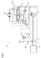
- FIG. 3 is a diagram illustrating a hydraulic circuit 2a according to the second embodiment. Except for the configuration downstream of the pilot pump 27, the second embodiment is the same as the first embodiment.
- the hydraulic circuit 2a of the second embodiment has a fixed throttle 44a to which the pressure oil discharged from the fixed displacement hydraulic pump 27 is guided.
- the upstream pressure of the fixed throttle 44a is input to the flow rate adjustment valve 43 via the oil passage 29a as the command pressure PGR.
- the upstream pressure of the fixed throttle 44a increases or decreases in proportion to the engine speed.
- the hydraulic circuit of the second embodiment that introduces this upstream pressure as the command pressure PGR into the control port of the flow rate adjustment valve 43 can obtain the same operational effects as those of the first embodiment.
- the rotation speed detection valve unit 29 since the rotation speed detection valve unit 29 does not exist, the linearity of the PGR with respect to the engine rotation speed is lost as in the first embodiment, but the fixed throttle Therefore, the configuration is simpler than that of the hydraulic circuit of the first embodiment.
- a rotation detector 50 for detecting the rotation speed of the engine, an electromagnetic valve 52 for generating a command pressure PGR, and an operation command is output to the electromagnetic valve 52 based on the output of the rotation detector 50.
- the point which is provided with the controller 51 which performs is mainly different from 1st Embodiment.
- FIG. 4 is a diagram illustrating the connection of the hydraulic circuit 2b and the electrical system in the third embodiment.
- a relief valve 28 and an electromagnetic valve 52 are connected to the discharge side oil passage of the pilot pump 27.
- the solenoid valve 52 includes a solenoid that operates based on a command from the controller 51.
- the solenoid valve 52 generates a command pressure PGR based on a command from the controller 51 using the discharge pressure of the pilot pump 27 as a primary pressure.
- the rotation detector 50 measures the number of revolutions of the engine 22 and outputs information on the number of revolutions to the controller 51 as an electrical signal.
- the controller 51 converts the scale of the electrical signal received from the rotation detector 50 and outputs it to the solenoid valve 52. That is, the rotation detector 50, the controller 51, and the electromagnetic valve 52 function as a rotation speed signal generation unit that generates a command pressure PGR that is information related to the rotation speed of the engine 22.
- the command pressure PGR generated by the electromagnetic valve 52 is generated as a pressure proportional to the engine speed, similarly to the flow rate adjustment pressure output from the pressure control valve 45 of the first embodiment. Therefore, the hydraulic circuit of the third embodiment that introduces the command pressure PGR generated in this way into the control port of the flow rate control valve 43 can obtain the same operational effects as those of the first embodiment. . In the hydraulic circuit of the third embodiment, it is not necessary to provide a throttle in the discharge path of the pilot pump 27, and energy loss of the pressure oil discharged from the pilot pump 27 can be suppressed.
- the command pressure PGR based on the rotation speed of the engine 22 measured by the rotation detector 50 is generated, and the command pressure PGR is input to the control port of the flow rate adjustment valve 43.
- the flow control valve 43 may include a solenoid, and the flow control valve 43 may be configured to operate based on an electrical signal output from the controller 51.
- FIG. 5 is a diagram illustrating a hydraulic circuit 2c and an electric system in a modification of the third embodiment.
- the solenoid valve 52 is omitted and the flow rate control valve 43 is changed to an electromagnetic flow rate control valve 43a.
- the discharge pressure (meter-in throttle upstream pressure) and the meter-in throttle downstream pressure of the hydraulic pump 23 are input to the two control ports of the flow control valve 43a.
- An electric signal proportional to the engine speed output from the controller 51 is applied to the solenoid 43s of the electromagnetic flow control valve 43a, and the solenoid 43s is an electromagnetic switch that switches the flow control valve 43a to the position A side. Give power.
- the electromagnetic urging force by this electric signal is a signal equivalent to the command pressure PGR. Therefore, the flow rate adjustment valve 43a has an opening degree so that the difference between the discharge pressure (meter-in throttle upstream pressure) of the hydraulic pump 23 and the meter-in throttle downstream pressure is equal to or less than the pressure proportional to the electrical signal output from the controller 51. Be controlled. Therefore, also in the modification of the third embodiment, the same operational effects as those of the first embodiment can be obtained.
Landscapes
- Engineering & Computer Science (AREA)
- Mechanical Engineering (AREA)
- Physics & Mathematics (AREA)
- Fluid Mechanics (AREA)
- General Engineering & Computer Science (AREA)
- Automation & Control Theory (AREA)
- Fluid-Pressure Circuits (AREA)
- Control And Safety Of Cranes (AREA)
- Jib Cranes (AREA)
Abstract
L'invention concerne un circuit hydraulique d'engin de chantier permettant d'obtenir une bonne sensation d'opération de rotation. Ce circuit hydraulique d'engin de chantier est pourvu : d'un moteur d'entraînement, dont la vitesse de rotation est déterminée sur la base d'une instruction de fonctionnement ; d'une pompe hydraulique à capacité variable entraînée par le moteur d'entraînement ; d'un moteur de rotation entraîné par l'huile déchargée par la pompe hydraulique à capacité variable ; et d'une soupape de commande du type à centre ouvert permettant de commander l'huile sous pression fournie par la pompe hydraulique à capacité variable au moteur de rotation et, dans une position initiale, d'effectuer une commande de telle sorte que l'huile déchargée par la pompe hydraulique à capacité variable est renvoyée vers un réservoir. Le circuit hydraulique d'engin de chantier est caractérisé : en ce qu'il est pourvu d'une unité de génération de signal de vitesse de rotation permettant de générer un signal de vitesse de rotation qui représente la vitesse de rotation du moteur d'entraînement et d'une soupape de réglage de débit permettant de régler le débit de l'huile sous pression guidée de la pompe hydraulique à capacité variable à la soupape de commande ; et en ce que la soupape de réglage de débit fait en sorte que la différence de pression dans la soupape de commande soit égale à une valeur correspondant à la vitesse de rotation du moteur d'entraînement en fonction du signal de vitesse de rotation fourni par l'unité de génération de signal de vitesse de rotation.
Applications Claiming Priority (2)
| Application Number | Priority Date | Filing Date | Title |
|---|---|---|---|
| JP2016034714A JP6491123B2 (ja) | 2016-02-25 | 2016-02-25 | 作業機械の油圧回路 |
| JP2016-034714 | 2016-02-25 |
Publications (1)
| Publication Number | Publication Date |
|---|---|
| WO2017145658A1 true WO2017145658A1 (fr) | 2017-08-31 |
Family
ID=59685614
Family Applications (1)
| Application Number | Title | Priority Date | Filing Date |
|---|---|---|---|
| PCT/JP2017/003245 Ceased WO2017145658A1 (fr) | 2016-02-25 | 2017-01-30 | Circuit hydraulique d'engin de chantier |
Country Status (2)
| Country | Link |
|---|---|
| JP (1) | JP6491123B2 (fr) |
| WO (1) | WO2017145658A1 (fr) |
Cited By (1)
| Publication number | Priority date | Publication date | Assignee | Title |
|---|---|---|---|---|
| CN109292629A (zh) * | 2018-10-26 | 2019-02-01 | 中船华南船舶机械有限公司 | 一种起重机液压回转系统 |
Families Citing this family (1)
| Publication number | Priority date | Publication date | Assignee | Title |
|---|---|---|---|---|
| CN114084802A (zh) * | 2021-11-19 | 2022-02-25 | 徐州建机工程机械有限公司 | 一种塔机多机构双闭环主从同步控制系统 |
Citations (2)
| Publication number | Priority date | Publication date | Assignee | Title |
|---|---|---|---|---|
| JPH11158939A (ja) * | 1997-11-27 | 1999-06-15 | Hitachi Constr Mach Co Ltd | 油圧制御装置 |
| JP2005265016A (ja) * | 2004-03-17 | 2005-09-29 | Kobelco Contstruction Machinery Ltd | 作業機械の油圧制御装置 |
-
2016
- 2016-02-25 JP JP2016034714A patent/JP6491123B2/ja not_active Expired - Fee Related
-
2017
- 2017-01-30 WO PCT/JP2017/003245 patent/WO2017145658A1/fr not_active Ceased
Patent Citations (2)
| Publication number | Priority date | Publication date | Assignee | Title |
|---|---|---|---|---|
| JPH11158939A (ja) * | 1997-11-27 | 1999-06-15 | Hitachi Constr Mach Co Ltd | 油圧制御装置 |
| JP2005265016A (ja) * | 2004-03-17 | 2005-09-29 | Kobelco Contstruction Machinery Ltd | 作業機械の油圧制御装置 |
Cited By (2)
| Publication number | Priority date | Publication date | Assignee | Title |
|---|---|---|---|---|
| CN109292629A (zh) * | 2018-10-26 | 2019-02-01 | 中船华南船舶机械有限公司 | 一种起重机液压回转系统 |
| CN109292629B (zh) * | 2018-10-26 | 2020-05-05 | 中船华南船舶机械有限公司 | 一种起重机液压回转系统 |
Also Published As
| Publication number | Publication date |
|---|---|
| JP2017150607A (ja) | 2017-08-31 |
| JP6491123B2 (ja) | 2019-03-27 |
Similar Documents
| Publication | Publication Date | Title |
|---|---|---|
| EP2241529B1 (fr) | Appareil de contrôle de freinage pour machine de travail de type à giration | |
| US5873245A (en) | Hydraulic drive system | |
| US9181070B2 (en) | Hydraulic driving apparatus for working machine | |
| CN104603468B (zh) | 工程机械的液压驱动装置 | |
| CN104379945B (zh) | 建筑机械的控制系统 | |
| CN111133204A (zh) | 工程机械 | |
| JP2015197185A (ja) | 作業機械の油圧制御装置 | |
| KR20200035951A (ko) | 쇼벨 | |
| JP2001323902A (ja) | 油圧駆動装置 | |
| US6438952B1 (en) | Hydraulic circuit device | |
| CN111356844A (zh) | 油压驱动系统 | |
| JP6491123B2 (ja) | 作業機械の油圧回路 | |
| JP3078947B2 (ja) | 流体圧アクチュエータの駆動制御装置 | |
| JP6393660B2 (ja) | 油圧回路 | |
| JP7124610B2 (ja) | 建設機械の油圧装置 | |
| JP4166604B2 (ja) | ウインチの速度制御装置およびクレーン | |
| JP2024045725A (ja) | クレーン | |
| JP2002265187A (ja) | 旋回制御装置 | |
| JP2019002558A (ja) | 旋回駆動装置、およびこれを備えた作業機械 | |
| JP6591370B2 (ja) | 建設機械の油圧制御装置 | |
| JP2555287B2 (ja) | 油圧制御装置 | |
| JPH0517961B2 (fr) | ||
| JP3705886B2 (ja) | 油圧駆動制御装置 | |
| JP6857152B2 (ja) | 作業機械の油圧回路 | |
| JP3594633B2 (ja) | 油圧駆動装置 |
Legal Events
| Date | Code | Title | Description |
|---|---|---|---|
| NENP | Non-entry into the national phase |
Ref country code: DE |
|
| 121 | Ep: the epo has been informed by wipo that ep was designated in this application |
Ref document number: 17756100 Country of ref document: EP Kind code of ref document: A1 |
|
| 122 | Ep: pct application non-entry in european phase |
Ref document number: 17756100 Country of ref document: EP Kind code of ref document: A1 |