WO2017145754A1 - Dispositif d'acquisition d'informations de degré d'usure, procédé d'acquisition d'informations de degré d'usure, véhicule, et programme - Google Patents
Dispositif d'acquisition d'informations de degré d'usure, procédé d'acquisition d'informations de degré d'usure, véhicule, et programme Download PDFInfo
- Publication number
- WO2017145754A1 WO2017145754A1 PCT/JP2017/004526 JP2017004526W WO2017145754A1 WO 2017145754 A1 WO2017145754 A1 WO 2017145754A1 JP 2017004526 W JP2017004526 W JP 2017004526W WO 2017145754 A1 WO2017145754 A1 WO 2017145754A1
- Authority
- WO
- WIPO (PCT)
- Prior art keywords
- vehicle
- power line
- wear
- laser sensor
- distance
- Prior art date
- Legal status (The legal status is an assumption and is not a legal conclusion. Google has not performed a legal analysis and makes no representation as to the accuracy of the status listed.)
- Ceased
Links
Images





Classifications
-
- B—PERFORMING OPERATIONS; TRANSPORTING
- B60—VEHICLES IN GENERAL
- B60M—POWER SUPPLY LINES, AND DEVICES ALONG RAILS, FOR ELECTRICALLY- PROPELLED VEHICLES
- B60M1/00—Power supply lines for contact with collector on vehicle
- B60M1/12—Trolley lines; Accessories therefor
- B60M1/28—Manufacturing or repairing trolley lines
-
- G—PHYSICS
- G01—MEASURING; TESTING
- G01B—MEASURING LENGTH, THICKNESS OR SIMILAR LINEAR DIMENSIONS; MEASURING ANGLES; MEASURING AREAS; MEASURING IRREGULARITIES OF SURFACES OR CONTOURS
- G01B11/00—Measuring arrangements characterised by the use of optical techniques
- G01B11/30—Measuring arrangements characterised by the use of optical techniques for measuring roughness or irregularity of surfaces
-
- G—PHYSICS
- G01—MEASURING; TESTING
- G01C—MEASURING DISTANCES, LEVELS OR BEARINGS; SURVEYING; NAVIGATION; GYROSCOPIC INSTRUMENTS; PHOTOGRAMMETRY OR VIDEOGRAMMETRY
- G01C3/00—Measuring distances in line of sight; Optical rangefinders
- G01C3/22—Measuring distances in line of sight; Optical rangefinders using a parallactic triangle with variable angles and a base of fixed length at, near, or formed by the object
-
- G—PHYSICS
- G01—MEASURING; TESTING
- G01B—MEASURING LENGTH, THICKNESS OR SIMILAR LINEAR DIMENSIONS; MEASURING ANGLES; MEASURING AREAS; MEASURING IRREGULARITIES OF SURFACES OR CONTOURS
- G01B11/00—Measuring arrangements characterised by the use of optical techniques
- G01B11/24—Measuring arrangements characterised by the use of optical techniques for measuring contours or curvatures
- G01B11/245—Measuring arrangements characterised by the use of optical techniques for measuring contours or curvatures using a plurality of fixed, simultaneously operating transducers
Definitions
- the present invention relates to a wear degree information acquisition device, a wear degree information acquisition method, a vehicle, and a program.
- This application claims priority based on Japanese Patent Application No. 2016-031397 for which it applied to Japan on February 22, 2016, and uses the content here.
- Patent Document 1 When a vehicle travels with power supplied from a power line such as an electric railway or a new transportation system, it is necessary to detect the wear of the power line and replace the power line.
- a power line such as an electric railway or a new transportation system
- the trolley wire wear measuring device described in Patent Document 1 detects the edge of the worn portion of the trolley wire from the line sensor image obtained using the line sensor, and the width of the worn portion of the trolley wire based on the detected edge. Ask for.
- Patent Document 1 describes, as a method for measuring the wear of the trolley wire, converting the width of the worn portion of the trolley wire into the thickness of the trolley wire.
- the width of the worn part may be kept almost constant even if the power line is worn.
- a method for obtaining the width of the worn part of the power line cannot be used as a method for detecting the wear of the power line.
- the present invention provides a wear degree information acquisition device, a wear degree information acquisition method, a vehicle, and a program capable of detecting the wear of a power line even when the width of the wear portion is kept substantially constant even if the power line is worn. To do.
- the wear degree information acquisition device includes a distance from a predetermined position of the vehicle to a wear portion in contact with the vehicle in a power line that supplies power to the vehicle, and the vehicle.
- a power line measuring unit that measures a distance from a predetermined position to a non-wearing portion of the power line that does not contact the vehicle; a distance from the predetermined position of the vehicle to the wearing part; and the non-wearing from the predetermined position of the vehicle
- a wear level information acquisition unit that acquires information indicating the wear level of the power line based on a difference from the distance to the portion.
- the wear level information acquisition device further includes a timing detection unit that outputs a sampling timing signal every time the vehicle travels at a predetermined interval, and the wear level information acquisition unit outputs the sampling timing signal.
- Information indicating the degree of wear of the power line may be acquired every time.
- the power line measurement unit scans a plurality of positions of the wear portion obliquely with respect to a traveling direction of the vehicle, measures a distance from the predetermined position of the vehicle to each of the plurality of positions scanned, and wears the wear
- the degree information acquisition unit may acquire information indicating a degree of wear at each position scanned by the power line measurement unit in the wear portion.
- the vehicle includes any one of the above-described wear degree information acquisition devices.
- the wear degree information acquisition method includes a distance from a predetermined position of the vehicle to a wear portion in contact with the vehicle in a power line that supplies power to the vehicle, and The distance from the predetermined position to the non-wear portion of the power line that does not contact the vehicle is measured, and the distance from the predetermined position of the vehicle to the wear portion and the distance from the predetermined position of the vehicle to the non-wear portion And acquiring information indicating the degree of wear of the power line based on the difference.
- the program causes the computer to determine a distance from a predetermined position of the vehicle to a wear portion of the power line that supplies electric power to the vehicle that contacts the vehicle, and a predetermined value of the vehicle. A distance from the position to a non-wear portion of the power line that does not contact the vehicle, and a distance from a predetermined position of the vehicle to the wear portion and a distance from the predetermined position of the vehicle to the non-wear portion. It is a program for acquiring the information which shows the abrasion degree of the said power line based on the difference of.
- wear degree information acquisition device wear degree information acquisition method, vehicle, and program, it is possible to detect the wear of the power line even when the width of the wear part is kept substantially constant even if the power line is worn.
- FIG. 1 is a schematic block diagram showing a functional configuration of a wear degree information acquisition apparatus according to an embodiment of the present invention.
- the wear degree information acquisition apparatus 10 includes an upper left power line measurement unit 110a, a lower left power line measurement unit 110b, an upper right power line measurement unit 110c, a lower right power line measurement unit 110d, and a position estimation laser sensor 130. And a timing detection unit 140 and a wear degree information acquisition apparatus main body 200.
- the upper left power line measurement unit 110a includes a first upper laser sensor 121a and a first lower laser sensor 122a.
- the lower left power line measurement unit 110b includes a second upper laser sensor 121b and a second lower laser sensor 122b.
- the upper right power line measurement unit 110c includes a third upper laser sensor 121c and a third lower laser sensor 122c.
- the lower right power line measurement unit 110d includes a fourth upper laser sensor 121d and a fourth lower laser sensor 122d.
- the wear degree information acquisition apparatus main body 200 includes a communication unit 210, an operation input unit 220, a display unit 230, a storage unit 280, and a control unit 290.
- the control unit 290 includes a wear degree information acquisition unit 291 and a position estimation unit 292.
- the wear degree information acquisition device 10 is provided in the vehicle 900.
- the upper left power line measurement unit 110a, the lower left power line measurement unit 110b, the upper right power line measurement unit 110c, and the lower right power line measurement unit 110d are collectively referred to as the power line measurement unit 110.
- the first upper laser sensor 121a, the second upper laser sensor 121b, the third upper laser sensor 121c, and the fourth upper laser sensor 121d are collectively referred to as an upper laser sensor 121.
- the first lower laser sensor 122a, the second lower laser sensor 122b, the third lower laser sensor 122c, and the fourth lower laser sensor 122d are collectively referred to as a lower laser sensor 122.
- FIG. 2 is an explanatory diagram illustrating an example of arrangement of power lines.
- FIG. 2 shows a schematic configuration of a track on which the vehicle 900 travels.
- the track 800 includes a road surface 810, a guide rail 820, a branch rail 830, an upper left power line 840a, a lower left power line 840b, an upper right power line 840c, a lower right power line 840d, and an insulator 850.
- the upper left power line 840a, the lower left power line 840b, the upper right power line 840c, and the lower right power line 840d are collectively referred to as a power line 840.
- the track 800 constitutes a travel route of the vehicle 900.
- Road surface 810 is a surface on which vehicle 900 travels.
- the road surface 810 is formed approximately horizontally on a concrete surface, for example.
- the guide rail 820 restricts the direction of the vehicle 900 so that the vehicle 900 travels on the road surface 810.
- Guide rails 820 are provided on both sides of the track 800.
- Each side of the track 800 is on each side of the road surface 810.
- the vehicle 900 travels while contacting the guide wheels against the guide rails 820.
- the direction of the vehicle 900 is restricted so as not to deviate from the road surface 810.
- the branch rail 830 is provided at a branch point of the track 800, and guides the vehicle 900 traveling on the branch point to one of the branch destination tracks.
- the branch rail 830 has a movable part, and switches the direction of the movable part according to the route along which the vehicle 900 should travel.
- the vehicle 900 attaches a branch wheel to one of the left and right branch rails 830 according to the direction of the movable part of the branch rail 830. As the branch wheel moves along the branch rail 830, the vehicle 900 is guided to a branch destination to be advanced.
- the power line 840 transmits the power output from the power supply facility of the new transportation system and supplies it to the vehicle 900.
- the upper left power line 840a is a positive electrode and the lower left power line 840b is a negative electrode, and DC power is supplied to the vehicle 900 by a combination of the upper left power line 840a and the lower left power line 840b.
- power lines 840 are provided on both the left and right sides of the track 800 so that the power supply is not interrupted when the vehicle 900 moves to any branch destination. In the example of FIG.
- an upper right power line 840c and a lower right power line 840d are provided on the right side in the traveling direction in addition to the upper left power line 840a and the lower left power line 840b on the left side in the traveling direction of the vehicle 900.
- the upper right power line 840c is a positive electrode and the lower right power line 840d is a negative electrode, and DC power is supplied to the vehicle 900 by a combination of the upper right power line 840c and the lower right power line 840d.
- Each of the power lines 840 is installed using an insulator 850.
- the number of power lines 840 that are subject to wear detection by the wear degree information acquisition device 10 may be one or more.
- the power line 840 targeted for wear detection by the wear degree information acquisition device 10 may be a power line that supplies AC power.
- the power line measurement unit 110 measures the distance from a predetermined position of the vehicle 900 for each of a wear part that contacts the vehicle 900 and a non-wear part that does not contact the vehicle 900 in the power line 840 that supplies power to the vehicle 900.
- Upper laser sensor 121 irradiates power line 840 with a laser (laser beam) from diagonally above power line 840 and measures the distance between upper laser sensor 121 itself and power line 840.
- the position where the upper laser sensor 121 is installed corresponds to an example of a predetermined position of the vehicle 900.
- the upper laser sensor 121 changes the laser irradiation direction up and down to irradiate both the worn portion and the non-wear portion of the power line 840 with the laser.
- the upper laser sensor 121 measures both the distance between the upper laser sensor 121 itself and the worn portion and the distance between the upper laser sensor 121 itself and the non-wear portion.
- the lower laser sensor 122 irradiates the power line 840 with a laser from diagonally below the power line 840, and measures the distance between the lower laser sensor 122 itself and the power line 840.
- the position where the lower laser sensor 122 is installed corresponds to an example of a predetermined position of the vehicle 900.
- the lower laser sensor 122 changes the laser irradiation direction up and down to irradiate both the worn portion and the non-wear portion of the power line 840 with the laser. As a result, the lower laser sensor 122 measures both the distance between the lower laser sensor 122 itself and the worn portion and the distance between the lower laser sensor 122 itself and the non-wear portion.
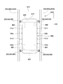
- FIG. 3 is an explanatory diagram showing an arrangement example of the upper laser sensor 121 and the lower laser sensor 122.
- FIG. 3 shows the vehicle 900 as viewed from above.
- the new transportation system 700 includes a track 800 and a vehicle 900.
- the track 800 includes a road surface 810, a guide rail 820, an upper left power line 840a, a lower left power line 840b, an upper right power line 840c, and a lower right power line 840d.
- the vehicle 900 includes a vehicle main body 910, a support 920, guide wheels 930, branch wheels 940, a current collector 950, and a traveling tire 960. As described with reference to FIG.
- the vehicle 900 further includes a first upper laser sensor 121a, a second upper laser sensor 121b, a third upper laser sensor 121c, a fourth upper laser sensor 121d, A lower laser sensor 122a, a second lower laser sensor 122b, a third lower laser sensor 122c, and a fourth lower laser sensor 122d are provided.
- the vehicle 900 travels on a travel route formed by the track 800.
- the vehicle 900 carries, for example, passengers or cargo.
- the vehicle main body 910 accommodates a conveyance target such as a passenger or cargo.
- a traveling tire 960 is provided at a lower portion of the vehicle main body 910.
- a support 920 is provided so as to protrude laterally from the vehicle main body 910.
- the vehicle body 910 includes a first upper laser sensor 121a, a second upper laser sensor 121b, a third upper laser sensor 121c, a fourth upper laser sensor 121d, and a first lower laser sensor 121a.
- a side laser sensor 122a, a second lower laser sensor 122b, a third lower laser sensor 122c, and a fourth lower laser sensor 122d are provided.
- the support 920 supports the guide wheel 930, the branch wheel 940, and the current collector 950. Specifically, guide wheels 930, branch wheels 940, and a current collector 950 are provided at the left and right ends of the support 920. The support 920 keeps the distance between the guide wheel 930, the branch wheel 940, the current collector 950, and the vehicle body 910 approximately constant.
- Guide wheel 930 restricts the orientation of vehicle 900 such that vehicle 900 travels on road surface 810 by hitting guide rail 820 when vehicle 900 travels.
- the branch wheel 940 moves along the branch rail 830 at a branch point of the track 800 to guide the vehicle 900 to one of the branch destination tracks 800.
- the current collector 950 contacts the power line 840 and receives power supply from the power line 840.
- the traveling tire 960 is provided below the vehicle main body 910 (on the side close to the road surface 810) and is in contact with the road surface 810. The vehicle 900 travels as the traveling tire 960 rotates. The vehicle 900 moves by this traveling.
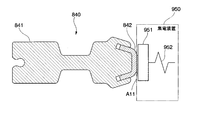
- FIG. 4 is an explanatory diagram illustrating an example of the positional relationship between the contact portion and the non-contact portion of the power line 840.
- FIG. 4 shows a schematic shape of each part in the cross section of the power line 840.
- the power line 840 includes a power line main body 841 and a contact member 842.
- the current collector 950 includes a rubbing plate 951 and a spring 952.
- the power line main body 841 is made of aluminum and has high conductivity and is relatively soft. If the entire power line 840 is made of aluminum, the power line 840 is extremely worn and needs to be replaced immediately. Therefore, a contact member 842 is provided at a portion where the power line 840 contacts the rubbing plate 951.
- the contact member 842 is made of stainless steel and is harder and less likely to wear than the aluminum power line body 841.
- the power line main body 841 corresponds to an example of a non-contact portion.
- a portion of the contact member 842 that contacts the rubbing plate 951 corresponds to an example of a contact portion.
- the region A11 corresponds to an example of a contact portion.
- the rubbing plate 951 contacts the power line 840 and receives power from the power line 840.
- the rubbing plate 951 is made of, for example, a carbon-based conductive material.
- the spring 952 presses the rubbing plate 951 against the power line 840.
- FIG. 5 is an explanatory diagram illustrating an example of the vertical direction of the upper laser sensor 121 and the lower laser sensor 122.
- FIG. 5 shows a state seen from the rear side of the vehicle 900 in the traveling direction of the vehicle 900.
- the first upper laser sensor 121a and the third upper laser sensor. 121c a first lower laser sensor 122a and a third lower laser sensor 122c are shown.
- the first upper laser sensor 121a is installed obliquely above the upper left power line 840a toward the upper left power line 840a.
- the first upper laser sensor 121a irradiates the upper left power line 840a with a laser and measures the distance between the first upper laser sensor 121a itself and the upper left power line 840a.
- the first lower laser sensor 122a is installed obliquely below the upper left power line 840a toward the upper left power line 840a.
- the first lower laser sensor 122a irradiates the upper left power line 840a with a laser and measures the distance between the first lower laser sensor 122a itself and the upper left power line 840a.
- the third upper laser sensor 121c is installed diagonally above the upper right power line 840c toward the upper right power line 840c.
- the third upper laser sensor 121c irradiates the upper right power line 840c with a laser and measures the distance between the third upper laser sensor 121c itself and the upper right power line 840c.
- the third lower laser sensor 122c is installed obliquely below the upper right power line 840c toward the upper right power line 840c. Accordingly, the third lower laser sensor 122c irradiates the upper right power line 840c with a laser and measures the distance between the third lower laser sensor 122c itself and the upper right power line 840c.
- the second upper laser sensor 121b is installed diagonally above the lower left power line 840b toward the lower left power line 840b.
- the second upper laser sensor 121b irradiates the lower left power line 840b with a laser and measures the distance between the second upper laser sensor 121b itself and the lower left power line 840b.
- the second lower laser sensor 122b is installed obliquely below the lower left power line 840b toward the lower left power line 840b. Accordingly, the second lower laser sensor 122b irradiates the lower left power line 840b with a laser and measures the distance between the second lower laser sensor 122b itself and the lower left power line 840b.
- the fourth upper laser sensor 121d is installed diagonally above the lower right power line 840d toward the lower right power line 840d. As a result, the fourth upper laser sensor 121d irradiates the lower right power line 840d with a laser and measures the distance between the fourth upper laser sensor 121d itself and the lower right power line 840d.
- the fourth lower laser sensor 122d is installed obliquely below the lower right power line 840d toward the lower right power line 840d. As a result, the fourth lower laser sensor 122d irradiates the lower right power line 840d with a laser and measures the distance between the fourth lower laser sensor 122d itself and the lower right power line 840d.
- the first upper laser sensor 121 a and the first lower laser sensor 122 a are installed at positions shifted in the longitudinal direction of the vehicle 900. Accordingly, the first upper laser sensor 121a and the first lower laser sensor 122a are installed at positions shifted in the traveling direction of the vehicle 900. Thereby, it can be avoided that the laser term output from the first upper laser sensor 121a interferes with the laser output from the first lower laser sensor 122a and the distance measurement accuracy is lowered.
- Combination of second upper laser sensor 121b and second lower laser sensor 122b, combination of third upper laser sensor 121c and third lower laser sensor 122c, fourth upper laser sensor 121d and fourth lower laser sensor 122d Is also the same as the combination of the first upper laser sensor 121a and the first lower laser sensor 122a.
- FIG. 6 is an explanatory diagram showing an example of a laser irradiation range by the upper laser sensor 121 and the lower laser sensor 122.
- the upper laser sensor 121 is positioned obliquely above the power line 840 and irradiates the laser toward the power line 840.
- the lower laser sensor 122 is positioned obliquely below the power line 840 and irradiates the laser toward the power line 840.
- the upper laser sensor 121 changes the direction of the laser up and down within the range of the angle A21. Thereby, upper laser sensor 121 scans at least a part of the worn part of power line 840 and a part of the non-wear part, and measures the distance between upper laser sensor 121 itself and the scanned part.
- a worn portion of the power line 840 is indicated by a region A11.
- the portion of the power line main body 841 in the power line 840 corresponds to an example of a non-wear portion.
- a line L11 indicates the center of the range in which the upper laser sensor 121 changes the direction of the laser.
- the center of the range in which the upper laser sensor 121 changes the laser direction is the center of the angle A21.
- the lower laser sensor 122 changes the direction of the laser up and down within the range of the angle A22. Accordingly, the lower laser sensor 122 scans at least a part of the worn part of the power line 840 and a part of the non-wear part, and measures the distance between the lower laser sensor 122 itself and the scanned part.
- a line L12 indicates the center of the range in which the lower laser sensor 122 changes the direction of the laser. In FIG. 6, the center of the range in which the lower laser sensor 122 changes the direction of the laser is the center of the angle A22.
- the upper laser sensor 121 and the lower laser sensor 122 scan the power line 840, respectively.
- the power line measurement unit 110 may include only one of the upper laser sensor 121 and the lower laser sensor 122. Thereby, the structure of the power line measurement part 110 can be simplified. Alternatively, the power line measurement unit 110 may include three or more laser sensors.
- the wear degree information acquisition device 10 may manage data for each laser sensor, Data of a plurality of racer sensors may be combined into one.
- the figure which shows the shape of the power line 840 described later with reference to FIG. 10 may be combined into a single figure by the wear degree information acquisition unit 291 for a plurality of laser sensors.
- the wear degree information acquisition unit 291 synthesizes data at different timings by the time converted from the difference in installation position in the traveling direction of the vehicle 900 into time.
- the position estimation laser sensor 130 measures the distance between the position estimation laser sensor 130 and surrounding objects for position estimation of the vehicle 900. Specifically, the position estimation laser sensor 130 repeats the distance measurement while changing the direction of the irradiated laser in the horizontal direction.
- the horizontal direction here is left and right.
- FIG. 7 is a graph showing an example of the distance measured by the position estimation laser sensor 130.
- the horizontal axis of the graph in FIG. 7 indicates time, and the vertical axis indicates the direction of the laser emitted by the position estimation laser sensor 130. The lower the vertical axis, the closer the laser direction is to the front of the vehicle 900, and the higher the vertical axis, the closer the laser direction to the rear of the vehicle 900.
- the front of the vehicle 900 is the traveling direction of the vehicle 900.
- the rear side of the vehicle 900 is on the opposite side of the traveling direction of the vehicle 900.
- the distance between the position estimation laser sensor 130 and the object irradiated with the laser is shown in gray scale. Lines L21, L22, and L23 are all darker than the other parts, indicating that the laser has hit an object relatively close to the position estimation laser sensor 130.
- the position estimation laser sensor 130 measures the distance from the front side of the vehicle 900 to the rear side of the vehicle 900 while changing the direction of the laser by a predetermined angle at a constant angular velocity in a direction transverse to the traveling direction of the vehicle 900. .
- the horizontal direction here is the horizontal direction.
- the position estimation laser sensor 130 returns the direction of the laser to the original direction without measuring the distance.
- the original direction here is the direction at the start of distance measurement.
- the position estimation laser sensor 130 again changes the laser direction by a predetermined angle from the front side of the vehicle 900 to the rear side of the vehicle 900 at a predetermined angular velocity. Measure.
- the position estimation laser sensor 130 repeats the distance measurement while changing the direction of the laser from the front side of the vehicle 900 to the rear side of the vehicle 900.
- the position estimation laser sensor 130 oscillates the laser at a sufficiently high speed relative to the traveling speed of the vehicle 900, the distance between the position estimation laser sensor 130 and the same object is repeatedly measured. Shaking the laser here means changing the direction of the laser. As a result, a line appears in the graph indicating the distance measured by the position estimation laser sensor 130 as in the example of FIG. In particular, in the portions of the line L21, the line L22, and the line L23, all are black lines because the laser hits an object relatively close to the position estimation laser sensor 130.
- the position estimation laser sensor 130 irradiates the laser at a height at which the laser hits the insulator 850 in FIG. At the timing when the laser hits the insulator 850, the distance between the position estimation laser sensor 130 and the object hit by the laser is closer than at other timings. Since a plurality of the insulators 850 are installed on the side of the track 800, a plurality of dark lines such as the line L21, the line L22, and the line L23 are generated.
- the height at which the position estimation laser sensor 130 irradiates the laser is not limited to the height at which the laser beam hits the insulator 850, but may be any height that has a different distance from the position estimation laser sensor 130 at the position at which the laser hits. .
- the same object is irradiated with the laser at the timing when the laser direction becomes the same in each scan. Therefore, as shown in the graph of FIG. 7, when time is taken on the horizontal axis and the laser direction is taken on the vertical axis, a line parallel to the horizontal axis appears.
- the relative position of the laser irradiation object with respect to the position estimation laser sensor 130 moves to the rear side of the vehicle 900 as time passes.
- the laser irradiation object here is an object to which the laser hits.
- the rear side of the vehicle 900 here is the opposite side to the traveling direction of the vehicle 900. For this reason, the line is inclined as in the example of FIG. The higher the speed of the vehicle 900, the greater the slope of the line.
- the relative speed of the laser irradiation object with respect to the position estimation laser sensor 130 can be obtained.
- this relative speed indicates the speed of the vehicle 900.
- the laser is irradiated at the same timing in the frontmost direction of the vehicle 900 and in the rearmost direction of the vehicle 900.
- the distance measured by the position estimation laser sensor 130 is acquired.
- An example of laser irradiation in the most forward direction of the vehicle 900 is indicated by a point P11.
- An example of laser irradiation in the most rearward direction of the vehicle 900 is indicated by a point P12.
- FIG. 8 is an explanatory diagram showing an example of the positional relationship between the position estimation laser sensor 130 and the laser irradiation object.
- a point P21 in FIG. 8 indicates the position of the position estimation laser sensor 130.
- a point P22 indicates the direction of the laser irradiation target when the laser is irradiated on the laser irradiation target in the most forward direction of the vehicle 900.
- an example of laser irradiation in the most forward direction of the vehicle 900 is indicated by the point P11.
- a point P23 indicates the direction of the laser irradiation target when the laser is irradiated on the laser irradiation target in the most rearward direction of the vehicle 900.
- an example of laser irradiation in the most rearward direction of the vehicle 900 is indicated by the point P12.
- Arrow B11 indicates the traveling direction of the vehicle 900.
- the position estimation laser sensor 130 measures both the distance D11 between the point P21 and the point P22 and the distance D12 between the point P21 and the point P23.
- the angle A31 at which the position estimation laser sensor 130 changes the direction of the laser is known.
- the distance D13 between the point P22 and the point P23 can be obtained from the distance D11, the distance D12, and the angle A31. By dividing this distance D13 by the time T11 (see FIG. 7) from when the irradiation object is positioned at the point P22 to when it is positioned at the point P23, the position of the irradiation object with respect to the position estimation laser sensor 130 is obtained. .
- this relative speed indicates the speed of the vehicle 900.
- the position estimation unit 292 obtains the traveling speed of the vehicle 900 in this way, and obtains the position of the vehicle 900 in kilometers by integrating the obtained traveling speed.
- the position estimation unit 292 obtains the speed of the vehicle 900 based on the distance measurement result by the position estimation laser sensor 130, so that the wiring of the vehicle 900 does not need to be connected to an existing device of the vehicle 900.
- the speed can be determined.
- the wear degree information acquisition device 10 is installed later in an existing vehicle 900, it is not necessary for the wear degree information acquisition device 10 to perform wiring for acquiring speed information from an existing device. In this respect, the installation work of the wear degree information acquisition device 10 is simplified. In particular, when the wear degree information acquisition device 10 is installed, it is possible to reduce the trouble of grasping the existing wiring of the vehicle 900, and to reduce the possibility that a problem occurs due to a wiring mistake.
- the timing detection unit 140 outputs a sampling timing signal every time the vehicle 900 travels at a constant interval.
- the timing detection unit 140 detects a sampling timing based on, for example, rotation of a motor coupling hub of a traveling motor of the vehicle 900.
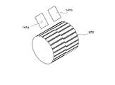
- FIG. 9 is an explanatory diagram showing an example of a method for detecting the rotation of the motor coupling hub.
- linear marks are attached to the outer periphery of the motor coupling hub 970 at regular intervals.
- the timing detection unit 140 includes a fiber sensor 141a and detects a mark, thereby detecting that the motor coupling hub 970 has rotated a certain angle. Thereby, the timing detection unit 140 detects that the vehicle 900 has traveled at a constant interval and outputs a sampling timing signal.
- the wear degree information acquisition unit 291 determines the wear degree of the power line 840 based on the distance measurement result. As described above, the wear level information acquisition unit 291 acquires information indicating the wear level of the power line 840 every time the timing detection unit 140 outputs the sampling timing signal. Thereby, the wear degree information acquisition unit 291 can determine the degree of wear of the power line 840 at the same interval in the traveling direction of the vehicle 900 without depending on the speed of the vehicle 900.
- the fiber sensor 141b is provided to detect the rotation direction of the motor coupling hub 970.
- the motor coupling hub 970 is further marked with a phase different from the mark detected by the fiber sensor 141a, and the fiber sensor 141b detects this mark.
- the phase different from the mark detected by the fiber sensor 141a shifting the phase by 90 degrees can be mentioned.
- the timing detection unit 140 detects the time from when the fiber sensor 141a detects the mark until the fiber sensor 141b detects the mark, and until the fiber sensor 141a detects the mark after the fiber sensor 141b detects the mark.
- the rotation direction of the motor coupling hub 970 can be detected.
- the timing detection unit 140 may not include the fiber sensor 141b.
- the sampling timing signal may be output at a timing other than every time the vehicle 900 travels at regular intervals, for example, the timing detection unit 140 outputs a sampling timing signal at regular intervals.
- the timing detector 140 may include a timer and count the lapse of the regular time. In this respect, the configuration of the timing detection unit 140 can be simplified.
- the wear degree information acquisition unit 291 may set the sampling period according to the speed of the vehicle 900. For example, the wear degree information acquisition unit 291 may acquire the speed of the vehicle 900 calculated by the position estimation unit 292, and set the sampling period according to the acquired speed. The wear degree information acquisition unit 291 sets the sampling period to be shorter as the speed of the vehicle 900 is higher. Thus, when the wear degree information acquisition unit 291 sets the sampling period according to the speed of the vehicle 900, the timing detection unit 140 is not necessary. That is, it is not necessary for the wear degree information acquisition device 10 to include the timing detection unit 140, and the configuration of the wear degree information acquisition device 10 can be simplified in this respect.
- the wear degree information acquisition apparatus main body 200 determines the degree of wear of the power line 840 based on the distance measured by the power line measurement unit 110 with the upper laser sensor 121 and the lower laser sensor 122.
- the wear degree information acquisition apparatus main body 200 is configured using, for example, a computer.
- the communication unit 210 communicates with the power line measurement unit 110, the position estimation laser sensor 130, and the timing detection unit 140.
- the communication unit 210 acquires a distance measurement value from the power line measurement unit 110 and the position estimation laser sensor 130.
- the communication unit 210 acquires a sampling timing signal output from the timing detection unit 140.
- the communication unit 210 is configured using, for example, a communication circuit included in the wear degree information acquisition apparatus main body 200.
- the display unit 230 includes a display screen such as a liquid crystal panel or an LED (Light Emitting Diode) panel, and displays various images. In particular, the display unit 230 displays the determination result of the degree of wear of the power line 840 by the wear degree information acquisition unit 291.
- the operation input unit 220 includes an input device such as a touch sensor provided on the display screen of the display unit 230 and constituting a touch panel, and receives a user operation.
- the storage unit 280 stores various information.
- storage part 280 is comprised using the memory
- the control unit 290 controls each unit of the wear degree information acquisition device 10 and executes various processes.
- the control unit 290 is configured by, for example, a CPU (Central Processing Unit) provided in the wear degree information acquisition apparatus main body 200 reading and executing a program from the storage unit 280.
- a CPU Central Processing Unit
- the wear degree information acquisition unit 291 is information indicating the degree of wear of the power line 840 based on the difference between the distance from the predetermined position of the vehicle 900 to the worn portion of the power line 840 and the distance from the predetermined position of the vehicle 900 to the non-wear portion. get.
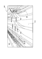
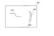
- FIG. 10 is an explanatory diagram illustrating an example of a display screen showing a positional relationship between a worn portion and a non-wear portion.
- information obtained by the upper laser sensor 121 scanning the power line 840 will be described as an example.
- the degree of wear of the power line 840 can be determined from information obtained by the lower laser sensor 122 scanning the power line 840.
- a line 10 indicates a shape obtained by the upper laser sensor 121 scanning the non-wear portion of the power line 840.
- a line L321 indicates a shape obtained by the upper laser sensor 121 scanning the worn portion in a state where the power line 840 is not worn.
- a line L322 indicates the shape obtained when the upper laser sensor 121 scans the worn portion when the power line 840 is worn.
- the storage unit 280 stores in advance the shape of the non-wear portion and the wear portion in a state where the power line 840 is not worn like the lines L311 and L321, including the positional relationship between the non-wear portion and the wear portion. deep.
- the wear degree information acquisition unit 291 associates the direction in which the upper laser sensor 121 irradiates the laser with the distance detected by the upper laser sensor 121.
- the obtained information is converted into information indicating the shape.
- the wear degree information acquisition unit 291 acquires information indicating the shape including the non-wear portion and the wear portion as in the example of the line L311 and the line L322.
- the wear degree information acquisition unit 291 reads information indicating the non-wear portion and the shape of the wear portion and the positional relationship between the non-wear portion and the wear portion when the power line 840 is not worn from the storage unit 280, and reads the upper laser sensor.
- the shape of the power line 840 obtained by the scanning of 121 is overlapped with the shape in a state where the power line 840 stored in the storage unit 280 is not worn.
- the wear degree information acquisition unit 291 is configured such that the shape of the power line 840 obtained by scanning the upper laser sensor 121 and the power line 840 stored in the storage unit 280 are worn as in the example of FIG. Overlap the non-wearing part with the shape in the absence.
- the degree of wear of the power line 840 is known.
- a portion between the line L321 and the line L322 corresponds to a portion where the power line 840 is worn.
- the information indicating the shape of the power line 840 illustrated in FIG. 10 corresponds to an example of information indicating the degree of wear of the power line 840.
- the wear degree information acquisition unit 291 superimposes the shape of the power line 840 obtained by scanning the upper laser sensor 121 as described above and the shape of the power line 840 in a state where the power line 840 is not worn on the non-wear portion. In the state, the distance between the worn parts is calculated. For example, one or more sampling points are determined in advance for the shape of the worn portion in a state where the power line 840 exemplified by the line L321 is not worn. Then, the wear degree information acquisition unit 291 obtains the distance between the wear point in the shape of the power line 840 obtained by scanning the upper laser sensor 121 and the sampling point for each sampling point. Then, the wear degree information acquisition unit 291 calculates the average of the obtained distances.
- the wear degree information acquisition unit 291 compares the obtained average value with a predetermined threshold value, and when the obtained average value is larger than the threshold value, displays a message prompting maintenance of the power line 840 together with information indicating the corresponding position. Display on the unit 230.
- the wear degree information acquisition unit 291 detects a place where the distance between the worn portion in a state where the power line 840 is not worn and the worn portion in the shape of the power line 840 obtained by the scanning of the upper laser sensor 121 is the largest. It may be.
- the wear degree information acquisition unit 291 has a predetermined threshold value and a distance between a wear portion in a state where the power line 840 is not worn at the detected location and a wear portion in the shape of the power line 840 obtained by scanning of the upper laser sensor 121. And compare. When the obtained distance is larger than the threshold value, a message that prompts maintenance of the power line 840 is displayed on the display unit 230 together with information indicating the corresponding position.
- the difference between the distance from the predetermined position of the vehicle 900 to the worn portion of the power line 840 and the distance from the predetermined position of the vehicle 900 to the non-wear portion used by the wear degree information acquisition unit 291 to acquire information indicating the degree of wear of the power line 840 Is not limited to the difference between these distances.
- the wear degree information acquisition unit 291 indicates the distance between the non-wear portion and the wear portion in the shape of the power line 840 obtained by scanning with the lower laser sensor 122, and the non-wear portion when the power line 840 is not worn. You may make it calculate the ratio which multiplied by the distance with a wear part. Then, when the calculated ratio is smaller than a predetermined threshold, the wear degree information acquisition unit 291 may cause the display unit 230 to display a message that prompts maintenance of the power line 840 together with information indicating the corresponding position.
- the user may determine the degree of wear of the power line 840.
- the display unit 230 displays the shape of the power line 840 obtained by scanning the upper laser sensor 121 and the shape in a state where the power line 840 is not worn in an overlapping manner. Then, the user may determine whether or not the maintenance of the power line 840 is necessary based on the obtained display, and may input the determination result to the wear degree information acquisition apparatus 10 using the operation input unit 220.
- the display unit 230 displays the shape of the power line 840 obtained by scanning the upper laser sensor 121 and the shape in a state where the power line 840 is not worn in an overlapping manner as in the example of FIG.
- the degree of wear of the power line 840 can be visually grasped.
- the display unit 230 may display only information indicating the position where the wear degree information acquisition unit 291 detects the wear of the power line 840.
- the position estimation unit 292 estimates the position of the vehicle 900. Specifically, as described with reference to FIG. 7, the position estimation unit 292 calculates the position of the vehicle 900 in kilometers based on the distance measurement result by the position estimation laser sensor 130.
- the wear degree information acquisition unit 291 detects the wear of the power line 840
- the information indicating the detection result and the kilometer calculated by the position estimation unit 292 are associated with each other and displayed on the display unit 230, and the storage unit 280 Remember. Thereby, the user of the wear degree information acquisition apparatus 10 can grasp the position where the maintenance of the power line 840 is necessary.
- the method by which the position estimation unit 292 acquires the position information of the vehicle 900 is not limited to the method using the distance measurement result by the position estimation laser sensor 130.
- the method by which the position estimation unit 292 acquires the vehicle 900 information may be any method that can acquire information that can identify the wear location when the wear degree information acquisition unit 291 detects the wear of the power line 840.
- the position estimation unit 292 may acquire the position information from the vehicle 900. It may be.
- the power line measurement unit 110 may scan the worn portion of the power line 840 obliquely with respect to the traveling direction of the vehicle 900. This point will be described with reference to FIGS.
- FIG. 11 is an explanatory diagram illustrating an example in which the power line measurement unit 110 scans a worn portion of the power line 840 approximately perpendicular to the traveling direction of the vehicle 900.
- FIG. 11 shows an example when the upper laser sensor 121 is viewed from the side of the upper laser sensor 121.
- FIG. 11 shows an example when the upper laser sensor 121 is viewed from a direction perpendicular to the traveling direction of the vehicle 900.
- a line L41 in FIG. 11 indicates the rotation center at which the upper laser sensor 121 changes the direction of the laser
- a line L42 indicates an example of the locus of the laser.
- the traveling direction of the vehicle 900 is indicated by an arrow B21.
- the upper laser sensor 121 changes the direction of the laser in a direction perpendicular to the rotation center.
- the center of rotation is set in the traveling direction of the vehicle 900, and the upper laser sensor 121 changes the direction of the laser to be perpendicular to the traveling direction of the vehicle 900.
- the rotation center is indicated by a line L41.
- upper laser sensor 121 scans the worn portion of power line 840 at a right angle to the traveling direction of vehicle 900.
- FIG. 12 is an explanatory diagram illustrating an example in which the power line measurement unit 110 scans a worn portion of the power line 840 obliquely with respect to the traveling direction of the vehicle 900.
- FIG. 12 shows an example when the upper laser sensor 121 is viewed from the side of the upper laser sensor 121.
- FIG. 12 shows an example when the upper laser sensor 121 is viewed from a direction perpendicular to the traveling direction of the vehicle 900.
- a line L51 in FIG. 12 indicates the rotation center at which the upper laser sensor 121 changes the direction of the laser, and a line L52 indicates an example of the locus of the laser.
- the traveling direction of the vehicle 900 is indicated by an arrow B21 as in the case of FIG.
- the center of rotation is set obliquely with respect to the traveling direction of the vehicle 900, and the upper laser sensor 121 causes the laser direction to be oblique with respect to the traveling direction of the vehicle 900.
- the center of rotation is indicated by a line L51.
- upper laser sensor 121 scans the worn portion of power line 840 obliquely with respect to the traveling direction of vehicle 900.
- the upper laser sensor 121 measures the distance from the position of the upper laser sensor 121 itself to each scanned position.
- the wear degree information acquisition unit 291 acquires information indicating the wear degree at each position scanned by the power line measurement unit 110 in the wear part of the power line 840.
- the wear degree information acquisition unit 291 can detect local wear occurring vertically in the wear portion of the power line 840. Specifically, the wear degree information acquisition unit 291 scans obliquely with respect to local wear occurring vertically in the wear portion of the power line 840. This increases the possibility that the wear portion and the scanning line intersect at least at one place, compared to the case where the wear degree information acquisition unit 291 scans in parallel with the direction of the wear portion.
- the case of the upper laser sensor 121 has been described as an example, but the same applies to the lower laser sensor 122.
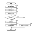
- FIG. 13 is a flowchart illustrating an example of a processing procedure in which the wear degree information acquisition apparatus 10 determines the wear degree of the power line.
- the wear degree information acquisition apparatus 10 performs the process of FIG. 13 every time the timing detection unit 140 detects the sampling timing.
- the power line measurement unit 110 scans the power line with a laser and measures the distance from the position of the power line measurement unit 110 to the position irradiated with the laser (step S101). Examples of the position of the power line measurement unit 110 include the position of the upper laser sensor 121 or the position of the lower laser sensor 122.
- the position estimation unit 292 estimates the position of the vehicle 900 (step S102). For example, as described with reference to FIGS. 7 and 8, the position estimation unit 292 calculates the position of the vehicle 900 in kilometers based on the distance measurement result by the position estimation laser sensor 130. Further, the wear degree information acquisition unit 291 determines the wear degree of the power line 840 based on the distance measured by the power line measurement unit 110 (step S103). For example, the wear degree information acquisition unit 291 calculates the distance between the wear part in the shape of the power line 840 and the wear part in the shape of the power line 840 obtained by scanning the power line measurement unit 110 when the power line 840 is not worn. To do. Then, the wear degree information acquisition unit 291 compares the calculated distance with a predetermined threshold value.
- the wear degree information acquisition unit 291 determines whether or not maintenance is necessary according to the determination result of the wear degree in step S103 (step S104). Specifically, when it is determined that the distance calculated in step S103 is greater than the threshold, the wear degree information acquisition unit 291 determines that maintenance is necessary. On the other hand, when it is determined that the distance calculated in step S103 is equal to or less than the threshold value, the wear degree information acquisition unit 291 determines that maintenance is unnecessary.
- the wear degree information acquisition unit 291 causes the display unit 230 to display the determination result.
- the wear degree information acquisition unit 291 causes the display unit 230 to display a message prompting maintenance, information indicating a position determined to require maintenance, and the shape of the power line 840 as in the example of FIG. 10 (step S111). ).
- the position information obtained in step S102 is used as information indicating the position determined as requiring maintenance.
- the wear degree information acquisition unit 291 causes the storage unit 280 to store a detection result indicating that wear has been detected (step S112).
- the wear degree information acquisition unit 291 includes information obtained by combining a detection result indicating that wear is detected, information indicating the position where wear is detected, and information indicating the shape of the power line 840 as in the example of FIG.
- the data is stored in the storage unit 280.
- the position information obtained in step S102 is used as information indicating the position where wear has been detected.
- step S104 when it is determined in step S104 that maintenance is not required (step S104: NO), the wear degree information acquisition unit 291 stores a detection result indicating that no wear is detected in the storage unit 280 (step S121). .
- the wear degree information acquisition unit 291 combines a detection result indicating that wear is not detected, information indicating a position where wear is detected, and information indicating the shape of the power line 840 as in the example of FIG. Information is stored in the storage unit 280.
- the position information obtained in step S102 is used as information indicating the position where wear has been detected.
- the wear degree information acquisition apparatus main body 200 may be installed in an office, and information obtained by running the vehicle 900 may be acquired afterwards to determine the degree of wear of the electric wire.
- the position estimation function of the vehicle 900 by the position estimation unit 292 may be performed by a computer provided on the ground side such as a vehicle base.
- the wear degree acquisition device 10 may transmit the acquired data to a ground computer, and the computer may estimate the position of the vehicle 900 based on the received data.
- a display device provided on the ground side such as a vehicle base may perform all or a part of various images such as a wear degree and a message displayed by the display unit 230.
- the wear degree acquisition device 10 or a computer that has received data from the wear degree acquisition device 10 transmits data such as a wear degree determination result and a message to the display device on the ground side, and the display device is based on the received data. Then, an image such as a wear degree determination result and a message may be displayed.
- the power line measurement unit 110 includes the distance from the predetermined position of the vehicle 900 for each of the wear part that contacts the vehicle 900 and the non-wear part that does not contact the vehicle 900 in the power line 840 that supplies power to the vehicle 900. Measure.
- Examples of the predetermined position of the vehicle 900 include the position of the upper laser sensor 121 or the position of the lower laser sensor 122.
- the wear degree information acquisition unit 291 acquires information indicating the wear degree of the power line 840 based on the difference between the distance from the predetermined position of the vehicle 900 to the worn portion and the distance from the predetermined position of the vehicle 900 to the non-wear portion. To do.
- the wear degree information acquisition device 10 can detect the wear of the power line 840 even when the width of the wear portion is kept substantially constant even if the power line 840 is worn.
- the power line 840 shown in FIG. 4 keeps the width of the worn portion substantially constant even if the worn portion is worn.
- the worn portion is a portion where the power line 840 comes into contact with the rubbing plate 951 as indicated by a region A11.
- the wear degree information acquisition device 10 can detect the wear of the power line 840 as described above. If vehicle 900 travels once on track 800, the degree of wear of power line 840 can be determined for all sections traveled by track 800. Conventionally, the maintenance inspector enters the track and determines the wear level of the power line by visual inspection or the like. However, according to the wear degree information acquisition device 10, the burden on the maintenance inspector can be reduced.
- the timing detection unit 140 outputs a sampling timing signal every time the vehicle 900 travels at a constant interval.
- the wear level information acquisition unit 291 acquires information indicating the wear level of the power line 840 every time the timing detection unit 140 outputs a sampling timing signal.
- the wear degree information acquisition unit 291 can determine the degree of wear of the power line 840 at the same interval in the traveling direction of the vehicle 900 without depending on the speed of the vehicle 900. Therefore, even when the vehicle 900 is traveling at a high speed, it can be avoided that the sampling interval becomes too wide and the determination accuracy of the degree of wear of the power line 840 is lowered. Further, even when the vehicle 900 is traveling at a low speed, it is possible to avoid an enormous amount of data due to an increase in the number of samplings per length of the power line 840.
- the power line measurement unit 110 scans the worn portion obliquely with respect to the traveling direction of the vehicle 900 and measures the distance from the predetermined position of the vehicle 900 to each scanned position.
- Examples of the predetermined position of the vehicle 900 include the position of the upper laser sensor 121 or the position of the lower laser sensor 122.
- the wear degree information acquisition part 291 acquires the information which shows the wear degree in each position which the power line measurement part 110 scanned among the wear parts. Accordingly, it is possible to increase the possibility that the wear degree information acquisition unit 291 can detect local wear occurring vertically in the wear portion of the power line 840.
- a program for realizing all or part of the functions of the control unit 290 is recorded on a computer-readable recording medium, and the program recorded on the recording medium is read into a computer system and executed. You may perform the process of.
- the “computer system” includes an OS and hardware such as peripheral devices.
- the “computer-readable recording medium” refers to a storage device such as a flexible medium, a magneto-optical disk, a portable medium such as a ROM or a CD-ROM, and a hard disk incorporated in a computer system.
- the program may be a program for realizing a part of the functions described above, and may be a program capable of realizing the functions described above in combination with a program already recorded in a computer system.
- An embodiment of the present invention is a power line measurement unit that measures a distance from a predetermined position of the vehicle for each of a wear part that contacts the vehicle and a non-wear part that does not contact the vehicle, among power lines that supply power to the vehicle. And a wear degree information acquisition unit that acquires information indicating the degree of wear of the power line based on a difference between a distance from the predetermined position of the vehicle to the wear portion and a distance from the predetermined position of the vehicle to the non-wear portion. And a wear degree information acquisition device. According to this embodiment, even when the power line is worn, the wear of the power line can be detected even when the width of the worn portion is kept substantially constant.
- Wear degree information acquisition apparatus 110 Power line measurement part 121 Upper side laser sensor 122 Lower side laser sensor 130 Position estimation laser sensor 140 Timing detection part 200 Wear degree information acquisition apparatus main body 210 Communication part 220 Operation input part 230 Display part 280 Storage part 290 Control unit 291 Wear degree information acquisition unit 292 Position estimation unit 900 Vehicle
Landscapes
- Engineering & Computer Science (AREA)
- Physics & Mathematics (AREA)
- General Physics & Mathematics (AREA)
- Manufacturing & Machinery (AREA)
- Mechanical Engineering (AREA)
- Electromagnetism (AREA)
- Radar, Positioning & Navigation (AREA)
- Remote Sensing (AREA)
- Length Measuring Devices By Optical Means (AREA)
- Length Measuring Devices With Unspecified Measuring Means (AREA)
- Image Processing (AREA)
- Image Analysis (AREA)
Abstract
La présente invention concerne un dispositif d'acquisition d'informations de degré d'usure qui est pourvu de : une unité de mesure de câble d'alimentation qui mesure une distance d'un emplacement prescrit dans un véhicule à une partie d'usure, en contact avec le véhicule, d'un câble d'alimentation qui fournit de l'énergie électrique au véhicule, et une distance de l'emplacement prescrit dans le véhicule à une partie non-usure, n'étant pas en contact avec le véhicule, du câble d'alimentation ; et une unité d'acquisition d'informations de degré d'usure qui acquiert des informations indiquant le degré d'usure du câble d'alimentation, sur la base de la différence entre la distance de l'emplacement prescrit dans le véhicule à la partie d'usure, et la distance de l'emplacement prescrit dans le véhicule à la partie non-usure.
Priority Applications (2)
| Application Number | Priority Date | Filing Date | Title |
|---|---|---|---|
| US16/078,027 US10864825B2 (en) | 2016-02-22 | 2017-02-08 | Wear degree information acquiring device, wear degree information acquiring method, vehicle and program |
| SG11201807037SA SG11201807037SA (en) | 2016-02-22 | 2017-02-08 | Wear degree information acquiring device, wear degree information acquiring method, vehicle, and program |
Applications Claiming Priority (2)
| Application Number | Priority Date | Filing Date | Title |
|---|---|---|---|
| JP2016031397A JP6632130B2 (ja) | 2016-02-22 | 2016-02-22 | 摩耗度合い情報取得装置、摩耗度合い情報取得方法、車両及びプログラム |
| JP2016-031397 | 2016-02-22 |
Publications (1)
| Publication Number | Publication Date |
|---|---|
| WO2017145754A1 true WO2017145754A1 (fr) | 2017-08-31 |
Family
ID=59685030
Family Applications (1)
| Application Number | Title | Priority Date | Filing Date |
|---|---|---|---|
| PCT/JP2017/004526 Ceased WO2017145754A1 (fr) | 2016-02-22 | 2017-02-08 | Dispositif d'acquisition d'informations de degré d'usure, procédé d'acquisition d'informations de degré d'usure, véhicule, et programme |
Country Status (4)
| Country | Link |
|---|---|
| US (1) | US10864825B2 (fr) |
| JP (1) | JP6632130B2 (fr) |
| SG (1) | SG11201807037SA (fr) |
| WO (1) | WO2017145754A1 (fr) |
Families Citing this family (2)
| Publication number | Priority date | Publication date | Assignee | Title |
|---|---|---|---|---|
| JP6825548B2 (ja) * | 2017-12-22 | 2021-02-03 | Jfeスチール株式会社 | トロリー線の異常診断方法、トロリー線の異常診断装置及び電動移動体 |
| JP7462386B2 (ja) * | 2019-06-14 | 2024-04-05 | 株式会社シマノ | 検出装置、検出方法、生成方法、コンピュータプログラムおよび記憶媒体 |
Citations (6)
| Publication number | Priority date | Publication date | Assignee | Title |
|---|---|---|---|---|
| JPH05278503A (ja) * | 1992-04-02 | 1993-10-26 | Hitachi Electron Eng Co Ltd | トロリー線の高さ測定装置 |
| JP2003011702A (ja) * | 2001-06-29 | 2003-01-15 | Mitsubishi Heavy Ind Ltd | 摩耗計測方法及び摩耗計測装置 |
| JP2006258531A (ja) * | 2005-03-16 | 2006-09-28 | Act Denshi Kk | レール断面測定方法及びそれに使用されるレール断面測定装置 |
| EP1855084A2 (fr) * | 2006-05-11 | 2007-11-14 | Siemens Aktiengesellschaft | Procédé pour déterminer la hauteur restante d'une caténaire et dispositifs destinés à la réalisation du procédé |
| JP2015068675A (ja) * | 2013-09-27 | 2015-04-13 | 株式会社日立ハイテクファインシステムズ | トロリ線測定装置及びトロリ線測定方法 |
| JP2015184174A (ja) * | 2014-03-25 | 2015-10-22 | 公益財団法人鉄道総合技術研究所 | トロリ線の摩耗量算定方法およびトロリ線の摩耗量算定装置 |
Family Cites Families (3)
| Publication number | Priority date | Publication date | Assignee | Title |
|---|---|---|---|---|
| JP4635657B2 (ja) | 2005-03-11 | 2011-02-23 | 株式会社明電舎 | 画像処理によるトロリ線摩耗測定装置 |
| JP2007271446A (ja) * | 2006-03-31 | 2007-10-18 | Meidensha Corp | 画像処理によるトロリ線摩耗測定装置 |
| JP4973108B2 (ja) * | 2006-10-05 | 2012-07-11 | 株式会社明電舎 | トロリ線の摩耗測定装置 |
-
2016
- 2016-02-22 JP JP2016031397A patent/JP6632130B2/ja active Active
-
2017
- 2017-02-08 SG SG11201807037SA patent/SG11201807037SA/en unknown
- 2017-02-08 US US16/078,027 patent/US10864825B2/en active Active
- 2017-02-08 WO PCT/JP2017/004526 patent/WO2017145754A1/fr not_active Ceased
Patent Citations (6)
| Publication number | Priority date | Publication date | Assignee | Title |
|---|---|---|---|---|
| JPH05278503A (ja) * | 1992-04-02 | 1993-10-26 | Hitachi Electron Eng Co Ltd | トロリー線の高さ測定装置 |
| JP2003011702A (ja) * | 2001-06-29 | 2003-01-15 | Mitsubishi Heavy Ind Ltd | 摩耗計測方法及び摩耗計測装置 |
| JP2006258531A (ja) * | 2005-03-16 | 2006-09-28 | Act Denshi Kk | レール断面測定方法及びそれに使用されるレール断面測定装置 |
| EP1855084A2 (fr) * | 2006-05-11 | 2007-11-14 | Siemens Aktiengesellschaft | Procédé pour déterminer la hauteur restante d'une caténaire et dispositifs destinés à la réalisation du procédé |
| JP2015068675A (ja) * | 2013-09-27 | 2015-04-13 | 株式会社日立ハイテクファインシステムズ | トロリ線測定装置及びトロリ線測定方法 |
| JP2015184174A (ja) * | 2014-03-25 | 2015-10-22 | 公益財団法人鉄道総合技術研究所 | トロリ線の摩耗量算定方法およびトロリ線の摩耗量算定装置 |
Also Published As
| Publication number | Publication date |
|---|---|
| US20190047440A1 (en) | 2019-02-14 |
| US10864825B2 (en) | 2020-12-15 |
| SG11201807037SA (en) | 2018-09-27 |
| JP6632130B2 (ja) | 2020-01-15 |
| JP2017150850A (ja) | 2017-08-31 |
Similar Documents
| Publication | Publication Date | Title |
|---|---|---|
| JP7247206B2 (ja) | 鉄道車両および軌道区間を検測する方法 | |
| CN103465938B (zh) | 轨道交通车辆的快速精确定位装置及定位方法 | |
| US6995556B2 (en) | Electromagnetic gage sensing system and method for railroad track inspection | |
| CN100494882C (zh) | 基于图像处理的架空线磨损测量装置 | |
| EP3717330B1 (fr) | Système et procédé d'inspection d'un rail | |
| US11359911B2 (en) | Abrasion inspection apparatus, abrasion inspection method, and program | |
| WO2021123463A1 (fr) | Procédé de capture et de traitement in situ et en temps réel de paramètres géométriques de lignes ferroviaires | |
| KR101446057B1 (ko) | 침목 균열 검사 장비 | |
| JP7202506B2 (ja) | 軌道状態監視装置、軌道状態監視システム及び軌道状態監視方法 | |
| CN107074255A (zh) | 用于确定用于有轨车辆的轨道的至少一个特征的设备和方法以及有轨车辆 | |
| CN106794852B (zh) | 用于检测有轨车辆的车辆环境的设备和方法以及有轨车辆 | |
| TWI641515B (zh) | Insulator detection device and obstacle detection method | |
| JP2012173254A (ja) | 検測方法及び装置 | |
| JP6632130B2 (ja) | 摩耗度合い情報取得装置、摩耗度合い情報取得方法、車両及びプログラム | |
| KR101086023B1 (ko) | 자기부상선로의 궤도 검측방법 | |
| JP2019045449A (ja) | サードレール測定装置及び方法 | |
| CN108248636A (zh) | 基于激光源定位的三角坑图像检测方法 | |
| JP2020172230A (ja) | 位置検知方法及び位置検知システム | |
| JP2014110737A (ja) | すり板の局部摩耗検出装置とその局部摩耗検出プログラム | |
| KR20150054363A (ko) | 전차선 편위 정보를 이용한 고정밀 열차 위치 검지 시스템 | |
| RU2652673C1 (ru) | Способ определения стрелочных переводов и положения остряков | |
| JP2000038059A (ja) | トロリ線の摩耗測定装置 | |
| JP6389783B2 (ja) | 渡り線相対位置管理装置及び方法 | |
| JP2000350305A (ja) | パンタグラフ摺り板摩耗計測装置 | |
| CN211765583U (zh) | 一种列车轮对三维表面高精度测量系统 |
Legal Events
| Date | Code | Title | Description |
|---|---|---|---|
| NENP | Non-entry into the national phase |
Ref country code: DE |
|
| WWE | Wipo information: entry into national phase |
Ref document number: 11201807037S Country of ref document: SG |
|
| 121 | Ep: the epo has been informed by wipo that ep was designated in this application |
Ref document number: 17756195 Country of ref document: EP Kind code of ref document: A1 |
|
| 122 | Ep: pct application non-entry in european phase |
Ref document number: 17756195 Country of ref document: EP Kind code of ref document: A1 |