WO2017145844A1 - Joint homocinétique du type à coulissement - Google Patents
Joint homocinétique du type à coulissement Download PDFInfo
- Publication number
- WO2017145844A1 WO2017145844A1 PCT/JP2017/005184 JP2017005184W WO2017145844A1 WO 2017145844 A1 WO2017145844 A1 WO 2017145844A1 JP 2017005184 W JP2017005184 W JP 2017005184W WO 2017145844 A1 WO2017145844 A1 WO 2017145844A1
- Authority
- WO
- WIPO (PCT)
- Prior art keywords
- constant velocity
- velocity universal
- universal joint
- type constant
- ball
- Prior art date
- Legal status (The legal status is an assumption and is not a legal conclusion. Google has not performed a legal analysis and makes no representation as to the accuracy of the status listed.)
- Ceased
Links
Images














Classifications
-
- F—MECHANICAL ENGINEERING; LIGHTING; HEATING; WEAPONS; BLASTING
- F16—ENGINEERING ELEMENTS AND UNITS; GENERAL MEASURES FOR PRODUCING AND MAINTAINING EFFECTIVE FUNCTIONING OF MACHINES OR INSTALLATIONS; THERMAL INSULATION IN GENERAL
- F16D—COUPLINGS FOR TRANSMITTING ROTATION; CLUTCHES; BRAKES
- F16D3/00—Yielding couplings, i.e. with means permitting movement between the connected parts during the drive
- F16D3/02—Yielding couplings, i.e. with means permitting movement between the connected parts during the drive adapted to specific functions
- F16D3/06—Yielding couplings, i.e. with means permitting movement between the connected parts during the drive adapted to specific functions specially adapted to allow axial displacement
-
- F—MECHANICAL ENGINEERING; LIGHTING; HEATING; WEAPONS; BLASTING
- F16—ENGINEERING ELEMENTS AND UNITS; GENERAL MEASURES FOR PRODUCING AND MAINTAINING EFFECTIVE FUNCTIONING OF MACHINES OR INSTALLATIONS; THERMAL INSULATION IN GENERAL
- F16D—COUPLINGS FOR TRANSMITTING ROTATION; CLUTCHES; BRAKES
- F16D3/00—Yielding couplings, i.e. with means permitting movement between the connected parts during the drive
- F16D3/16—Universal joints in which flexibility is produced by means of pivots or sliding or rolling connecting parts
- F16D3/20—Universal joints in which flexibility is produced by means of pivots or sliding or rolling connecting parts one coupling part entering a sleeve of the other coupling part and connected thereto by sliding or rolling members
-
- F—MECHANICAL ENGINEERING; LIGHTING; HEATING; WEAPONS; BLASTING
- F16—ENGINEERING ELEMENTS AND UNITS; GENERAL MEASURES FOR PRODUCING AND MAINTAINING EFFECTIVE FUNCTIONING OF MACHINES OR INSTALLATIONS; THERMAL INSULATION IN GENERAL
- F16D—COUPLINGS FOR TRANSMITTING ROTATION; CLUTCHES; BRAKES
- F16D3/00—Yielding couplings, i.e. with means permitting movement between the connected parts during the drive
- F16D3/16—Universal joints in which flexibility is produced by means of pivots or sliding or rolling connecting parts
- F16D3/20—Universal joints in which flexibility is produced by means of pivots or sliding or rolling connecting parts one coupling part entering a sleeve of the other coupling part and connected thereto by sliding or rolling members
- F16D3/22—Universal joints in which flexibility is produced by means of pivots or sliding or rolling connecting parts one coupling part entering a sleeve of the other coupling part and connected thereto by sliding or rolling members the rolling members being balls, rollers, or the like, guided in grooves or sockets in both coupling parts
- F16D3/223—Universal joints in which flexibility is produced by means of pivots or sliding or rolling connecting parts one coupling part entering a sleeve of the other coupling part and connected thereto by sliding or rolling members the rolling members being balls, rollers, or the like, guided in grooves or sockets in both coupling parts the rolling members being guided in grooves in both coupling parts
- F16D3/224—Universal joints in which flexibility is produced by means of pivots or sliding or rolling connecting parts one coupling part entering a sleeve of the other coupling part and connected thereto by sliding or rolling members the rolling members being balls, rollers, or the like, guided in grooves or sockets in both coupling parts the rolling members being guided in grooves in both coupling parts the groove centre-lines in each coupling part lying on a sphere
- F16D3/2245—Universal joints in which flexibility is produced by means of pivots or sliding or rolling connecting parts one coupling part entering a sleeve of the other coupling part and connected thereto by sliding or rolling members the rolling members being balls, rollers, or the like, guided in grooves or sockets in both coupling parts the rolling members being guided in grooves in both coupling parts the groove centre-lines in each coupling part lying on a sphere where the groove centres are offset from the joint centre
-
- F—MECHANICAL ENGINEERING; LIGHTING; HEATING; WEAPONS; BLASTING
- F16—ENGINEERING ELEMENTS AND UNITS; GENERAL MEASURES FOR PRODUCING AND MAINTAINING EFFECTIVE FUNCTIONING OF MACHINES OR INSTALLATIONS; THERMAL INSULATION IN GENERAL
- F16D—COUPLINGS FOR TRANSMITTING ROTATION; CLUTCHES; BRAKES
- F16D3/00—Yielding couplings, i.e. with means permitting movement between the connected parts during the drive
- F16D3/16—Universal joints in which flexibility is produced by means of pivots or sliding or rolling connecting parts
- F16D3/20—Universal joints in which flexibility is produced by means of pivots or sliding or rolling connecting parts one coupling part entering a sleeve of the other coupling part and connected thereto by sliding or rolling members
- F16D3/22—Universal joints in which flexibility is produced by means of pivots or sliding or rolling connecting parts one coupling part entering a sleeve of the other coupling part and connected thereto by sliding or rolling members the rolling members being balls, rollers, or the like, guided in grooves or sockets in both coupling parts
- F16D3/223—Universal joints in which flexibility is produced by means of pivots or sliding or rolling connecting parts one coupling part entering a sleeve of the other coupling part and connected thereto by sliding or rolling members the rolling members being balls, rollers, or the like, guided in grooves or sockets in both coupling parts the rolling members being guided in grooves in both coupling parts
- F16D3/226—Universal joints in which flexibility is produced by means of pivots or sliding or rolling connecting parts one coupling part entering a sleeve of the other coupling part and connected thereto by sliding or rolling members the rolling members being balls, rollers, or the like, guided in grooves or sockets in both coupling parts the rolling members being guided in grooves in both coupling parts the groove centre-lines in each coupling part lying on a cylinder co-axial with the respective coupling part
- F16D3/227—Universal joints in which flexibility is produced by means of pivots or sliding or rolling connecting parts one coupling part entering a sleeve of the other coupling part and connected thereto by sliding or rolling members the rolling members being balls, rollers, or the like, guided in grooves or sockets in both coupling parts the rolling members being guided in grooves in both coupling parts the groove centre-lines in each coupling part lying on a cylinder co-axial with the respective coupling part the joints being telescopic
Definitions
- the present invention relates to a sliding type constant velocity universal joint used for automobiles and various industrial machines.
- the drive shaft for automobiles usually uses a fixed type constant velocity universal joint on the drive wheel side (also called outboard side), and a sliding type constant velocity universal joint on the differential side (also called inboard side). These two constant velocity universal joints are connected by an intermediate shaft.
- the fixed type constant velocity universal joint can take a large operating angle but does not slide in the axial direction.
- the sliding type constant velocity universal joint is slidable in the axial direction, but cannot take a large operating angle.
- the maximum allowable angle of the fixed constant velocity universal joint used on the drive wheel side is set to 46 ° to 50 ° so that it can also correspond to the angle at the time of full steering.
- the maximum allowable angle of the joint is set to 23 ° to 30 ° so that the movement of the suspension can be absorbed.
- the maximum operating angle is obtained in the full bound state where the suspension sinks most and the full rebound state where the suspension is fully extended.
- SUV vehicles sports, utility vehicles
- a normal angle a large drive shaft angle
- Patent Document 1 As a drive shaft for an automobile, a shaft that can slide in the axial direction by a ball spline using a fixed constant velocity universal joint has already been proposed (Patent Document 1, Non-Patent Document 1).
- Sliding constant velocity universal joints include double offset type constant velocity universal joints (DOJ) consisting of outer joint members, inner joint members, cages and 6 to 8 balls, outer joint members, trunnions, 3
- DOJ double offset type constant velocity universal joints
- TJ tripod type constant velocity universal joint
- Patent Document 1 proposes a drive shaft that uses two fixed constant velocity universal joints connected by a shaft having a ball spline.
- This drive shaft uses a fixed type constant velocity universal joint with a large operating angle on the differential side, but the ball spline provided on the shaft incurs a significant cost increase and the axial length of the ball spline. Therefore, the drive shaft is also limited in dimension. For this reason, the drive shaft of patent document 1 has remained for the application for some special vehicles.
- Non-Patent Document 1 describes a drive shaft having a structure in which ball splines are arranged on the outer periphery of a fixed type constant velocity universal joint. It was put into practical use for some luxury vehicles in the early 1960s, before the rise of front-wheel drive vehicles (FF vehicles). This was a structure before the practical use of DOJ as a standard for sliding constant velocity universal joints, and this structure was very expensive. As a result, it was deceived by currently used DOJ and TJ. As described above, Non-Patent Document 1 is a structure before DOJ as a sliding type constant velocity universal joint is put into practical use, and is not intended to increase the angle of the sliding type constant velocity universal joint.
- FF vehicles front-wheel drive vehicles
- the present invention can greatly increase the operating angle of a sliding type constant velocity universal joint and can obtain a stable sliding performance.
- An object of the present invention is to provide a sliding type constant velocity universal joint that can greatly contribute to diversifying automobile designs with an increased degree of freedom in layout of drive system components.
- the inventors of the present invention have made various studies to achieve the above-described object, and efficiently arrange a ball spline on the outer periphery of a compact fixed type constant velocity universal joint to reduce torque loss and reduce cost and weight.
- the sliding type constant velocity universal joint shown in FIGS. 17 to 19 was previously proposed.
- the sliding type constant velocity universal joint 101 includes an outer joint member 106 in which eight track grooves 111 are formed on the spherical inner peripheral surface 110, and an outer face 8 facing the track grooves 111 of the outer joint member 106 on the spherical outer peripheral surface 112.
- a Rzeppa-type fixed constant velocity universal joint portion 102 is constituted by a cage 109 that is disposed between the joint member 107 and holds the torque transmission ball 108, and the fixed type constant velocity universal joint portion 102 is connected to the outer cylinder member. 103, and a ball spline portion between the inner peripheral surface 124 of the outer cylindrical member 103 and the outer peripheral surface 125 of the outer joint member 106 of the fixed type constant velocity universal joint portion 102.
- the ball 128 of the ball spline portion 104 is held by a ball spline holder 129 disposed between the inner peripheral surface 124 of the outer cylinder member 103 and the outer peripheral surface 125 of the outer joint member 106. Is.
- the sliding type constant velocity universal joint 101 In the sliding type constant velocity universal joint 101, the operating angle is taken by the inner fixed type constant velocity universal joint portion 102, and the axial slide is taken by the ball spline portion 104. As described above, the function of taking the operating angle and the function of taking the slide in the axial direction are divided into the fixed type constant velocity universal joint portion 102 and the ball spline portion 104. Therefore, the sliding type constant velocity universal joint 101 does not cause the axial force problem due to the operating angle generated in the currently used sliding type constant velocity universal joint that simultaneously performs the function of taking the operating angle and the function of sliding. (Noise, Vibration, Harshness) characteristics are good, and the performance is also epoch-making.
- the sliding constant velocity universal joint 101 greatly increases the operating angle, so that the usable range of the drive shaft angle is expanded, the degree of freedom of layout of drive system parts is improved, and the automobile Can greatly contribute to design.
- the ball spline part 104 which has the holder
- the ball spline retainer 129 is externally moved during the relative movement in the axial direction between the outer cylinder member 103 and the fixed type constant velocity universal joint portion 102. It can move in the axial direction with respect to both the cylindrical member 103 and the fixed type constant velocity universal joint portion 102. For this reason, it has been found during the development process that the center position of the ball spline holder 129 at the time of sliding is changed, and that man-hours are required for phase alignment at the time of assembly of the ball spline portion 104.
- the relative movement amount between the outer cylinder member 103 and the fixed type constant velocity universal joint portion 102 is limited by the interference between the ball 128 and the retaining rings 130, 131, 132 (see FIG. 19), but the ball spline is retained. It has also been found that when the center position of the container 129 is biased, the ball 128 may drop from the ball spline grooves 126 and 127 during slide-in and slide-out. Focusing on this problem, the present inventors worked on improving the sliding constant velocity universal joint 101.
- the present invention includes an outer joint member in which a plurality of track grooves are formed on a spherical inner peripheral surface, and a plurality of tracks facing the track grooves of the outer joint member on a spherical outer peripheral surface.
- a fixed type constant velocity universal joint portion is formed from a cage that holds the torque transmission ball, and the fixed type constant velocity universal joint portion is fitted into an outer cylinder member, and an inner peripheral surface of the outer cylinder member and the fixed type
- the sliding type constant velocity universal joint in which a ball spline portion is formed between the outer peripheral surface of the outer joint member of the constant velocity universal joint portion, the ball of the ball spline portion is connected to the inner peripheral surface of the outer cylindrical member and the outer side.
- the axial movement amount of the ball spline holder is half of the relative axial movement amount of the outer cylinder member and the fixed type constant velocity universal joint portion. It is characterized by having a regulating mechanism for regulating.
- the operating angle of the sliding constant velocity universal joint is greatly expanded, so the usable range of the drive shaft angle is expanded, the degree of freedom in the layout of drive system parts is improved, and the automobile is diversified It is possible to realize a sliding type constant velocity universal joint that can greatly contribute to the design.
- a ball spline part having a cage can be arranged on the outer periphery of a compact fixed type constant velocity universal joint part to reduce a torque loss and realize a sliding type constant velocity universal joint with reduced cost and weight.
- the ball spline retainer is equipped with a centering mechanism that regulates the amount of axial movement of the outer cylinder member and the fixed constant velocity universal joint to half of the amount of relative movement in the axial direction. The center position of the spline retainer can be prevented from being biased, and the ball can be prevented from falling off the ball spline groove during slide-in and slide-out, so that stable sliding performance can be obtained.
- the above ball spline retainer can move both in the axial direction and in the circumferential direction when the balls in the ball spline part move in the axial direction, thereby reducing the number of steps for phase alignment during assembly of the ball spline part. Assembling workability is improved.
- the above alignment mechanism is fixed to the outer cylindrical member, the pocket portion having a long window shape in the circumferential direction, which accommodates at least a pair of long holes inclined in the circumferential direction provided in the ball spline retainer and the balls of the ball spline portion. It is desirable that each of the constant velocity universal joints is composed of an engagement element that engages with the elongated hole. Thereby, the alignment mechanism can be realized with a simple configuration.
- the ball spline groove of the ball spline part is arranged in a phase between adjacent track grooves of the outer joint member of the fixed type constant velocity universal joint part. Therefore, a ball spline part can be efficiently arrange
- the stem shaft portion is integrally formed with the outer cylinder member, the connection with the differential gear is easy.
- the fixed constant velocity universal joint is preferably composed of a Rzeppa constant velocity universal joint or a constant velocity universal joint having a cross track groove. Thereby, torque loss can be reduced and it can be set as the sliding type constant velocity universal joint which suppressed cost and weight.
- the sliding type constant velocity universal joint of the present invention since the operating angle is greatly expanded, the usable range of the angle of the drive shaft is expanded, the degree of freedom of layout of the drive system parts is improved, and various It is possible to realize a sliding type constant velocity universal joint that can greatly contribute to the design of automobiles.
- the ball spline retainer is equipped with a centering mechanism that regulates the amount of axial movement of the outer cylinder member and the fixed constant velocity universal joint to half of the amount of relative movement in the axial direction.
- the center position of the spline retainer can be prevented from being biased, and the ball can be prevented from falling off the ball spline groove during slide-in and slide-out, so that stable sliding performance can be obtained.
- a ball spline part having a cage can be arranged on the outer periphery of a compact fixed type constant velocity universal joint part to reduce a torque loss and realize a sliding type constant velocity universal joint with reduced cost and weight.
- the ball spline portion can be efficiently arranged in the phase between adjacent track grooves of the outer joint member, and the cost and weight can be further suppressed.
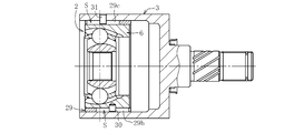
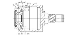
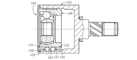
- FIG. 4 is a longitudinal sectional view taken along the line G1-NG2 in FIG. 3, showing the sliding type constant velocity universal joint according to the first embodiment of the present invention.
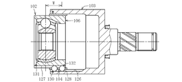
- FIG. 4 is a longitudinal sectional view taken along line G1-NG3 in FIG. 3, showing the sliding type constant velocity universal joint according to the first embodiment of the present invention.
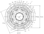
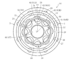
- FIG. 2 is a side view taken along the line HH in FIG. 1.
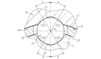
- FIG. 2 is an enlarged cross-sectional view of one ball and a track groove along the line PP in FIG. 1.
- FIG. 5B is a left side view of FIG. 5B, showing the ball spline holder alone of FIG. 1. It is a front view which shows the ball spline holder single-piece
- FIG. 1 It is a perspective view which shows the ball spline holder simple substance of FIG. It is a longitudinal cross-sectional view which shows the state which the sliding type constant velocity universal joint of FIG. 1 slid out and took the operating angle. It is the longitudinal cross-sectional view of the state which showed the state which the sliding type constant velocity universal joint of FIG. 1 slid from the center position, and slid in. It is the longitudinal cross-sectional view of the state of the center position which shows the state which the sliding type constant velocity universal joint of FIG. 1 slid from the center position. It is the longitudinal cross-sectional view of the state which showed the state which the sliding type constant velocity universal joint of FIG. 1 slid from the center position, and slid out.
- FIG. 13 is a longitudinal sectional view taken along line G1-NG2 in FIG. 12, showing a sliding type constant velocity universal joint according to a second embodiment of the present invention.
- FIG. 12 is a side view taken along the line HH in FIG. 11. It is a longitudinal cross-sectional view of the outer joint member of FIG. It is a figure which shows the outer peripheral surface of the inner side coupling member of FIG. It is sectional drawing of the outer joint member seen in the plane M containing the ball
- FIG. 15 is a cross-sectional view of the inner joint member viewed in a plane Q including the ball track center line of the track groove and the joint center in FIG. 14.
- FIG. 17 is a longitudinal sectional view taken along the line GN-G of FIG. 16, showing the previously proposed sliding type constant velocity universal joint.
- FIG. 18 is a side view taken along the line HH in FIG. 17. It is the longitudinal cross-sectional view of the state which showed the state which the sliding type constant velocity universal joint of FIG. 17 slid from the center position, and slid in. It is the longitudinal cross-sectional view of the state of the center position which shows the state which the sliding type constant velocity universal joint of FIG. 17 slid from the center position. It is the longitudinal cross-sectional view of the state which showed the state which the sliding type constant velocity universal joint of FIG. 17 slid from the center position, and slid out.
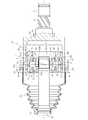
- FIG. 1 shows a sliding type constant velocity universal joint according to a first embodiment of the present invention, which is a longitudinal sectional view taken along line G1-N-G2 in FIG. 3, and FIG. FIG. 3 is a longitudinal sectional view taken along line G3, and FIG. 3 is a side view taken along line HH in FIG. 1 and 2, only the portions of the long holes 29b and 29c (see FIG. 8) of the ball spline retainer 29 are cross sections taken along the center lines T1-T1 and T2-T2 in the longitudinal direction of the long holes 29b and 29c. Indicates. The same applies to the following drawings.
- the sliding type constant velocity universal joint 1 includes a fixed type constant velocity universal joint portion 2, an outer cylindrical member 3, and an outer cylindrical member 3. And a ball spline portion 4 (see FIG. 2) formed between the fixed type constant velocity universal joint portion 2.
- the fixed type constant velocity universal joint portion 2 is constituted by a Rzeppa type constant velocity universal joint having eight torque transmission balls (hereinafter, also simply referred to as balls), and includes an outer joint member 6, an inner joint member 7, a ball 8 and The cage 9 is a main component.
- Eight curved track grooves 11 are formed on the spherical inner peripheral surface 10 of the outer joint member 6 at equal intervals in the circumferential direction and along the axial direction.
- Eight curved track grooves 13 facing the track grooves 11 of the outer joint member 6 are formed on the spherical outer peripheral surface 12 of the inner joint member 7 at equal intervals in the circumferential direction and along the axial direction. .
- Eight balls 8 for transmitting torque are incorporated one by one between the track groove 11 of the outer joint member 6 and the track groove 13 of the inner joint member 7.
- a cage 9 that holds the ball 8 is disposed between the spherical inner peripheral surface 10 of the outer joint member 6 and the spherical outer peripheral surface 12 of the inner joint member 7.
- the ball 8 is accommodated in the pocket portion 9 a of the cage 9.
- the spherical outer circumferential surface 14 of the cage 9 is fitted with the spherical inner circumferential surface 10 of the outer joint member 6, and the spherical inner circumferential surface 15 of the cage 9 is fitted with the spherical outer circumferential surface 12 of the inner joint member 7.
- the centers of curvature of the spherical inner peripheral surface 10 of the outer joint member 6 and the spherical outer peripheral surface 12 of the inner joint member 7 are formed at the joint center O, respectively.
- the center of curvature Oo of the curved track groove 11 of the outer joint member 6 and the center of curvature Oi of the curved track groove 13 of the inner joint member 7 are opposite to the center O of the joint in the axial direction.
- a female spline (spline includes serration; the same applies hereinafter) 17 is formed in the inner diameter hole 16 of the inner joint member 7, and the male spline 20 formed at the end of the intermediate shaft 19 is fitted to the female spline 17. , And are connected so that torque can be transmitted.
- the inner joint member 7 and the intermediate shaft 19 are positioned in the axial direction by a retaining ring 21.
- FIG. 4 is an enlarged cross-sectional view of one ball and a track groove along the line PP in FIG.
- the cross-sectional shape of the track grooves 11 and 13 is formed in an elliptical shape or a Gothic arch shape.
- the ball 8 is in angular contact with the track groove 11 of the outer joint member 6 at two points C12 and C13, and is in angular contact with the track groove 13 of the inner joint member 7 at two points C15 and C16.
- the angle (contact angle ⁇ ) between the straight line passing through the ball center O 2 and the contact points C12, C13, C15, C16 and the straight line passing through the ball center O 2 and the curvature centers Oo, Oi is 30 ° to It is preferable to set to about 45 °.
- the fixed type constant velocity universal joint portion 2 is fitted into the outer cylindrical member 3, and the inner peripheral surface 24 of the outer cylindrical member 3 and the outer joint member 6 of the fixed type constant velocity universal joint portion 2.
- the ball spline portion 4 is formed between the outer peripheral surface 25 and the outer peripheral surface 25.
- eight ball spline grooves 26 having a circular arc cross section are formed on the inner peripheral surface 24 of the outer cylinder member 3 in a straight line in the axial direction.
- eight ball spline grooves 27 having a circular arc cross section are formed linearly in the axial direction corresponding to the ball spline grooves 26 of the outer cylinder member 3.
- Two balls 28 are incorporated in each groove of each pair of ball spline grooves 26 and 27.
- a cage 29 for holding the ball 28 is disposed between the outer peripheral surface 25 of the outer joint member 6 and the inner peripheral surface 24 of the outer cylinder member 3.
- Two pocket portions 29 a of the cage 29 are provided for each ball spline groove 26, 27, that is, a pocket portion 29 a for each ball 28 is provided.
- Each ball 28 is accommodated and held in the pocket portion 29 a of the cage 29, and the cage 29 slides while holding the ball 28.
- the inner and outer peripheral surfaces of the cage 29 are respectively guided by the outer peripheral surface 25 of the outer joint member 6 and the inner peripheral surface 24 of the outer cylinder member 3.
- the fixed type constant velocity universal joint portion 2 slides with respect to the outer cylindrical member 3 as each ball 28 of the ball spline portion 4 rolls on the ball spline grooves 26 and 27.
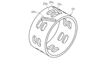
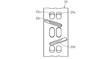
- FIGS. 5a to 5c show a single ball spline holder 29, FIG. 5a is a left side view of FIG. 5b, FIG. 5b is a front view, and FIG. 5c is a perspective view.
- the ball spline retainer 29 has a cylindrical shape, and as shown in FIGS. 5b and 5c, a pocket portion 29a for accommodating the ball 28 of the ball spline portion 4 (see FIG. 2) is formed in a long window shape in the circumferential direction. Yes.
- the pocket parts 29a are arranged in two rows in the axial direction at eight equal positions in the circumferential direction. As shown in FIG.
- one ball 28 is incorporated into each pocket part 29a, and one ball spline groove is formed.
- Two balls 28 are incorporated into 26 and 27.
- a pair of long holes 29b and 29c are provided between pocket portions 29a adjacent in the circumferential direction.
- the long holes 29b and 29c are inclined in the circumferential direction at equal inclination angles in opposite directions, and extend substantially along the axial direction.
- the inclination angle is preferably about 5 ° to 10 ° from the viewpoint of ensuring the guideability of the ball spline holder 29 and the sliding amount. As shown in FIG.
- a pin 30 as an engaging member provided in the outer joint member 6 of the fixed type constant velocity universal joint portion 2 is fitted into the elongated hole 29b, and the outer cylinder member 3 is inserted into the elongated hole 29c.
- the pin 31 as the provided engagement element is fitted and the alignment mechanism S of the ball spline holder 29 is configured. Details thereof will be described later.
- the ball spline retainer 29 is made of resin in consideration of weight reduction and low friction because it does not receive a large load.
- the ball spline retainer 29 is preferably a commonly used resin having excellent wear resistance, seizure resistance, and the like, and examples of the thermoplastic resin include polyethylene, polyamide, polyacetal, polyethylene terephthalate, polyethylene terephthalate, Examples include polycarbonate, polyphenylene sulfide, polyether sulfone, polyether imide, polyamide imide, polyether ether ketone, and thermoplastic polyimide.
- Thermosetting resins include thermosetting polyimide, epoxy resin, and phenol resin. These synthetic resins are mentioned.
- glass fibers or carbon fibers based on a thermoplastic resin such as polyamide, polyphenylene sulfide, or polyether ether ketone.
- the material of the ball spline cage 29 it is preferable to use a polyamide resin excellent in tensile elongation, tensile strength, impact resistance, wear resistance, lubricity and the like.
- the polyamide resin include PA66 (polyamide 66), PA46 (polyamide 46), PA9T (polyamide 9T), PA11 (polyamide 11), and PA6 (polyamide 6). Since it is excellent in tensile elongation, tensile strength, impact resistance, wear resistance, lubricity, etc., a high-quality ball spline retainer 29 can be obtained.
- thermosetting resin such as thermosetting polyimide, epoxy resin, or phenol resin
- the ball spline retainer 29 is made of resin, but is not limited thereto, and may be made of metal such as a steel pipe.
- the ball spline grooves 26 and 27 are arranged with two balls 28 per groove for reducing the number of parts.
- the number is not limited to this, and an appropriate number can be set as long as it is two or more.
- bowl 28 was illustrated in the holder
- a stem 3b connected to a differential gear (not shown) is integrally formed on the bottom 3a of the outer cylinder member 3.
- the stem portion 3b is formed with a spline 3c at the shaft end and a sliding bearing portion 3d having an oil groove at the center.
- the spline 3c is fitted into the spline hole of the differential gear and connected so as to be able to transmit torque. Since the stem shaft portion 3b is integrally formed with the outer cylinder member 3, the connection with the differential gear is easy.
- a bellows-like boot 22 is mounted on the outer peripheral surface of the outer cylinder member 3 and the outer peripheral surface of the intermediate shaft 19 connected to the inner joint member 7. Specifically, one end of the boot 22 is fastened and fixed to the outer peripheral surface of the outer cylinder member 3 by the boot band 32, and the other end of the boot 22 is fastened to the outer peripheral surface of the intermediate shaft 19 by the boot band 33. It is fixed. As a result, leakage of grease as a lubricant sealed inside the joint is prevented and entry of foreign matter from the outside is prevented.
- the ball spline groove 27 formed in the outer peripheral surface 25 of the outer joint member 6 is formed in the spherical inner peripheral surface 10 of the outer joint member 6. It is arranged in the surplus portion of the phase between the adjacent track grooves 11.
- the sliding type constant velocity universal joint 1 according to the present embodiment will be described later in detail with respect to a configuration in which the ball spline portion 4 is efficiently arranged on the outer periphery of the compact fixed type constant velocity universal joint portion 2 to reduce cost and weight.
- FIG. 6 shows a state in which the sliding type constant velocity universal joint 1 of the present embodiment is slid out.
- the fixed type constant velocity universal joint portion 2 slides to the opening side of the outer cylinder member 3 by rolling of the ball spline portion 4.
- the inner and outer peripheral surfaces of the ball spline retainer 29 are guided by the outer peripheral surface 25 of the outer joint member 6 and the inner peripheral surface 24 of the outer cylinder member 3, the posture of the ball spline retainer 29 is stabilized.
- the ball 28 accommodated in the pocket portion 29a of the ball spline holder 29 rolls smoothly on the ball spline grooves 26 and 27 (see FIG. 2) in the axial direction.
- the sliding type constant velocity universal joint 1 of the present embodiment the operating angle is taken by the inner fixed type constant velocity universal joint portion 2, and the axial slide is taken by the ball spline portion 4.
- the function of taking the operating angle and the function of taking the slide in the axial direction are divided into the fixed type constant velocity universal joint portion 2 and the ball spline portion 4. Therefore, the sliding type constant velocity universal joint 1 of the present embodiment has an axial force problem due to the operating angle generated in the currently used sliding type constant velocity universal joint that simultaneously performs the function of taking the operating angle and the function of sliding.
- the NVH Noise, Vibration, Harshness
- the fixed type constant velocity universal joint portion 2 In the slide-out state, the fixed type constant velocity universal joint portion 2 overhangs with respect to the outer cylinder member 3 to take an operating angle, and a bending moment is applied to the ball spline portion 4, but the ball spline groove 26, The load can be supported by two balls 28 arranged per one groove 27.
- the operating angle of the sliding type constant velocity universal joint 1 of the present embodiment is greatly expanded to about 40 ° to 45 °, so that the usable range of the angle of the drive shaft is expanded, and the layout of the drive system components is increased. The degree of freedom increases, and it can greatly contribute to the design of a diverse car.
- FIGS. 7 is a longitudinal sectional view showing a state in which the sliding type constant velocity universal joint is slid from the center position.
- FIG. 7a shows a state in which the slide-in is performed
- FIG. 7b shows a state in the center position
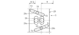
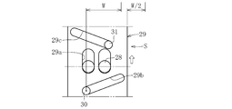
- FIG. 8 is a schematic diagram showing the alignment mechanism of the ball spline holder.
- FIG. 8a shows a slide-in state
- FIG. 8b shows a central position
- FIG. 8c shows a slide-out state.
- the alignment mechanism S of the ball spline retainer 29 is in the state shown in FIG. 8b.
- the pin 30 provided on the outer joint member 6 of the fixed type constant velocity universal joint portion 2 is located in the center of the long hole 29b of the ball spline retainer 29, and the length of the long hole 29c.
- the pin 31 provided in the outer cylinder member 3 is located in the center of the direction.
- bowl 28 is located in the circumferential direction center of the long window of the pocket part 29a.
- the alignment mechanism S of the ball spline holder 29 is in the state shown in FIG. 8a. Specifically, the pin 30 provided on the outer joint member 6 moves to the right end in the length direction of the long hole 29b of the ball spline retainer 29, and the outer cylinder member moves to the left end in the length direction of the long hole 29c. 3 is moved. At the same time, the ball spline retainer 29 rotates in the direction of the white arrow, and the ball 28 is positioned on the upper side in the circumferential direction of the long window of the pocket portion 29a.
- the ball spline retainer 29 rotates in the direction of the white arrow, and is half the axial relative movement amount (sliding amount) W of the outer joint member 6 and the outer cylindrical member 3. That is, it moves by W / 2. Thereby, the ball spline retainer 29 is positioned with no deviation with respect to the outer joint member 6 and the outer cylinder member 3.
- the pocket portion 29a is formed in a long window shape, and the circumferential direction is between the pocket portion 29a and the ball 28 even when the relative movement amount is W.
- the circumferential length of the pocket portion 29a is set so that some gaps remain.
- the relative movement amount W in the axial direction between the outer joint member 6 and the outer cylinder member 3 is determined by the axial length of the long holes 29b and 29c of the ball spline retainer 29. When the pins 30 and 31 come into contact with the end portions of the long holes 29b and 29c, further relative movement of the outer joint member 6 and the outer cylinder member 3 is prevented.
- the relative movement amount (slide amount) W is about 20 to 30 mm, although it varies depending on the joint size and the type of vehicle mounted.
- the alignment mechanism S of the ball spline holder 29 is in the state shown in FIG. 8c.
- the pin 30 provided on the outer joint member 6 moves to the left end in the length direction of the elongated hole 29b of the ball spline retainer 29, and the length of the elongated hole 29c is increased.
- the pin 31 provided on the outer cylinder member 3 moves to the right end in the direction, and the ball spline retainer 29 rotates in the direction of the white arrow, so that the ball 28 is positioned on the lower side in the circumferential direction of the long window of the pocket portion 29a. It becomes a state to do. Also in this case, as shown in FIG.
- the ball spline retainer 29 rotates in the direction of the white arrow, and is half of the relative movement amount W in the axial direction of the outer joint member 6 and the outer cylindrical member 3, that is, W
- the ball spline holder 29 is positioned with no deviation with respect to the outer joint member 6 and the outer cylinder member 3.
- the alignment mechanism S of the ball spline retainer 29 also has a retaining function.
- the ball spline retainer 29 can move both in the axial direction and in the circumferential direction when the ball 28 of the ball spline part 4 moves in the axial direction, thereby reducing the phase alignment man-hours when the ball spline part 4 is assembled. Can be reduced, and the assembly workability is improved.
- the ball spline part 4 is efficiently arranged on the outer periphery of the compact fixed type constant velocity universal joint part 2 to reduce torque loss and reduce the cost and weight.
- the structure of will be described.
- the length of each is PCR, and both are equal.
- the ball spline grooves 26 and 27 may be prematurely peeled or broken due to stress deformation of the ball spline grooves 26 and 27. It has been found.
- the sliding type constant velocity universal joint 1 of the present embodiment has an efficient arrangement of the fixed type constant velocity universal joint portion 2 and the ball spline portion 4 using the eight compact balls 8 described above. Together, it reduces torque loss, is lightweight and compact, and can reduce costs.
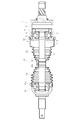
- FIG. 9 shows a front wheel drive shaft 40 of an automobile to which the sliding constant velocity universal joint 1 of the present embodiment is applied.
- a fixed type constant velocity universal joint 41 is connected to one end of the intermediate shaft 19, and the sliding type constant velocity universal joint 1 of the present embodiment is connected to the other end.
- the fixed type constant velocity universal joint 41 is a Rzeppa type constant velocity universal joint using eight balls, and has the same internal configuration as the fixed type constant velocity universal joint portion 2 of the sliding type constant velocity universal joint 1.
- the fixed type constant velocity universal joint 41 is connected to a hub wheel (not shown) on which driving wheels are mounted, and the sliding type constant velocity universal joint 1 is connected to a differential gear (not shown).
- the sliding type constant velocity universal joint 1 of the present embodiment Since the sliding type constant velocity universal joint 1 of the present embodiment is used, the operating angle is greatly expanded, the usable area of the angle of the drive shaft 40 is expanded, and the degree of freedom of layout of the drive system parts is improved. It can greatly contribute to the design of diversifying automobiles. Moreover, since the ball spline part 4 which has a holder
- the drive shaft 40 is highly efficient and light and compact, which leads to cost reduction.
- the alignment mechanism S is provided. The center position of the ball spline holder 29 at the time of sliding can be prevented from being biased, and the ball 28 can be prevented from falling off from the ball spline grooves 26 and 27 at the time of sliding in and sliding out, so that stable sliding performance can be obtained.
- FIG. 10a to 10c show modified examples of the ball spline holder 29.
- FIG. 10a is a left side view of the ball spline holder 29
- FIG. 10b is a front view
- FIG. 10c is a perspective view.
- This modification is different from the ball spline holder 29 of the first embodiment in that two pairs of long holes 29b and 29c are provided.
- the number of pins 30 and 31 is two, respectively, and the operation of the alignment mechanism S of the ball spline holder 29 is more stable. Since other configurations are the same as those of the first embodiment, all the contents described in the first embodiment are applied mutatis mutandis, and description thereof is omitted.
- the sliding type constant velocity universal joint 51 of this embodiment is different from the first embodiment in the fixed type constant velocity universal joint portion 52. Since other configurations are the same as those in the first embodiment, portions having the same functions are denoted by the same reference numerals and description thereof is omitted.
- the fixed type constant velocity universal joint portion 52 mainly includes an outer joint member 56, an inner joint member 57, a ball 58, and a cage 59.
- each of the eight track grooves 61 and 63 of the outer joint member 56 and the inner joint member 57 is inclined in the circumferential direction with respect to the axis NN of the joint, and the inclined direction is the circumferential direction.
- the track grooves 61A, 61B and 63A, 63B adjacent to each other are formed in opposite directions.
- eight balls 58 are arranged at the intersections of the track grooves 61A, 63A and 61B, 63B that form pairs of the outer joint member 56 and the inner joint member 57.
- the fixed type constant velocity universal joint portion 52 is formed of a constant velocity universal joint having the tolerance track grooves 61 and 63. Details of the track grooves 61 and 63 will be described later.
- the ball spline groove 27 formed on the outer peripheral surface 75 of the outer joint member 56 has a spherical inner periphery of the outer joint member 56. Arranged in the surplus portion of the phase between adjacent track grooves 61 formed in the surface 60. Also in the sliding type constant velocity universal joint 51 of the present embodiment, the ball spline portion 4 is efficiently arranged on the outer periphery of the compact and highly efficient fixed type constant velocity universal joint portion 52 to reduce cost and weight. As shown in FIG. 11 and FIG. 12, the alignment mechanism S of the ball spline holder 29 is also provided in this embodiment.
- the aligning mechanism S includes a pair of elongated holes 29b and 29c provided in the ball spline holder 29 and inclined in the circumferential direction, pins 30 and 31 as engaging elements, and a ball spline holder. It is comprised from the long window-shaped pocket part 29a which permits the rotation of 29 circumferential directions.
- Figure 11 shows the longitudinal section of the joint.
- the term “ball trajectory centerline” will be used to describe the shape and shape of the track groove extending substantially in the axial direction, such as an inclined state and a curved state.
- the ball trajectory center line means a locus drawn by the center of the ball when the ball arranged in the track groove moves along the track groove. Therefore, the inclination state of the track groove is the same as the inclination state of the ball track center line, and the arc shape or the straight state of the track groove is the arc shape or straight state of the ball track center line. The same.
- the track groove 61 of the outer joint member 56 has a ball trajectory center line X
- the track groove 61 has a first arc-shaped ball trajectory center line Xa with the joint center O as the center of curvature.
- Track groove portion 61a and a second track groove portion 61b having a linear ball track center line Xb.
- the ball track center line Xa of the second track groove portion 61b extends to the ball track center line Xa of the first track groove portion 61a.
- Xb is smoothly connected as a tangent.
- the track groove 63 of the inner joint member 57 has a ball track center line Y
- the track groove 63 includes a first track groove portion 63a having an arc-shaped ball track center line Ya with the joint center O as the center of curvature.
- a second track groove portion 63b having a straight ball track center line Yb, and the ball track center line Yb of the second track groove portion 63b is smoothly tangent to the ball track center line Ya of the first track groove portion 63a. It is connected to the.
- the track groove depth can be made uniform. And processing can be facilitated.
- the cross-sectional shape of the track grooves 61 and 63 is formed in an elliptical shape or a Gothic arch shape as in FIG. 3 described above, and the track grooves 61 and 63 and the ball 58 have a contact angle (about 30 ° to 45 °). So-called angular contact. Therefore, the ball 58 is in contact with the side surfaces of the track grooves 61 and 63 that are slightly apart from the groove bottoms of the track grooves 61 and 63.
- FIG. 13 shows a partial longitudinal section of the outer joint member 56.
- the track grooves 61 of the outer joint member 56 are denoted by the reference numerals of the track grooves 61A and 61B because of the difference in inclination direction.
- the plane M including the ball track center line X and the joint center O of the track groove 61A is inclined by an angle ⁇ with respect to the joint axis NN.
- the track groove 61B adjacent to the track groove 61A in the circumferential direction is not shown in the figure, but the plane M including the ball track center line X and the joint center O of the track groove 61B is connected to the joint axis NN.
- the track groove 61A is inclined by an angle ⁇ in a direction opposite to the inclination direction of the track groove 61A.
- the entire area of the ball track center line X of the track groove 61A that is, both the ball track center line Xa of the first track groove portion 61a and the ball track center line Xb of the second track groove portion 61b are on the plane M. Is formed.
- the present invention is not limited to this, and a mode in which only the ball trajectory center line Xa of the first track groove 61a is included in the plane M can also be implemented. Therefore, at least the first track groove portion 61a of the first track groove portion 61a including the ball trajectory center line Xa and the plane M including the joint center O is inclined with respect to the joint axis NN and the inclination direction is adjacent in the circumferential direction. What is necessary is just to be formed in the mutually opposite direction by 61a.
- the track groove codes are supplemented.
- reference numeral 61 is given, and the first track groove part is given reference numeral 61a, and the second track groove part is given reference numeral 61b.
- reference numerals 61A and 61B are assigned, reference numerals 61Aa and 61Ba are assigned to the first track groove parts, and reference signs 61Ab and 61Bb are assigned to the second track groove parts.
- the track grooves of the inner joint member 57 to be described later are also given the same reference numerals.
- FIG. 14 shows the outer peripheral surface of the inner joint member 57.
- the track grooves 63 of the inner joint member 57 are given the reference numerals of the track grooves 63A and 63B because of the difference in the inclination direction.
- the plane Q including the ball track center line Y and the joint center O of the track groove 63A is inclined by an angle ⁇ with respect to the joint axis NN.
- the plane Q including the ball track center line Y and the joint center O of the track groove 63B is in relation to the joint axis NN.
- the track groove 63A is inclined by an angle ⁇ in a direction opposite to the inclination direction of the track groove 63A.
- the inclination angle ⁇ is set to 4 ° to 12 ° in consideration of the operability of the fixed type constant velocity universal joint portion 52 and the spherical surface width F (see FIG. 12) on the closest side of the track groove of the inner joint member 57. Is preferred.
- the entire area of the ball track center line Y of the track groove 63A that is, the ball track center line Ya of the first track groove portion 63a and the second track.
- Both the ball trajectory center lines Yb of the grooves 63b are formed on the plane Q.
- the present invention is not limited to this, and a mode in which only the ball trajectory center line Ya of the first track groove 63a is included in the plane Q can also be implemented.
- a plane Q including at least the ball track center line Ya of the first track groove 63a and the joint center O is inclined in the circumferential direction with respect to the joint axis NN, and the inclined direction is adjacent to the circumferential direction in the first direction.
- the track grooves 63a may be formed in opposite directions.
- the ball trajectory center line Y of the track groove 63 of the inner joint member 57 is based on the plane P including the joint center O in the state where the operating angle is 0 °, and the ball trajectory center line of the track groove 61 paired with the outer joint member 56 X and mirror image symmetry.
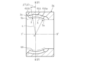
- FIG. 15 shows the track groove 61A of the outer joint member 56.
- the track groove 61B is the same as the track groove 61A except for the inclination direction opposite to the track groove 61A. Since there is, explanation is omitted.
- a track groove 61A is formed in the spherical inner peripheral surface 60 of the outer joint member 56 along the axial direction.
- the track groove 61A has a ball track center line X
- the track groove 61A has a first track groove portion 61Aa having an arc-shaped ball track center line Xa with the joint center O as the center of curvature (no axial offset).
- a second track groove 61Ab having a linear ball trajectory center line Xb. Then, at the end A on the opening side of the ball track center line Xa of the first track groove portion 61Aa, the linear ball track center line Xb of the second track groove portion 61Ab is smoothly connected as a tangent line. That is, the end A is a connection point between the first track groove 61Aa and the second track groove 61Ab.
- the ball trajectory center line Xb is formed so as to approach the joint axis NN (see FIG. 11) toward the opening side.
- L be a straight line connecting the end A and the joint center O.
- the joint axis N′-N ′ projected onto the plane M (see FIG. 13) including the ball track center line X and the joint center O of the track groove 61A is inclined by ⁇ with respect to the joint axis NN.
- ⁇ ′ be the angle formed by the perpendicular line K and the straight line L at the joint center O of N′ ⁇ N ′.
- FIG. 16 is a cross-sectional view of the track groove 63A of FIG. 14 described above as seen from the plane Q including the ball trajectory center line Y and the joint center O. Accordingly, similarly to FIG. 15, strictly, it is not a longitudinal sectional view in a plane including the joint axis NN, but shows a section inclined by an angle ⁇ .
- FIG. 16 shows the track groove 63A of the inner joint member 57, but the track groove 63B is the same as the track groove 63A except for the inclination direction opposite to the track groove 63A. Since there is, explanation is omitted.
- a track groove 63A is formed in the spherical outer peripheral surface 62 of the inner joint member 57 substantially along the axial direction.
- the track groove 63A has a ball track center line Y
- the track groove 63A has a first track groove portion 63Aa having an arc-shaped ball track center line Ya with the joint center O as the center of curvature (no axial offset).
- a second track groove 63Ab having a linear ball trajectory center line Yb.
- the ball track center line Yb of the second track groove portion 63Ab is smoothly connected as a tangent at the end B on the back side of the ball track center line Ya of the first track groove portion 63Aa.
- the end B is a connection point between the first track groove 63Aa and the second track groove 63Ab. Since the end portion B is located on the back side from the joint center O, the linear shape of the second track groove portion 63Ab connected as a tangent at the end portion B on the back side of the ball track center line Ya of the first track groove portion 63Aa.
- the ball trajectory center line Yb is formed so as to approach the joint axis NN (see FIG. 11) toward the back side. Thereby, it is possible to secure the effective track length at the maximum operating angle and to suppress the wedge angle from becoming excessive.
- R be the straight line connecting the end B and the joint center O.
- the joint axis N′-N ′ projected onto the plane Q (see FIG. 14) including the ball trajectory center line Y and the joint center O of the track groove 63A is inclined by ⁇ with respect to the joint axis NN.
- ⁇ ′ be the angle formed by the perpendicular line K and the straight line R at the joint center O of N′ ⁇ N ′.
- the angle ⁇ formed with respect to the plane P including the joint center O in the state where the straight lines L and R are at an operating angle of 0 ° will be described.
- the ball 58 moves by ⁇ / 2 with respect to the plane P including the joint center O of the outer joint member 56 and the inner joint member 57.
- the angle ⁇ is determined from 1 ⁇ 2 of the frequently used operating angle, and the range of the track groove with which the ball 58 contacts is determined within the frequently used operating angle range.
- the operating angle that is frequently used is defined.
- the common angle of the joint refers to the operating angle generated in the fixed constant velocity universal joint of the front drive shaft when the vehicle is traveling straight on a horizontal and flat road surface when the vehicle is in a straight traveling state.
- the service angle is usually selected and determined between 2 ° and 15 ° according to the design conditions for each vehicle type.
- the frequently used operating angle is not the high operating angle that occurs when the above-mentioned automobile is turned right or left at an intersection, for example, but the operating angle that occurs in a fixed constant velocity universal joint on a curved road that runs continuously This is also determined according to the design conditions for each vehicle type.
- the operating angle that is frequently used is targeted at a maximum of 20 °.
- the angle ⁇ formed by the straight lines L and R with respect to the plane P including the joint center O in a state where the operating angle is 0 ° is set to 3 ° to 10 °.
- the angle ⁇ is not limited to 3 ° to 10 °, and can be appropriately set according to the design conditions of the vehicle type. By setting the angle ⁇ to 3 ° to 10 °, it can be used for various types of vehicles.
- the end A of the ball trajectory center line Xa of the first track groove portion 61Aa in FIG. 15 is the ball when moving to the most opening side along the axial direction when the operating angle is frequently used. It becomes the center position.
- the end portion B of the ball track center line Ya of the first track groove portion 63Aa moves to the innermost side along the axial direction at the operating angle where the usage frequency is high. The center position of the ball.
- the ball 58 Since it is set in this way, in the range of the operating angle where the usage frequency is high, the ball 58 has the first track groove portions 61Aa and 63Aa of the outer joint member 56 and the inner joint member 57, and 61Ba, whose inclination direction is opposite, Since it is located at 63Ba (see FIGS. 13 and 14), a force in the opposite direction from the ball 58 acts on the pocket 59a adjacent to the circumferential direction of the cage 59, and the cage 59 is stable at the position of the joint center O. (See FIG. 11).
- the force is suppressed, the joint operates smoothly at high loads and at high speeds, torque loss and heat generation are suppressed, and durability is improved.
- a second track groove portion 61Ab having a linear ball track center line Xb is formed on the opening side.
- the presence of the second track groove portion 61Ab can secure an effective track length at the maximum operating angle and suppress an excessive wedge angle. Therefore, even if the maximum operating angle is set to a high angle of about 47 °, the ball 58 can be in contact with the track groove 61Ab with the necessary and sufficient entrance chamfer 70 provided, and the wedge angle is not increased. Can be suppressed.
- the balls 58 arranged in the circumferential direction have the first track groove portions 61Aa, 63Aa (61Ba, 63Ba, see FIGS. 13 and 14) and the second track groove portions 61Ab, 63Ab (61Bb, 63Bb, see FIGS. 13 and 14). Accordingly, the force acting from the ball 58 on each pocket portion 59a of the retainer 59 is not balanced as a whole of the joint, and the spherical contact portions 64 and 60 between the retainer 59 and the outer joint member 56, and the retainer 59 and the inner joint member.
- the fixed type constant velocity universal applied to the sliding type constant velocity universal joint 51 of the present embodiment is not used in the range of the high operating angle.
- the joint portion 52 can suppress torque loss and heat generation when viewed comprehensively. Therefore, the compact fixed type constant velocity universal joint portion 52 is capable of taking a high operating angle with little torque loss and heat generation, having a high operating angle, and having excellent strength and durability at a high operating angle.
- the fixed type constant velocity universal joint 52 having the cross track grooves 61 and 63 of the present embodiment described above is fitted to the outer cylinder member 3 as in the first embodiment, as shown in FIGS.
- the ball spline portion 4 is formed between the inner peripheral surface 24 of the outer cylinder member 3 and the outer peripheral surface 75 of the outer joint member 56 of the fixed type constant velocity universal joint portion 52.
- the operating angle is taken by the inner fixed type constant velocity universal joint portion 52 and the axial slide is taken by the ball spline portion 4 as in the first embodiment.
- the function of taking the operating angle and the function of taking the slide in the axial direction are divided into the fixed type constant velocity universal joint portion 52 and the ball spline portion 4, and the fixed type having the high-efficiency cross track grooves 61 and 63, etc. Combined with the quick universal joint 56, the NVH characteristics are very good.
- the alignment mechanism S is provided.
- the center position of the ball spline holder 29 at the time of sliding can be prevented from being biased, and the ball 28 can be prevented from falling off from the ball spline grooves 26 and 27 at the time of sliding in and sliding out, so that stable sliding performance can be obtained.
- the intersecting track grooves have arc-shaped first track groove portions 61a and 63a having a center of curvature with no offset in the axial direction and linear second track groove portions 61b.
- the present invention is not limited to this, and the cross track groove is formed only by the arc-shaped track groove having the center of curvature with no offset in the axial direction. It may be a fixed type constant velocity universal joint.
- the linear second track groove portions 61b and 63b may be modified into a convex arc shape or a concave arc shape having a large curvature radius.
Landscapes
- Engineering & Computer Science (AREA)
- General Engineering & Computer Science (AREA)
- Mechanical Engineering (AREA)
- Bearings For Parts Moving Linearly (AREA)
Abstract
La présente invention concerne un joint homocinétique du type à coulissement (1, 51), dans lequel joint une section de joint homocinétique du type fixe (2, 52) est insérée et ajustée dans un élément cylindrique externe (3), la section de joint homocinétique du type fixe (2, 52) étant constituée par un élément de joint externe (6, 56), un élément de joint interne (7, 57), une pluralité de billes de transmission de couple (8, 58), et un élément de maintien (9, 59) qui est disposé entre l'élément de joint externe (6, 56) et l'élément de joint interne (7, 57), et qui maintient les billes de transmission de couple (8, 58). Une section cannelée à billes (4) est formée entre la surface périphérique interne (24) de l'élément cylindrique externe (3) et la surface périphérique externe (25, 75) de l'élément de joint externe (6, 56), et la section cannelée à billes (4) est formée de telle sorte que les billes (28) sont maintenues par un élément de maintien cannelé à billes (29) disposé entre la surface périphérique interne (24) de l'élément cylindrique externe (3) et la surface périphérique externe (25, 75) de l'élément de joint externe (6, 56). Le joint homocinétique du type à coulissement (1, 51) comporte un mécanisme d'alignement central (S) pour restreindre la quantité de mouvement axial de l'élément de maintien cannelé à billes (29) à la moitié de la quantité (W) de mouvement axial relatif entre l'élément de cylindre externe (3) et la section de joint homocinétique du type fixe (2, 52).
Applications Claiming Priority (2)
| Application Number | Priority Date | Filing Date | Title |
|---|---|---|---|
| JP2016-032995 | 2016-02-24 | ||
| JP2016032995A JP2017150558A (ja) | 2016-02-24 | 2016-02-24 | 摺動式等速自在継手 |
Publications (1)
| Publication Number | Publication Date |
|---|---|
| WO2017145844A1 true WO2017145844A1 (fr) | 2017-08-31 |
Family
ID=59685124
Family Applications (1)
| Application Number | Title | Priority Date | Filing Date |
|---|---|---|---|
| PCT/JP2017/005184 Ceased WO2017145844A1 (fr) | 2016-02-24 | 2017-02-13 | Joint homocinétique du type à coulissement |
Country Status (2)
| Country | Link |
|---|---|
| JP (1) | JP2017150558A (fr) |
| WO (1) | WO2017145844A1 (fr) |
Citations (6)
| Publication number | Priority date | Publication date | Assignee | Title |
|---|---|---|---|---|
| JPH022529U (fr) * | 1988-06-20 | 1990-01-09 | ||
| JPH0398333U (fr) * | 1990-01-29 | 1991-10-11 | ||
| US5112197A (en) * | 1990-10-01 | 1992-05-12 | General Motors Corporation | Cross groove joint socket plate torque restraint assembly for a variable displacement compressor |
| US20020068637A1 (en) * | 2000-12-05 | 2002-06-06 | Perrow Scott Jay | Constant velocity stroking joint |
| US20030073503A1 (en) * | 2000-12-22 | 2003-04-17 | Perrow Scott Jay | Constant velocity stroking joint having recirculating spline balls |
| JP2009510372A (ja) * | 2005-10-05 | 2009-03-12 | シャフト−フォーム−エンジニアリング ゲゼルシャフト ミット ベシュレンクテル ハフツング | ジョイント装置 |
-
2016
- 2016-02-24 JP JP2016032995A patent/JP2017150558A/ja active Pending
-
2017
- 2017-02-13 WO PCT/JP2017/005184 patent/WO2017145844A1/fr not_active Ceased
Patent Citations (6)
| Publication number | Priority date | Publication date | Assignee | Title |
|---|---|---|---|---|
| JPH022529U (fr) * | 1988-06-20 | 1990-01-09 | ||
| JPH0398333U (fr) * | 1990-01-29 | 1991-10-11 | ||
| US5112197A (en) * | 1990-10-01 | 1992-05-12 | General Motors Corporation | Cross groove joint socket plate torque restraint assembly for a variable displacement compressor |
| US20020068637A1 (en) * | 2000-12-05 | 2002-06-06 | Perrow Scott Jay | Constant velocity stroking joint |
| US20030073503A1 (en) * | 2000-12-22 | 2003-04-17 | Perrow Scott Jay | Constant velocity stroking joint having recirculating spline balls |
| JP2009510372A (ja) * | 2005-10-05 | 2009-03-12 | シャフト−フォーム−エンジニアリング ゲゼルシャフト ミット ベシュレンクテル ハフツング | ジョイント装置 |
Also Published As
| Publication number | Publication date |
|---|---|
| JP2017150558A (ja) | 2017-08-31 |
Similar Documents
| Publication | Publication Date | Title |
|---|---|---|
| CN105393010B (zh) | 固定式等速万向联轴器 | |
| CN103917797B (zh) | 固定式等速万向联轴器 | |
| US8568245B2 (en) | Fixed type constant velocity universal joint | |
| US9556915B2 (en) | Fixed type constant-velocity universal joint | |
| US11371564B2 (en) | Plunging type constant velocity universal joint | |
| US9551382B2 (en) | Fixed type constant velocity universal joint | |
| US8177649B2 (en) | Constant velocity joint of tripod type | |
| WO2016152386A1 (fr) | Joint universel homocinétique de type coulissant | |
| WO2017163914A1 (fr) | Joint homocinétique du type fixe | |
| US20250163971A1 (en) | Plunging-type constant velocity universal joint | |
| JP2017166579A (ja) | 摺動式等速自在継手 | |
| JP2017150558A (ja) | 摺動式等速自在継手 | |
| WO2023100522A1 (fr) | Joint homocinétique de type coulissant | |
| JP2017166578A (ja) | 摺動式等速自在継手 | |
| JP2009121667A (ja) | 摺動式等速自在継手 | |
| JP6779723B2 (ja) | 摺動式等速自在継手 | |
| JP2007100797A (ja) | 摺動式等速自在継手 | |
| JP6173675B2 (ja) | 固定式等速自在継手 | |
| JP6711747B2 (ja) | 固定式等速自在継手 | |
| US20080064509A1 (en) | Fixed Type Constant Velocity Universal Joint | |
| JP2011069404A (ja) | 固定式等速自在継手 | |
| JP2008196591A (ja) | 固定式等速自在継手及びその製造方法 | |
| JP2006266330A (ja) | 摺動型等速ボールジョイント | |
| JP2010249295A (ja) | 固定式等速自在継手およびその製造方法 | |
| JP2009121661A (ja) | 固定式等速自在継手 |
Legal Events
| Date | Code | Title | Description |
|---|---|---|---|
| NENP | Non-entry into the national phase |
Ref country code: DE |
|
| 121 | Ep: the epo has been informed by wipo that ep was designated in this application |
Ref document number: 17756285 Country of ref document: EP Kind code of ref document: A1 |
|
| 122 | Ep: pct application non-entry in european phase |
Ref document number: 17756285 Country of ref document: EP Kind code of ref document: A1 |