WO2017145890A1 - Dispositif de sertissage de borne - Google Patents
Dispositif de sertissage de borne Download PDFInfo
- Publication number
- WO2017145890A1 WO2017145890A1 PCT/JP2017/005499 JP2017005499W WO2017145890A1 WO 2017145890 A1 WO2017145890 A1 WO 2017145890A1 JP 2017005499 W JP2017005499 W JP 2017005499W WO 2017145890 A1 WO2017145890 A1 WO 2017145890A1
- Authority
- WO
- WIPO (PCT)
- Prior art keywords
- terminal
- wire
- crimper
- crimping
- electric wire
- Prior art date
- Legal status (The legal status is an assumption and is not a legal conclusion. Google has not performed a legal analysis and makes no representation as to the accuracy of the status listed.)
- Ceased
Links
Images


Classifications
-
- H—ELECTRICITY
- H01—ELECTRIC ELEMENTS
- H01R—ELECTRICALLY-CONDUCTIVE CONNECTIONS; STRUCTURAL ASSOCIATIONS OF A PLURALITY OF MUTUALLY-INSULATED ELECTRICAL CONNECTING ELEMENTS; COUPLING DEVICES; CURRENT COLLECTORS
- H01R43/00—Apparatus or processes specially adapted for manufacturing, assembling, maintaining, or repairing of line connectors or current collectors or for joining electric conductors
- H01R43/04—Apparatus or processes specially adapted for manufacturing, assembling, maintaining, or repairing of line connectors or current collectors or for joining electric conductors for forming connections by deformation, e.g. crimping tool
- H01R43/048—Crimping apparatus or processes
Definitions
- This invention relates to a terminal crimping apparatus for crimping a terminal to an electric wire.
- Patent Documents 1 and 2 disclose a technique for eliminating such biting by providing a stopper portion that comes into contact with a terminal that rises together with the crimper while the terminal bites into the crimper.
- Patent Documents 3 and 4 disclose a technique for positioning a crimping target by providing a biasing member that presses the crimping target.
- an object of the present invention is to provide a technique capable of eliminating the biting while suppressing the deformation of the terminal even when the terminal strongly bites the crimper.
- a terminal crimping apparatus that crimps a terminal to an electric wire to produce a terminal-attached electric wire, and the anvil on which the electric wire and the terminal are placed;
- An urging member that urges the abutting member that abuts on the terminal-attached electric wire in the crimping posture with an urging force that can eliminate at least a part of the biting of the terminal; Is provided.
- a terminal crimping apparatus is the terminal crimping apparatus according to the first aspect, wherein the contact member moves in the crimping direction in conjunction with a ram that moves the wire crimper up and down, and The ram is in contact with the electric wire with terminal in a state where the ram is located at the bottom dead center, and the urging member is in a state where the ram is located at the bottom dead center and the abutting member is in contact with the electric wire with terminal.
- the contact member is biased.
- a terminal crimping apparatus is the terminal crimping apparatus according to the first or second aspect, wherein the terminal includes a connection portion provided at a tip of the wire barrel, and the contact member is In the terminal-attached electric wire, it abuts on the rear end side with respect to the connecting portion.
- a terminal crimping apparatus is the terminal crimping apparatus according to any one of the first to third aspects, wherein the contact member crimps the insulation barrel of the terminal to the sheath of the wire. An insulation crimper that contacts the insulation barrel.
- a terminal crimping apparatus is the terminal crimping apparatus according to the fourth aspect, wherein the terminal that is supplied in a state of being connected in a plurality via a band-shaped carrier is separated from the carrier. And one end of the biasing member that presses the cutter in conjunction with a ram that moves the wire crimper up and down and biases the insulation crimper while restricting movement of the insulation crimper. A cut-off punch.
- a terminal crimping apparatus is the terminal crimping apparatus according to any one of the first to fifth aspects, wherein a plurality of the biasing members are provided in parallel so as to share the biasing force. Yes.
- the contact member receives at least the urging force of the urging member to eliminate at least a part of the biting of the terminal. For this reason, since it is suppressed that a strong force is suddenly applied to the terminal, even when the terminal strongly bites the crimper, it is possible to eliminate the biting while suppressing the deformation of the terminal.
- the wire crimper since the urging force is applied at the bottom dead center where the terminal is sandwiched between the wire crimper and the anvil, the wire crimper starts to move from the bottom dead center to the top dead center, Biting can be resolved at the beginning of the separation. Thereby, a deformation
- the terminal When the connecting part is pressed against the terminal, the terminal is easily bent between the connecting part and the wire barrel.
- a contact member contacts a rear end side rather than a connection part among electric wires with a terminal, a terminal becomes difficult to change.
- the abutting member abuts against the insulation barrel of the terminal having a higher rigidity than the electric wire, so that the urging force is less likely to be dispersed than when the abutting member is in contact with the electric wire. Further, even when a large urging force is applied, the electric wire is not easily damaged. Moreover, since an insulation barrel is located in the back end side rather than a wire barrel, it can suppress that a terminal bends between a connection part and a wire barrel. Moreover, it is not necessary to provide another member by using the insulation crimper as a contact member.
- the urging force can be supported by the cut-off punch.
- one urging member can be made smaller by sharing the urging force with the plurality of urging members.
- an increase in cost can be suppressed by suppressing an increase in the spring constant.
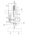
- Drawing 1 is a front view showing terminal crimping device 10 concerning an embodiment.
- FIG. 2 is a schematic cross-sectional view showing the terminal crimping apparatus 10 according to the embodiment.
- the terminal crimping apparatus 10 is an apparatus for manufacturing the terminal-attached electric wire 100 by crimping the terminal 80 to the electric wire 90.
- the terminal crimping apparatus 10 includes a crimping unit 20 that crimps and fixes an end of the electric wire 90 to a terminal 80 (specifically, a barrel 82 of the terminal 80).
- the terminal crimping device 10 will be described as one that separates one terminal 80 from the continuous terminal and crimps it to the electric wire 90.
- the continuous terminal is a band-shaped member in which a plurality of terminals 80 are connected. Specifically, the continuous terminal is formed by connecting a plurality of terminals 80 in parallel at equal intervals on one side of a strip-shaped carrier 80c. Feed holes are formed in the carrier 80c at equal intervals corresponding to the terminals 80.
- the base part of each terminal 80 on the carrier 80c side is a barrel 82, and is formed to be open in a substantially U-shaped cross section so that it can be crimped to the end of the electric wire 90.
- a wire barrel 83 that is crimped to the core wire 92 of the electric wire 90 and an insulation barrel 84 that is crimped to the covering 94 of the electric wire 90 are provided.
- the terminal 80 is provided with a connecting portion 86 for connecting to the counterpart conductor at the tip of the barrel 82.
- the connecting portion 86 is formed in a box shape, but this is not essential.
- the connection part 86 should just be formed in a well-known various shape.
- the terminal crimping device 10 may further include a terminal feeding unit (terminal feeding device).
- the terminal feeding portion is a portion that feeds out a long continuous terminal wound in a reel shape and feeds it to the crimping portion 20 by one terminal 80.
- cooperate, and it has a structure which performs a crimping
- the terminal feed unit includes, for example, a route defining unit that regulates the delivery path of the continuous terminal, a delivery unit that delivers the continuous terminal along the delivery route, and an interlocking mechanism that links the movement of the crimping unit 20 and the movement of the delivery unit. It is possible to prepare
- the route defining portion includes a long plate-like stage extending toward the crimping portion 20.
- the upper surface of the stage is disposed in a horizontal plane, and the upper surface functions as a guide surface that guides the continuous terminal to the crimping portion 20.
- the sending part has a feeding claw.
- the feeding claw is a long member, and is disposed above the passing region of the carrier 80c on the stage.
- the feed claw is supported by a swing member described later so as to be swingable.
- a claw portion is provided at one end of the feed claw.
- the claw portion has a tapered shape as it goes to the tip, and the tip is configured to be able to be caught in a feed hole formed in the carrier 80c of the continuous terminal on the stage.
- the feed part is configured so that the claw part is caught in the feed hole only when the feed claw moves in the feed direction, and the claw part is not caught in the feed hole when the feed claw moves in the return direction opposite to the feed direction. Has been.
- the interlocking mechanism is a mechanism that interlocks the movement of the crimping part 20 (specifically, the lifting / lowering movement of the shank part 24) and the movement of the sending part (specifically, the reciprocating movement of the feeding claw).
- the interlocking mechanism interlocks both so that the feed claw moves in the feed direction when the shank portion 24 rises and the feed claw moves in the return direction when the shank portion 24 descends.
- the crimping unit 20 crimps the terminal 80 to the electric wire 90 by crimping one terminal 80 of the plurality of terminals 80 connected to the continuous terminal with a mold.
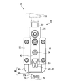
- the crimping portion 20 includes a shank portion 24, a ram 22, an upper die for crimping (crimpers 28, 30), and a lower die for crimping (anvil 70). Furthermore, the crimping
- the crimping unit 20 includes a plurality of urging members 60.
- the shank portion 24 is formed in a substantially rectangular parallelepiped shape that can be disposed between the pair of guide frame pieces 12, and the width dimension thereof is narrower than the interval dimension between the pair of guide frame pieces 12 (here, slightly smaller). Narrow). The shank portion 24 is guided between the pair of guide frame pieces 12 in a fixed posture so as to be movable up and down between the raised position and the lowered position.
- the ram 22 is formed so as to transmit the driving force of the elevating drive mechanism 110 disposed above the shank part 24 to the shank part 24.
- the raising / lowering drive mechanism is comprised by actuators, such as an air cylinder, for example. Therefore, the shank portion 24 moves up and down by receiving the driving force of the lifting drive mechanism portion 110 via the ram 22.
- the cut-off punch 40, the wire pressing member 50, and the crimpers 28 and 30 are attached to the shank portion 24 via the support shaft 26 and move up and down in conjunction with the shank portion 24.
- the crimpers 28 and 30 are attached to the lower part of the shank portion 24.
- the anvil 70 is attached at a position below the shank portion 24 and facing the crimpers 28 and 30.
- the crimpers 28 and 30 include the wire crimper 28 that crimps the wire barrel 83 and the insulation crimper 30 that crimps the insulation barrel 84.
- Each crimper 28, 30 has a groove formed on the surface on the anvil 70 side. The inner surface of the groove is formed in a shape that can be crimped while guiding the tip of the barrel 82 so as to gradually fall toward the core wire 92.
- the insulation crimper 30 of the crimpers 28 and 30 will be described in detail later together with the cutoff punch 40 and the wire pressing member 50.
- the cutter 72 is a part for cutting the terminal 80 from the carrier 80c.
- the cutter 72 is supported by a frame or the like so as to be swingable in the vertical direction.
- the cutter 72 is formed with a groove 73 that can accommodate the carrier 80c.
- the groove 73 is formed so that the anvil 70 side opens.
- the cut-off punch 40 is a member that pushes the cutter 72.
- the cut-off punch is attached to the shank portion 24 via the support shaft 26.
- the cut-off punch 40 will be described in detail later together with the insulation crimper 30 and the wire pressing member 50.
- the wire holding member 50 is a member that holds the electric wire 90 so that the electric wire 90 is not displaced during crimping.
- the wire pressing member 50 is attached to the shank portion 24 via the support shaft 26. The wire pressing member 50 will be described later in detail together with the insulation crimper 30 and the cut-off punch 40.
- the stripper 74 is a member that pulls away the terminal 80 that has bitten into the crimper when the biting of the terminal 80 is not eliminated by the contact member 30 described later.
- the stripper 74 is attached to a frame or the like and is provided so as not to interlock with the shank portion 24.
- the stripper 74 is connected to each guide frame piece 12 so that the stripper 74 extends downward from each guide frame piece 12 and a connecting part 74b that connects the ends of the pair of extension parts 74a. Including. An intermediate portion of the connecting portion 74 b comes into contact with the terminal 80.
- the stripper 74 is provided at a position where it can come into contact with a tip side portion of the terminal 80 from the wire barrel 83 (here, a portion between the connecting portion 86 and the wire barrel 83). But the position which the stripper 74 contact
- the stripper 74 may be in contact with the connection portion 86 or may be in contact with a rear end side portion of the wire barrel 83.
- the crimper attached to the shank part 24, the cut-off punch 40, and the wire pressing member 50 are moved up and down by moving the shank part 24 up and down. That is, the crimpers 28 and 30 move closer to and away from the anvil 70 as the shank portion 24 is moved up and down.
- the crimpers 28, 30 move close to the anvil 70 and are disposed on the anvil 70 between the crimpers 28, 30 and the anvil 70.
- the barrel 82 of the terminal 80 is crimped and crimped to the end of the electric wire 90.
- the cut-off punch depresses the cutter 72, and the cutter 72 cuts the terminal 80 from the carrier 80c.
- the wire pressing member 50 presses the electric wire 90 so that the electric wire 90 arranged on the cutter 72 is not displaced.
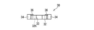
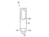
- FIG. 3 is a front view showing the insulation crimper 30.
- FIG. 4 is a bottom view showing the insulation crimper 30.
- FIG. 5 is a side view showing the insulation crimper 30.
- the crimpers 28 and 30 are worn by repeated use, and the terminal 80 is likely to bite.
- the wire crimper 28 presses the metal barrel 82 to the metal core 92
- the wire crimper 28 is more easily worn than the insulation crimper 30 that presses the metal barrel 82 to the resin coating 94.
- the terminal 80 tends to bite into the wire crimper 28 rather than the insulation crimper 30.
- the wire crimper 28 is desired to have high crimping accuracy in order to surely connect the wire barrel 83 and the core wire 92, it is difficult to adopt a structure for preventing the wire crimper 28 from biting.
- a member such as a stripper 74 is separately provided to eliminate the bite.
- the stripper 74 comes into contact with the terminal 80 that bites the wire crimper 28 that rises together with the ram 22, the force applied to the terminal 80 increases, and the terminal 80 bends when the force for biting is large. There was a fear. More specifically, the force from the stripper 74 acts in a downward direction with respect to the terminal 80, and tries to rotate the terminal 80 around the bitten portion.
- the biting of the terminal 80 is weak, the biting is eliminated without rotating or while rotating.
- the biting of the terminal 80 is strong, the terminal 80 is bent and deformed without rotating or partially rotating. Therefore, in the present invention, the impact is weakened by providing the contact member 30 separately from the stripper 74 and urging the contact member 30 with the urging member 60.
- the contact member 30 is a member that contacts the terminal-attached electric wire 100 in a state where the terminal 80 bites into the wire crimper 28 while the terminal-attached electric wire 100 takes the same crimping posture as that at the time of crimping.
- the crimping posture of the terminal-attached electric wire 100 is a posture in which the terminal-attached electric wire 100 is taken with respect to the wire crimper 28 at the time of crimping, and here is a posture in which the terminal-attached electric wire 100 extends in the horizontal direction. .
- the contact member 30 moves in the crimping direction in conjunction with the ram 22 that moves the wire crimper 28 up and down, and is in contact with the terminal-attached electric wire 100 with the ram 22 positioned at the bottom dead center.
- the urging member 60 urges the abutting member 30 in a state where the ram 22 is located at the bottom dead center and the abutting member 30 is in contact with the electric wire 100 with a terminal.
- the contact member 30 is preferably in contact with the rear end side of the terminal-attached electric wire 100 with respect to the connection portion 86.
- the insulation crimper 30 plays a role as the contact member 30 in addition to the original role of crimping the insulation barrel 84.
- the insulation crimper 30 includes a crimper body portion 32, a protrusion 34, and a rib 36.
- the crimper main body 32 is formed in a rectangular plate shape, and the groove 33 for crimping the insulation barrel 84 is formed on the lower end surface. Further, the crimper main body portion 32 is formed with a through hole 32h through which the support shaft 26 is inserted.
- the through hole 32 h is formed so as to penetrate both main surfaces of the crimper main body 32.
- the through hole 32h is a long hole in the vertical direction. Here, it is formed in such a shape that a rectangular hole is located between two semicircular holes. Further, the radius of the semicircular hole is formed larger than the radius of the support shaft 26.
- the insulation crimper 30 can be adjusted in height, and play is produced during crimping. That is, the height of the insulation crimper 30 can be adjusted with respect to the support shaft 26.
- the height adjustment is performed, for example, by the adjustment member pressing the upper surface of the crimper main body 32 at a different height.
- the insulation crimper 30 is supported by the support shaft 26 so as to be swingable in the vertical direction with respect to the support shaft 26. And here, the 1st biasing member 62 mentioned later is elastically deformed using this play. This will be described in detail later.
- a pair of protrusions 34 are formed so as to protrude from the intermediate part of the crimper main body 32 to both sides.
- Each protrusion 34 is arranged between the protrusions 34 of the cut-off punch 40, and the movement is restricted by the protrusion 34 and the protrusion 34 coming into contact with each other.
- a first biasing member 62 is disposed on the upper surface of each protrusion 34.
- the rib 36 is erected on one main surface side at the side edge of the crimper main body 32.
- the ribs 36 are respectively provided on both sides of the crimper main body 32.
- the thickness of the portion of the crimper main body 32 where the ribs 36 are formed and the protrusion 34 are set to be the same. Thereby, the 1st biasing member 62 distribute
- the rib 36 also plays a role of suppressing a decrease in rigidity caused by reducing the width dimension of the crimper main body portion 32 when the first urging member 62 is disposed on the upper surface of the protrusion 34.
- the distance between the pair of ribs 36 is set to be approximately the same as the width dimension of the presser main body 52 of the wire presser. Between the pair of ribs 36, a presser main body 52, which will be described later, of the wire presser is disposed.
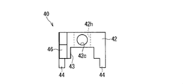
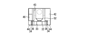
- FIG. 6 is a front view showing the cutoff punch 40.
- FIG. 7 is a bottom view showing the cutoff punch 40.
- FIG. 8 is a side view showing the cutoff punch 40.
- the cut-off punch 40 is a member that presses the cutter 72.
- the cut-off punch includes a punch main body portion 42, a protruding portion 44, and a pressing portion 46.
- the punch main body 42 is formed in a rectangular parallelepiped shape.
- the punch main body portion 42 is formed with a through hole 42h through which the support shaft 26 is inserted.
- the punch main body 42 is formed with a groove 43 in which the presser main body 52 of the wire pressing member 50 is disposed.
- the punch main body 42 is formed with a hole 42c in which a second urging member 64 for urging the wire pressing member 50 is disposed.
- the through-hole 42 h is formed so as to penetrate both main surfaces of the punch main body 42 at substantially the center of the main surface of the punch main body 42.
- the through hole 42 h is formed in a circular shape, and the diameter thereof is set to be approximately the same as the diameter of the support shaft 26.
- the cut-off punch 40 is supported by the support shaft 26 so as to be movable up and down integrally with the ram 22.
- the groove 43 is formed on one main surface side of the punch main body 42.
- the groove 43 is formed so as to extend along the height direction of the punch main body 42 (the vertical direction in FIG. 6).
- the width dimension of the groove 43 along the width direction (the left-right direction in FIG. 6) of the punch main body portion 42 is set to be approximately the same as the width dimension of the presser main body portion 52 of the wire pressing member 50, as is the interval between the pair of ribs 36. Has been.
- the hole 42c is formed substantially at the center of the bottom surface of the punch main body 42.
- the hole 42c is formed in a circular shape.
- the diameter of the hole 42c is slightly larger than the diameter of the compression coil spring 64 used as the second urging member 64.
- the protrusions 44 are respectively formed at four corners of one main surface (the main surface on the side where the groove 43 is formed) of the punch main body 42. Each protrusion 44 is formed in a rectangular parallelepiped shape, and all have the same shape.
- the interval between the two protrusions 44 positioned on the left and right of the punch main body 42 is set to be equal to or larger than the width dimension of the crimper main body 32 and equal to or smaller than the interval between the outer surfaces of the protrusions 34.
- the distance between the two protrusions 44 positioned above and below the punch main body 42 is larger than the height of the protrusion 34, and the sum of the height of the protrusion 34 and the free length of the first biasing member 62. It is set smaller.
- the crimper main body 32 is interposed between the two protrusions 44 positioned on the left and right of the punch main body 42 in a state where the cut-off punch 40 and the insulation crimper 30 are combined.
- a protrusion 34 is disposed between the two protrusions 44 positioned above and below the punch main body 42.
- a first urging member 62 is disposed between the upper surface of the protrusion 34 and the lower surface of the upper protrusion 44. At this time, the first urging member 62 is arranged in a compressed state.
- the lower protrusion 44 abuts against the lower surface of the protrusion 34 when the insulation crimper 30 descends with respect to the cut-off punch 40 and restricts its movement.
- the protrusion 34 and the lower protrusion 44 are in contact with each other, and this is the initial position.
- the insulation crimper 30 eventually comes into contact with the insulation barrel 84 and starts crimping the insulation barrel 84.
- the insulation crimper 30 receives a reaction force related to the crimping. This reaction force is transmitted to the first urging member 62 and the first urging member 62 is compressed, so that the lowering amount of the insulation crimper 30 becomes smaller than the lowering amount of the support shaft 26 and the cut-off punch 40, and the supporting force is reduced.
- the shaft 26 and the cut-off punch 40 are raised to the height set by the height adjustment.
- the insulation crimper 30 is raised to the height set for the spindle 26 and the cut-off punch 40, the insulation barrel 84 is crimped to the covering 94. At this time, the first urging member 62 is not further compressed.
- the pressing portion 46 is formed so as to protrude below the lower surface of the punch main body portion 42.
- the pressing portion 46 is formed on one side of the punch main body portion 42.
- the pressing part 46 presses the pressed part 72 a of the cutter 72 and pushes down the cutter 72.
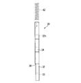
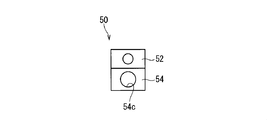
- FIG. 9 is a front view showing the wire pressing member 50.
- FIG. 10 is a plan view showing the wire pressing member 50.
- FIG. 11 is a side view showing the wire pressing member 50.
- the wire holding member 50 is a member that holds the electric wire 90 so that the electric wire 90 is not displaced during crimping.
- the wire pressing member 50 presses the electric wire 90 toward the upper surface of the cutter 72, for example.
- the wire presser member 50 includes a presser main body portion 52 and a support portion 54.
- the presser body 52 is formed in a rectangular plate shape.
- the presser main body 52 is formed in such a manner that, on one end side in the height direction, both side portions are inclined so that the width dimension gradually decreases toward the tip.
- the presser main body 52 is formed in such a manner that the one main surface side portion is inclined so that the thickness dimension gradually decreases toward the tip at one end in the height direction.
- a through hole 52 h for inserting the support shaft 26 is formed on the other end side in the height direction of the presser body portion 52.
- a groove 53 for pressing the electric wire 90 is formed on the lower surface on one end side in the height direction of the presser body portion 52.
- the through hole 52h is formed so as to penetrate both main surfaces of the presser main body 52.
- the through hole 52h is a long hole in the vertical direction. Here, it is formed in such a shape that a rectangular hole is located between two semicircular holes.
- the radius of the semicircular hole is the same as the radius of the support shaft 26. Accordingly, the wire pressing member 50 is supported so as to be swingable in the vertical direction with respect to the support shaft 26.
- the groove 53 is formed at the center in the width direction of the presser body portion 52 and is formed in an isosceles triangle shape in front view.
- the electric wire 90 is positioned by sandwiching the electric wire 90 between the inner surface of the groove 53 and the upper surface of the cutter 72.
- the width dimension of the presser body 52 is set to be the same as the width dimension of the groove 43 along the width direction of the punch body 42.
- the presser body portion 52 is disposed in the groove 43 and is movable in the vertical direction along the groove 43.
- the thickness dimension of the presser body 52 is set to be larger than the depth dimension of the groove 43 along the thickness direction (vertical direction in FIG. 7) of the punch body 42, so that a part protrudes from the groove 43. Is formed.
- This protruding portion is disposed between the ribs 36 of the insulation crimper 30. For this reason, the movement of the insulation crimper 30 is restricted so as to move in the vertical direction with respect to the wire pressing member 50.
- the support portion 54 is a portion that supports the second urging member 64 disposed between the cut-off punch 40.
- the support portion 54 is formed so as to protrude from one end side in the height direction of the presser body portion 52 to the one main surface side.
- the support portion 54 is formed in a rectangular parallelepiped shape, and a hole 54c is formed on the upper surface thereof.
- the hole 54c is formed in a circular shape.
- the hole 54c is formed in the same shape as the hole 42c formed in the cut-off punch 40 in plan view. With the cut-off punch 40 and the wire pressing member 50 supported by the support shaft 26, the hole 42c and the hole 54c are located at the same position on the horizontal plane.
- the compression coil spring 64 is disposed between the cut-off punch 40 and the wire pressing member 50 in a compressed state in such a manner that both ends of the compression coil spring 64 are supported by the hole 42c and the hole 54c, respectively. Thus, the wire pressing member 50 is urged downward.
- the wire pressing member 50 is positioned below the support shaft 26 and the cut-off punch 40 within a swingable range before being crimped.
- the wire pressing member 50 contacts the electric wire 90 before the cut-off punch 40 contacts the cutter 72.
- the compression coil spring 64 is compressed, the amount of lowering of the wire pressing member 50 becomes smaller than the amount of lowering of the support shaft 26 and the cut-off punch 40, and the wire pressing member 50 is supported.
- the shaft 26 and the cut-off punch 40 are raised.
- the urging member 60 includes a first urging member 62 disposed between the cut-off punch 40 and the insulation crimper 30 and a second urging member disposed between the cut-off punch 40 and the wire pressing member 50. Member 64.
- the first urging member 62 urges the abutting member (insulation crimper) 30 that abuts on the terminal-attached electric wire 100 in a crimping posture with an urging force that can eliminate at least a part of the biting of the terminal 80.
- two compression coil springs 62 are employed as the first urging member 62.
- the two compression coil springs 62 are provided in parallel so as to share the urging force.
- the two compression coil springs 62 are arranged on the upper surfaces of the protrusions 34 provided on both sides of the crimper main body 32 of the insulation crimper 30, so that the urging force can be shared in parallel. Is provided.
- the two compression coil springs 62 are provided at symmetrical positions with respect to the position of the insulation crimper 30 in contact with the insulation barrel 84, the posture of the insulation crimper 30 is stabilized.
- the second urging member 64 urges the wire pressing member 50 with an urging force that allows the wire pressing member 50 to press the electric wire 90 so that the electric wire 90 is not displaced during crimping.
- a compression coil spring 64 is employed as the second urging member 64.
- the second urging member 64 is in the most compressed state with the ram 22 positioned at the bottom dead center. Accordingly, since the second urging member 64 also presses the terminal-attached electric wire 100 in a state where the ram 22 is located at the bottom dead center, the second urging member 64 causes the first urging member 62 to bite the terminal 80. It is conceivable that it is helpful in demonstrating the urging power to be eliminated. However, when only the second urging member 64 is employed without adopting the first urging member 62, the second urging member 64 does not generate an urging force that can eliminate the biting of the terminal 80.
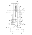
- FIG. 15 is a front view schematically showing a state of the crimping portion 20 when the ram 22 is located at the bottom dead center.
- FIG. 16 is a side view schematically showing a state of the crimping portion 20 when the ram 22 is located at the bottom dead center.
- FIGS. 17 to 19 are side views schematically illustrating how the biting of the terminal 80 is eliminated.
- the terminal 80 to be crimped is disposed at the crimping position by the terminal feeding portion.
- the electric wire 90 is also arranged at the crimping position by an electric wire transfer device (not shown).
- the crimpers 28 and 30 and the barrel 82 come into contact with each other.
- the barrel 82 is crimped to the end of the electric wire 90 by the crimpers 28 and 30.
- the first urging member 62 is compressed, and in response to this, the insulation crimper 30 presses the insulation barrel 84 toward the anvil 70.
- the urging force from the insulation crimper 30 is absorbed by the anvil 70.
- the second urging member 64 is also compressed, and in response to this, the wire pressing member 50 presses the portion of the electric wire 90 extending from the barrel 82 toward the cutter 72.
- the wire crimper 28 follows the ram 22 and rises. At this time, if the terminal 80 does not bite into the wire crimper 28, the terminal 80 remains placed on the anvil 70 without rising.
- the terminal 80 bites into the wire crimper 28
- the terminal 80 also rises together with the wire crimper 28.
- the insulation crimper 30 tries to stay in place without following the ram 22 by the compression of the first urging member 62 being relaxed. Accordingly, the insulation crimper 30 receives the urging force from the first urging member 62 and keeps the terminal 80 pressed toward the anvil 70. Therefore, when the terminal 80 bites into the wire crimper 28, an upward force from the wire crimper 28 is applied to the wire barrel 83 and a downward force from the insulation crimper 30 is applied to the installation barrel 84.
- the terminal 80 is located at a position in contact with the anvil 70 or a position slightly lifted from the anvil 70, even if the terminal 80 is deformed by receiving these forces, the deformation amount is small. Most of the force tends to act as a force that pulls the terminal 80 away from the wire crimper 28. When the pressing force is sufficiently larger than the force related to the biting of the terminal 80, the biting of the terminal 80 is completely eliminated.
- the biting of the terminal 80 is not completely eliminated even when the ram 22 is slightly raised, the terminal 80 is lifted while the wire barrel 83 is stuck to the wire crimper 28 and the installation barrel 84 is removed from the installation crimper 30. Therefore, it is considered that the wire barrel 83 is slightly rotated around the wire barrel 83 as shown in FIG. In this case, the biting of the terminal 80 may or may not be completely eliminated by further raising the ram 22.
- the insulation crimper 30 cannot press the terminal 80 in the middle of returning the insulation crimper 30 to the initial position with respect to the support shaft 26. It is also possible to stop relative to the shaft 26. Further, as shown in FIG. 18, the terminal 80 receives a force from the insulation crimper 30 and further rotates around the portion that bites the wire crimper 28, so that the insulation crimper 30 is initially moved with respect to the support shaft 26. It can also return to position.
- the terminal 80 rises together with the wire crimper 28 and eventually comes into contact with the stripper 74 as shown in FIG. As a result, the biting of the terminal 80 is completely eliminated. Even in this case, since the biting of the terminal 80 is partially eliminated, the biting of the terminal 80 is weakened. For this reason, even if the force received by the terminal 80 from the stripper 74 is the same as the conventional one, the terminal 80 is easily prevented from being bitten, so that deformation is hardly caused.
- the terminal 80 rises while abutting on the insulation crimper 30 and also abuts on the stripper 74, the terminal 80 is pressed at two positions sandwiching the wire barrel 83, so that the biting is more easily eliminated. 80 becomes difficult to deform.
- the second urging member 64 is disposed between the wire pressing member 50 and the cut-off punch 40, the force applied to the wire pressing member 50 on the terminal-attached electric wire 100 is different, but is the same as that of the insulation crimper 30. Perform the operation. Therefore, the wire pressing member 50 can be regarded as helping the insulation crimper 30 to eliminate the biting of the terminal 80.
- the insulation crimper 30 receives at least a part of the biting of the terminal 80 by receiving the biasing force of the first biasing member 62. For this reason, since it is suppressed that a strong force is applied to the terminal 80 suddenly, even when the terminal 80 bites strongly against the wire crimper 28, the biting is eliminated while suppressing deformation of the terminal 80. Can do.
- the wire crimper 28 since the urging force is applied at the bottom dead center where the terminal 80 is sandwiched between the wire crimper 28 and the anvil 70, the wire crimper 28 starts to move from the bottom dead center to the top dead center and starts to move away from the anvil 70.
- the bite can be resolved at the stage where Thereby, deformation of the terminal 80 can be suppressed by the anvil 70.
- the terminal 80 When the connecting portion 86 is pressed against the terminal 80, the terminal 80 is easily bent between the connecting portion 86 and the wire barrel 83. On the other hand, according to the present invention, since the insulation crimper 30 abuts the rear end side of the connecting portion 86 in the terminal-attached electric wire 100, the terminal 80 is hardly deformed.
- the insulation crimper 30 abuts against the insulation barrel 84 of the terminal 80 having higher rigidity than the electric wire 90, the urging force is less likely to be dispersed than when the insulation crimper 30 abuts against the electric wire 90.
- the insulation barrel 84 receives the biasing force, so that the electric wire 90 is not easily damaged.
- the insulation barrel 84 is located on the rear end side of the wire barrel 83, the terminal 80 can be prevented from being bent between the connection portion 86 and the wire barrel 83. Further, by using the insulation crimper 30 together as the contact member 30, it is not necessary to provide another member.
- the compression coil spring 62 is disposed between the cut-off punch 40 and the insulation crimper 30, the urging force can be supported by the cut-off punch 40.
- the members are densely packed in the vicinity of the crimping portion 20, it is difficult to secure a space for disposing if the biasing member is large. At this time, if an attempt is made to reduce the size by increasing the spring constant, the cost may increase. Even in this case, one urging member 62 can be made smaller by sharing the urging force with the plurality of first urging members 62. In addition, an increase in cost can be suppressed by suppressing an increase in the spring constant.
- the contact member 30 is the insulation crimper 30
- the wire pressing member 50 can be considered as the contact member.
- a large urging force is generated in the second urging member 64.
- the reformer 76 is a member that adjusts the box shape of the terminal 80.
- the reformer 76 is also a member that is supported by the support shaft 26 and interlocks with the ram 22.
- a plurality of members may be provided as the abutting members, and urging members may be individually provided for the plurality of members, and the biting may be eliminated by adding the urging forces applied to the plurality of abutting members.
- the urging force may be eliminated by the combined urging force even if the urging force cannot be eliminated by the respective urging forces alone. .
- first urging member 62 and the second urging member 64 have been described as adopting compression coil springs, but this is not essential.
- another spring such as a tension coil spring may be employed, or a member formed of an elastic material such as a rubber-like member may be employed.
Landscapes
- Engineering & Computer Science (AREA)
- Manufacturing & Machinery (AREA)
- Manufacturing Of Electrical Connectors (AREA)
Abstract
La présente invention concerne une technique qui permet d'éliminer la morsure tout en empêchant une déformation d'une borne, même si une borne mord fortement dans un appareil de sertissage. La présente invention concerne un dispositif de sertissage de borne destiné à produire un fil équipé d'une borne par sertissage de la borne sur le fil. Le dispositif de sertissage de borne comporte : une enclume sur laquelle sont placés le fil et la borne ; un appareil de sertissage de fil destiné à sertir une gaine de fil de la borne sur une âme du fil ; un élément de butée ; et un élément de poussée. L'élément de butée vient en butée contre le fil équipé d'une borne dans un état dans lequel la borne mord dans l'appareil de sertissage tandis que le fil équipé d'une borne prend la même orientation de sertissage que pendant un sertissage. L'élément de poussée pousse l'élément de butée, venant en butée contre le fil équipé d'une borne qui prend l'orientation de sertissage, avec une force de poussée qui peut éliminer au moins une partie de la morsure de la borne.
Applications Claiming Priority (2)
| Application Number | Priority Date | Filing Date | Title |
|---|---|---|---|
| JP2016032877A JP2017152179A (ja) | 2016-02-24 | 2016-02-24 | 端子圧着装置 |
| JP2016-032877 | 2016-02-24 |
Publications (1)
| Publication Number | Publication Date |
|---|---|
| WO2017145890A1 true WO2017145890A1 (fr) | 2017-08-31 |
Family
ID=59686113
Family Applications (1)
| Application Number | Title | Priority Date | Filing Date |
|---|---|---|---|
| PCT/JP2017/005499 Ceased WO2017145890A1 (fr) | 2016-02-24 | 2017-02-15 | Dispositif de sertissage de borne |
Country Status (2)
| Country | Link |
|---|---|
| JP (1) | JP2017152179A (fr) |
| WO (1) | WO2017145890A1 (fr) |
Families Citing this family (1)
| Publication number | Priority date | Publication date | Assignee | Title |
|---|---|---|---|---|
| JP6895351B2 (ja) * | 2017-09-11 | 2021-06-30 | 矢崎総業株式会社 | 端子圧着装置 |
Citations (6)
| Publication number | Priority date | Publication date | Assignee | Title |
|---|---|---|---|---|
| JPS509785A (fr) * | 1973-05-31 | 1975-01-31 | ||
| JPS61104577A (ja) * | 1984-10-27 | 1986-05-22 | 住友電気工業株式会社 | 圧着端子の圧着離型機構 |
| JPH01206588A (ja) * | 1987-10-20 | 1989-08-18 | Yazaki Corp | ターミナル圧着装置 |
| JPH0553189U (ja) * | 1991-12-21 | 1993-07-13 | 住友電装株式会社 | 端子の圧着金型 |
| JPH1167415A (ja) * | 1997-08-27 | 1999-03-09 | Sumitomo Wiring Syst Ltd | クリンパー組立体 |
| JP2000021544A (ja) * | 1998-07-07 | 2000-01-21 | Amp Japan Ltd | 電線圧着装置 |
-
2016
- 2016-02-24 JP JP2016032877A patent/JP2017152179A/ja active Pending
-
2017
- 2017-02-15 WO PCT/JP2017/005499 patent/WO2017145890A1/fr not_active Ceased
Patent Citations (6)
| Publication number | Priority date | Publication date | Assignee | Title |
|---|---|---|---|---|
| JPS509785A (fr) * | 1973-05-31 | 1975-01-31 | ||
| JPS61104577A (ja) * | 1984-10-27 | 1986-05-22 | 住友電気工業株式会社 | 圧着端子の圧着離型機構 |
| JPH01206588A (ja) * | 1987-10-20 | 1989-08-18 | Yazaki Corp | ターミナル圧着装置 |
| JPH0553189U (ja) * | 1991-12-21 | 1993-07-13 | 住友電装株式会社 | 端子の圧着金型 |
| JPH1167415A (ja) * | 1997-08-27 | 1999-03-09 | Sumitomo Wiring Syst Ltd | クリンパー組立体 |
| JP2000021544A (ja) * | 1998-07-07 | 2000-01-21 | Amp Japan Ltd | 電線圧着装置 |
Also Published As
| Publication number | Publication date |
|---|---|
| JP2017152179A (ja) | 2017-08-31 |
Similar Documents
| Publication | Publication Date | Title |
|---|---|---|
| US10424891B2 (en) | Wire crimping device | |
| JP6434950B2 (ja) | 端子圧着装置 | |
| US10103455B2 (en) | Crimp terminal and terminal crimping method | |
| CN109037975B (zh) | 带端子的电线以及端子压接装置 | |
| US10511131B2 (en) | Terminal crimping device | |
| CN105846275B (zh) | 端子压接装置 | |
| JP4636013B2 (ja) | 端子圧着装置 | |
| JP2016149196A (ja) | 端子圧着装置 | |
| US9742101B2 (en) | Crimp terminal | |
| JP2013089554A (ja) | 端子付き電線、端子付き電線の製造方法および端子圧着装置 | |
| JP6404295B2 (ja) | 端子圧着装置 | |
| CN107946782B (zh) | 带端子的电线、带端子的电线的制造方法和端子压接装置 | |
| WO2017145890A1 (fr) | Dispositif de sertissage de borne | |
| US20160226208A1 (en) | Crimping device with seal depressor | |
| WO2016125564A1 (fr) | Appareil de sertissage de borne et procédé de fabrication de fil électrique avec borne | |
| US20230378705A1 (en) | Terminal crimping apparatus | |
| JP2010015701A (ja) | 端子圧着装置 | |
| JP3885510B2 (ja) | クランプバネの製造方法 | |
| JP6117256B2 (ja) | 端子圧着装置 | |
| US10923871B2 (en) | Manufacturing method of crimping terminal | |
| JP5506278B2 (ja) | 端子圧着装置 | |
| JP6314848B2 (ja) | プレス用成形型 | |
| WO2013061633A1 (fr) | Dispositif de sertissage de bornes | |
| JP6867903B2 (ja) | 端子付き電線、端子圧着用金型および端子付き電線の製造方法 | |
| WO2022044648A1 (fr) | Dispositif de sertissage |
Legal Events
| Date | Code | Title | Description |
|---|---|---|---|
| NENP | Non-entry into the national phase |
Ref country code: DE |
|
| 121 | Ep: the epo has been informed by wipo that ep was designated in this application |
Ref document number: 17756330 Country of ref document: EP Kind code of ref document: A1 |
|
| 122 | Ep: pct application non-entry in european phase |
Ref document number: 17756330 Country of ref document: EP Kind code of ref document: A1 |