WO2017146019A1 - 成形材製造方法及びその成形材 - Google Patents
成形材製造方法及びその成形材 Download PDFInfo
- Publication number
- WO2017146019A1 WO2017146019A1 PCT/JP2017/006292 JP2017006292W WO2017146019A1 WO 2017146019 A1 WO2017146019 A1 WO 2017146019A1 JP 2017006292 W JP2017006292 W JP 2017006292W WO 2017146019 A1 WO2017146019 A1 WO 2017146019A1
- Authority
- WO
- WIPO (PCT)
- Prior art keywords
- die
- molding material
- flange portion
- metal plate
- punch
- Prior art date
- Legal status (The legal status is an assumption and is not a legal conclusion. Google has not performed a legal analysis and makes no representation as to the accuracy of the status listed.)
- Ceased
Links
Images


Classifications
-
- B—PERFORMING OPERATIONS; TRANSPORTING
- B21—MECHANICAL METAL-WORKING WITHOUT ESSENTIALLY REMOVING MATERIAL; PUNCHING METAL
- B21D—WORKING OR PROCESSING OF SHEET METAL OR METAL TUBES, RODS OR PROFILES WITHOUT ESSENTIALLY REMOVING MATERIAL; PUNCHING METAL
- B21D22/00—Shaping without cutting, by stamping, spinning, or deep-drawing
- B21D22/20—Deep-drawing
- B21D22/28—Deep-drawing of cylindrical articles using consecutive dies
-
- B—PERFORMING OPERATIONS; TRANSPORTING
- B21—MECHANICAL METAL-WORKING WITHOUT ESSENTIALLY REMOVING MATERIAL; PUNCHING METAL
- B21D—WORKING OR PROCESSING OF SHEET METAL OR METAL TUBES, RODS OR PROFILES WITHOUT ESSENTIALLY REMOVING MATERIAL; PUNCHING METAL
- B21D22/00—Shaping without cutting, by stamping, spinning, or deep-drawing
- B21D22/20—Deep-drawing
- B21D22/206—Deep-drawing articles from a strip in several steps, the articles being coherent with the strip during the operation
-
- B—PERFORMING OPERATIONS; TRANSPORTING
- B21—MECHANICAL METAL-WORKING WITHOUT ESSENTIALLY REMOVING MATERIAL; PUNCHING METAL
- B21D—WORKING OR PROCESSING OF SHEET METAL OR METAL TUBES, RODS OR PROFILES WITHOUT ESSENTIALLY REMOVING MATERIAL; PUNCHING METAL
- B21D22/00—Shaping without cutting, by stamping, spinning, or deep-drawing
- B21D22/20—Deep-drawing
- B21D22/21—Deep-drawing without fixing the border of the blank
-
- B—PERFORMING OPERATIONS; TRANSPORTING
- B21—MECHANICAL METAL-WORKING WITHOUT ESSENTIALLY REMOVING MATERIAL; PUNCHING METAL
- B21D—WORKING OR PROCESSING OF SHEET METAL OR METAL TUBES, RODS OR PROFILES WITHOUT ESSENTIALLY REMOVING MATERIAL; PUNCHING METAL
- B21D22/00—Shaping without cutting, by stamping, spinning, or deep-drawing
- B21D22/20—Deep-drawing
- B21D22/22—Deep-drawing with devices for holding the edge of the blanks
Definitions
- the present invention relates to a molding material manufacturing method for manufacturing a molding material having a cylindrical body portion and a flange portion formed at an end portion of the body portion, and the molding material.
- Non-Patent Document 1 by performing drawing processing, a molding material having a cylindrical body portion and a flange portion formed at an end portion of the body portion is manufactured. Has been done.
- the plate thickness of the body portion becomes smaller than the material plate thickness.
- the region corresponding to the flange portion of the material metal plate shrinks as a whole in accordance with the formation of the body portion, the plate thickness of the flange portion is larger than the plate thickness of the material.
- the material may be referred to as “blank”.
- the molding material as described above may be used as a motor case shown in Patent Document 1 below.
- the trunk portion is expected to have a performance as a shield material that prevents magnetic leakage outside the motor case.
- the performance of the stator as a back yoke is also expected from the body.
- the performance as a shield material or a back yoke becomes better as the plate thickness of the body portion increases. For this reason, as described above, when manufacturing a molding material by drawing, a material metal plate that is thicker than the required plate thickness of the barrel is selected in consideration of the reduction in the plate thickness of the barrel by drawing. Is done.
- the flange portion is often used for attaching the motor case to an attachment target. For this reason, it is expected that the flange portion has a certain amount of strength.
- a molding material having a cylindrical body portion and a flange portion formed at the end portion of the body portion is manufactured by drawing, so that the flange portion The plate thickness is larger than the material plate thickness. For this reason, the flange portion may be unnecessarily thick beyond the plate thickness that satisfies the performance expected of the flange portion. This means that the molding material is unnecessarily heavy, and cannot be ignored in applications where a reduction in weight such as a motor case is required.
- drawing using a drawing sleeve may be performed for the purpose of preventing the occurrence of wrinkles and buckling.
- a tensile stress acts on the barrel portion, and the thickness of the circumferential wall of the barrel portion is reduced.
- the present invention has been made to solve the above-described problems, and its purpose is to avoid unnecessary increase in the thickness of the flange portion, and to reduce the weight of the molding material and the size of the metal plate. It is providing the molding material manufacturing method which can be aimed at, and its molding material.
- the forming material manufacturing method includes a cylindrical body portion and a flange portion formed at an end portion of the body portion by performing at least two forming processes on the metal sheet.
- the at least two molding processes include at least one drawing process and at least one drawing process performed after the drawing process,
- the drawing-out process is performed using a die including a die having an indentation hole and a punch, and the punch is formed in the indentation hole of the die by making the width on the rear end side of the punch wider than the width on the front end side.
- the clearance between the die and the punch in the pressed state is narrower on the rear end side than on the front end side, and the raw metal plate is pushed into the press hole together with the punch in drawing-out processing, so that the raw metal plate
- the area corresponding to the flange part of Ironing is performed on the.
- the drawing process is performed using a die including a die and a drawing sleeve. In the drawing process, a region corresponding to the flange portion of the material metal plate that has been ironed in the drawing process. This is a molding material manufacturing method in which ironing is performed with a die gap between a die and a drawing sleeve constant.
- the drawing process in which the die gap between the die and the drawing sleeve is kept constant should be performed so that the mold gap is 1.0 to 1.35 times the average plate thickness of the flange part before drawing. Is preferred.
- the drawing process is performed using a die including a die, a drawing sleeve, and a punch, and in the drawing process that does not reduce the flange diameter, the drawing gap is opened between the die and the drawing sleeve.
- the die gap between the die and the drawing sleeve is set to 1.0 to 1.35 times the average plate thickness of the flange portion before drawing. Preferably it is done.
- the molding material according to the present invention is a molding material manufactured by performing at least two molding processes on a raw metal plate, and is formed at a cylindrical body portion and an end portion of the body portion.
- at least two forming processes include at least one drawing-out process and at least one drawing process performed after the drawing-out process, In the drawing-out process, ironing is performed on the area corresponding to the flange part of the material metal plate, and in the drawing process, ironing is performed only on the area corresponding to the flange part. Is a molding material that is thinner than the plate thickness of the peripheral wall of the body.
- the molding material according to the present invention is a molding material manufactured by performing at least two molding processes on a raw metal plate, and is formed at a cylindrical body portion and an end portion of the body portion.
- at least two forming processes include at least one drawing-out process and at least one drawing process performed after the drawing-out process, In the drawing-out process, ironing is performed on the area corresponding to the flange part of the material metal plate, and in the drawing process, ironing is performed only on the area corresponding to the flange part. Is a molding material that is made thinner than the thickness of the metal plate.
- the material metal plate is pushed into the pushing hole together with the punch in the drawing-out process, so that the ironing process is performed on the region corresponding to the flange portion of the material metal plate.
- the area corresponding to the flange portion of the material metal plate that has been subjected to ironing in drawing-out processing is sandwiched between the die and the drawing sleeve and formed while ironing is performed. And buckling can be prevented and cracking can be avoided.
- the molding material can be reduced in weight without the plate
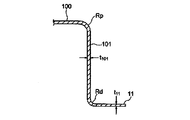
- FIG. 2 is a sectional view taken along line II-II in FIG.
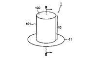
- FIG. 1 is a perspective view showing a molding material 1 manufactured by the molding material manufacturing method according to Embodiment 1 of the present invention.
- the molding material 1 manufactured by the molding material manufacturing method of the present embodiment has a body portion 10 and a flange portion 11.
- the trunk portion 10 is a cylindrical portion having a top wall 100 and a peripheral wall 101 extending from the outer edge of the top wall 100.
- the top wall 100 may be referred to as another method such as a bottom wall.
- the trunk portion 10 is shown to have a true circular cross section, but the trunk portion 10 may have another shape such as an elliptical cross section or a rectangular tube.
- the top wall 100 can be further processed, for example, by forming a protrusion further protruding from the top wall 100.
- the flange portion 11 is a plate portion formed at an end portion of the trunk portion 10 (an end portion of the peripheral wall 101).
- FIG. 2 is a sectional view taken along line II-II in FIG.
- the plate thickness t ⁇ b> 11 of the flange portion 11 is made thinner than the plate thickness t ⁇ b> 101 of the peripheral wall 101 of the trunk portion 10. As described in detail below, this is caused by the ironing process performed on the region corresponding to the flange portion 11 of the material metal plate 2 (see FIG. 3).
- the plate thickness t11 of the flange portion 11 is the average value of the plate thickness of the flange portion 11 between the lower end of the lower shoulder Rd between the peripheral wall 101 and the flange portion 11 and the outer end of the flange portion 11. means.
- the plate thickness t101 of the peripheral wall 101 means the average value of the plate thickness of the peripheral wall 101 between the upper end of the lower shoulder Rd and the lower end of the upper shoulder Rp.
- FIG. 3 is an explanatory view showing a molding material manufacturing method for manufacturing the molding material 1 of FIG.
- the molding material manufacturing method of this invention manufactures the molding material 1 by performing the shaping
- FIG. The at least two forming processes include at least one drawing process and at least one drawing process performed after the drawing process.
- the molding material 1 is manufactured by one drawing process and four redraw processes (first to fourth drawing processes).
- FIG. 4 is an explanatory view showing the mold 3 used for the drawing-out process of FIG. 3
- FIG. 5 is an explanatory view showing the drawing-out process by the mold 3 of FIG.
- the die 3 used for drawing-out processing includes a die 30, a punch 31, and a cushion pad 32.
- the die 30 is provided with a pressing hole 30 a into which the material metal plate 2 is pressed together with the punch 31.
- the cushion pad 32 is disposed at the outer peripheral position of the punch 31 so as to face the outer end surface of the die 30. As shown in FIG.
- the outer edge portion of the material metal plate 2 is not completely restrained by the die 30 and the cushion pad 32, and the outer edge portion of the material metal plate 2 is restrained by the die 30 and the cushion pad 32. Squeeze out to the point where it comes off. The entire material metal plate 2 may be pressed out together with the punch 31 into the pressing hole 30a.
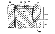
- FIG. 6 is an explanatory view showing the punch 31 of FIG. 4 in more detail.
- the width w 311 of the rear end side 311 of the punch 31 used for drawing-out processing is made wider than the width w 310 of the front end side 310 of the punch 31.
- the width of the pressing hole 30a is substantially uniform along the insertion direction of the punch 31 with respect to the pressing hole 30a. In other words, the inner wall of the die 30 extends substantially parallel to the insertion direction of the punch 31.
- the clearance C 30-31 between the die 30 and the punch 31 in a state where the punch 31 is pushed into the pushing hole 30 a is the rear end of the punch 31 compared to the front end side 310 of the punch 31. Narrow on the side 311.
- Clearance C 30-31 at the rear end 311 of the punch 31, the diaphragm omission processing is set smaller than the previous thickness of the material metal sheet 2 to be performed.
- a width changing portion 31a formed of an inclined surface in which the width of the punch 31 continuously changes is provided between the front end side 310 and the rear end side 311 of the punch 31, a width changing portion 31a formed of an inclined surface in which the width of the punch 31 continuously changes.
- the width changing portion 31a is formed on the lower shoulder of the material metal plate 2 between the width changing portion 31a and the inner wall of the die 30 when the material metal plate 2 is pushed together with the punch 31 in the drawing hole 30a. It arrange
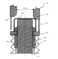
- FIG. 7 is an explanatory view showing the mold 4 used for the first drawing process of FIG. 3
- FIG. 8 is an explanatory view showing the first drawing process by the mold 4 of FIG. 7 and 8, the movement of the mold and the state of processing in the first drawing process will be described in detail.
- the mold 4 used for the first drawing includes a die 40, a punch 41, a drawing sleeve 42, a lifter plate 43, a killer pin 44, and a stopper 45.
- the die 40 is provided with a pressing hole 40a into which the first intermediate body 20 formed by the above-described drawing-out process is pressed together with the punch 41.
- the aperture sleeve 42 is disposed at the outer peripheral position of the punch 41 so as to face the outer end surface 40 b of the die 40.
- FIG. 7 shows a state in which the first intermediate body 20 is placed on the upper surface of the lifter plate 43 and the inner peripheral surface of the first intermediate body 20 is in contact with the outer peripheral surface 42 a of the throttle sleeve 42. .
- the die 40 starts to descend, but since the outer end surface 40b of the die 40 is not in contact with the first intermediate body 20, the drawing of the first intermediate body 20 has not started. Further, the tip of the killer pin 44 provided on the outer end surface 40 b of the die 40 does not reach the upper surface of the lifter plate 43.
- the right half of FIG. 7 shows a state in which the die 40 is further lowered to come into contact with the first intermediate body 20 and drawing is started. At this time, since the tip of the killer pin 44 reaches the upper surface of the lifter plate 43, the die 40 is lowered and the killer pin 44 pushes down the lifter plate 43. As a result, the state where the lower end of the body portion of the first intermediate body 20 does not contact the upper surface of the lifter plate 43 is maintained. That is, the killer pin 44 is longer than the height of the peripheral wall of the first intermediate body 20.
- the die 40 continues to descend further, and the first intermediate body 20 is pushed into the pushing hole 40 a of the die 40, that is, the body of the first intermediate body 20 is drawn. It shows the state being done. Also at this time, the tip of the killer pin 44 reaches the upper surface of the lifter plate 43, and the killer pin 44 pushes down the lifter plate 43 as the die 40 descends. The lower end of the part is not in contact with the upper surface of the lifter plate 43 and is in a floating state. Since the lower end of the trunk portion is in a state of floating from the upper surface of the lifter plate 43, no upward compressive stress is applied to the circumferential wall of the trunk portion.
- the die 40 and the throttle sleeve 42 are open, and the lower portion of the first intermediate body 20 (the region corresponding to the flange portion 11 in FIG. 2) is not sandwiched between the die 40 and the throttle sleeve 42. .
- FIG. 8 shows a state where the lower surface of the lifter plate 43 comes into contact with the stopper 45 provided on the outer peripheral surface 42a of the throttle sleeve 42 as a result of further lowering of the die 40.
- the throttle sleeve 42 descends in synchronization with the die 40. Thereby, the mold gap between the die 40 and the throttle sleeve 42 is constant.
- the lower portion of the body portion of the first intermediate body 20 is located above the outer peripheral surface 42a of the throttle sleeve 42. For this reason, with the progress of the drawing process of the body portion of the first intermediate body 20, the radius of the lower end of the body portion of the first intermediate body 20 gradually decreases, and the plate thickness of the lower portion of the body portion begins to gradually increase.
- the die gap between the die 40 and the drawing sleeve 42 after the lower surface of the lifter plate 43 comes into contact with the stopper 45 is larger than the plate thickness of the lower portion of the body portion of the first intermediate body 20 that has become thick due to the progress of drawing processing. It is set narrowly. By setting the mold gap in this way, ironing can be performed on the lower portion of the body portion of the first intermediate body 20.
- the mold gap between the die 40 and the drawing sleeve 42 when performing the ironing process is 1... Of the average plate thickness of the lower portion of the body portion of the first intermediate body 20 before the first drawing process. It is preferable that it is 0 times or more and 1.35 times or less.
- the second and third drawing processes in FIG. 3 can be performed using a known mold.
- the drawing process is further performed on a region corresponding to the body portion 10 of the second intermediate body 21 (see FIG. 3) formed by the first drawing process.
- the third drawing process corresponds to a re-striking process, and ironing is performed on an area corresponding to the body portion 10 of the third intermediate 22 (see FIG. 3) formed by the second drawing process.
- a region corresponding to the flange portion 11 in FIG. 2 is shrunk, and a thickening occurs in that region.
- the plate thickness t 11 of the flange portion 11 in the final molded material 1 is set to the peripheral wall 101 of the barrel portion 10. it can be made thinner than the thickness t 101.
- the amount of reduction in the plate thickness in the region corresponding to the flange portion 11 in the drawing-out process can be adjusted as appropriate by changing the clearance C 30-31 on the rear end side 311 of the punch 31 of the die 3 used in the drawing-out process.
- the inventors prepared a circular plate having a thickness of 1.8 mm and a diameter of 116 mm obtained by plating a cold-rolled steel plate of ordinary steel with a Zn—Al—Mg alloy plating as the material metal plate 2.
- drawing-out processing was performed under the following processing conditions.
- Zn-Al-Mg alloy plating is applied to both surfaces of the cold-rolled steel sheet, coating weight of the plating used was a per side 90 g / m 2.
- the shape of the width changing portion 31a an inclined surface or a right-angle step.
- the position of the width changing portion 31a a region corresponding to the lower shoulder portion Rd, a region corresponding to the flange portion 11, or a region corresponding to the trunk portion 10.
- the ironing rate of the region corresponding to the flange portion 11 in the drawing-out process is preferably 50% or less, and more preferably 30% or less.
- galling is not a big problem because it can be improved by applying a ceramic coating or the like to the die or punch.
- ⁇ Raging rate> The definition of the ironing rate is as shown in the following formula (Equation 1).
- the value of the thickness of the material metal plate can be used as the thickness before the ironing process.
- the width changing portion 31a is preferable to provide so as to be in contact with the region corresponding to the lower shoulder portion Rd. Note that the position of the width changing portion 31a is calculated from the position corresponding to the lower shoulder portion Rd after forming the molding material that has been redrawn in advance after the mold conditions at the time of mass production are determined. And decide.
- the lower end of the body portion of the first intermediate body is hereinafter referred to as a flange.
- Table 1 shows the relationship between the average flange thickness before drawing and the flange diameter before and after drawing, which affect the occurrence of wrinkles and buckling when no drawing sleeve is used.
- t 0 is the plate thickness of the material metal plate
- t 1 is the average plate thickness of the flange portion before drawing, that is, the average plate thickness of the corresponding region of the flange portion after drawing-out processing.
- D (n-1) is the flange diameter after the n-1th drawing
- Dn is the flange diameter after the nth drawing.
- Wrinkles buckling occurs is a t 1 ⁇ t 0, Dn ⁇ 0.93 ⁇ D (n-1) is a condition, i.e., the average thickness t 1 of the flange portion of the front drawing is material metal It is thinner than the plate thickness t 0 (t 1 ⁇ t 0 ), and the flange diameter Dn after the n-th drawing is much smaller than the flange diameter D (n-1) after the n-1 drawing.
- the condition was (Dn ⁇ 0.93 ⁇ D (n-1) ).
- Table 2 shows the results when using a throttle sleeve.
- the gap between the die 40 and the drawing sleeve 42 is opened at this time so that the outer edge portion is not sandwiched.
- the thickness reduction of the peripheral wall was suppressed.
- the ironing process is performed on the area where the plate thickness is reduced by performing the ironing process in the drawing-out process, the flange diameter is reduced.
- the die 40, the drawing sleeve 42, The mold gap (clearance) was set to be constant at various values.
- the mold gap was made constant at the timing at which shrinkage processing started for the region where the plate thickness was reduced by ironing.
- the flange diameter after the nth drawing was significantly smaller than the flange diameter after the (n-1) drawing (Dn ⁇ 0.93 ⁇ D (n-1) ).
- the n-th stop flange diameter D (n-1) than the significantly smaller condition flange diameter Dn after processing after the n-1 drawing set mold gaps (clearances) to various values As shown in Table 2, when the drawing clearance was 1.0 times or more and 1.35 times or less the average flange thickness before drawing, There was no bending.
- FIG. 9 is a graph showing the plate thickness distribution of the molding material produced from the first intermediate.
- FIG. 10 is an explanatory diagram showing the plate thickness measurement position in FIG. Prior to the drawing process, the drawing-out process for performing the ironing process is performed, so that the plate thickness of the flange portion 11 in the final formed material is larger than the plate thickness (1.8 mm) of the material metal plate, and the peripheral wall of the body portion It was possible to make it thinner than the plate thickness (around 1.6 mm). Further, when the outer dimensions of both of the molding materials are the same, the molding material (invention) subjected to drawing-out processing that performs ironing prior to drawing processing is 10 times more than the molding material obtained by the conventional ordinary drawing method. % Was lighter.
- the drawing-out process accompanied with ironing is performed, a region corresponding to the flange portion 11 of the material metal plate 2 is stretched.
- the amount corresponding to the area corresponding to the flange portion 11 is reduced in advance.
- a material metal plate may be used, or an unnecessary portion of the flange portion 11 may be trimmed.
- the material metal plate 2 is pushed into the pushing hole 30a together with the punch 31 in the drawing-out process, so that the region corresponding to the flange portion 11 of the material metal plate 2 is applied.
- the ironing process is performed, and in the subsequent drawing process, the portion whose thickness is reduced by the ironing process is formed while being sandwiched between the die 40 and the drawing sleeve 42, so that wrinkles and buckling are prevented and the thickness of the flange part is reduced. Can be prevented from becoming thicker than necessary, and the weight of the molding material can be reduced.
- This configuration is particularly useful in applications where a reduction in the weight of a molding material such as a motor case or a reduction in the size of a metal sheet is required.
- the ironing rate of the ironing process in the drawing-out process is 50% or less, the occurrence of seizing and cracking can be avoided.
- the width changing portion 31a formed of an inclined surface in which the width of the punch 31 continuously changes is provided between the front end side 310 and the rear end side 311 of the punch 31, the width changing portion 31a in the ironing process It is possible to avoid the occurrence of plating defects due to the contact.
- the width change part 31a is arrange
- the gap between the die 40 and the drawing sleeve 42 is opened so as not to sandwich the material, so that the peripheral wall of the body Suppresses the decrease in plate thickness.
- the drawing process is performed on the region where the plate thickness is reduced due to the ironing process in the drawing-out process, the mold gap between the die 40 and the drawing sleeve 42 is kept constant to form the flange. It is possible to avoid the occurrence of wrinkles and buckling in the region corresponding to the part.
- the drawing process is described as being performed three times, but the number of drawing processes may be appropriately changed according to the size of the molding material and the required dimensional accuracy.
Landscapes
- Engineering & Computer Science (AREA)
- Mechanical Engineering (AREA)
- Shaping Metal By Deep-Drawing, Or The Like (AREA)
- Forging (AREA)
Priority Applications (7)
| Application Number | Priority Date | Filing Date | Title |
|---|---|---|---|
| KR1020187027348A KR101935759B1 (ko) | 2016-02-23 | 2017-02-21 | 성형재 제조 방법 및 그 성형재 |
| EP17756457.2A EP3401033B1 (de) | 2016-02-23 | 2017-02-21 | Formmaterialherstellungsverfahren und formmaterial |
| PL17756457T PL3401033T3 (pl) | 2016-02-23 | 2017-02-21 | Sposób wytwarzania uformowanego materiału i uformowany materiał |
| CN201780012929.8A CN108778551B (zh) | 2016-02-23 | 2017-02-21 | 成形件制造方法 |
| MX2018010129A MX2018010129A (es) | 2016-02-23 | 2017-02-21 | Metodo de produccion de material moldeado y material moldeado. |
| JP2017524059A JP6305648B2 (ja) | 2016-02-23 | 2017-02-21 | 成形材製造方法 |
| US16/078,181 US10500626B2 (en) | 2016-02-23 | 2017-02-21 | Molded material production method and molded material |
Applications Claiming Priority (2)
| Application Number | Priority Date | Filing Date | Title |
|---|---|---|---|
| JP2016-032443 | 2016-02-23 | ||
| JP2016032443 | 2016-02-23 |
Publications (1)
| Publication Number | Publication Date |
|---|---|
| WO2017146019A1 true WO2017146019A1 (ja) | 2017-08-31 |
Family
ID=59686214
Family Applications (1)
| Application Number | Title | Priority Date | Filing Date |
|---|---|---|---|
| PCT/JP2017/006292 Ceased WO2017146019A1 (ja) | 2016-02-23 | 2017-02-21 | 成形材製造方法及びその成形材 |
Country Status (10)
| Country | Link |
|---|---|
| US (1) | US10500626B2 (de) |
| EP (1) | EP3401033B1 (de) |
| JP (1) | JP6305648B2 (de) |
| KR (1) | KR101935759B1 (de) |
| CN (1) | CN108778551B (de) |
| MX (1) | MX2018010129A (de) |
| MY (1) | MY170562A (de) |
| PL (1) | PL3401033T3 (de) |
| TW (1) | TWI711499B (de) |
| WO (1) | WO2017146019A1 (de) |
Families Citing this family (5)
| Publication number | Priority date | Publication date | Assignee | Title |
|---|---|---|---|---|
| US10500626B2 (en) | 2016-02-23 | 2019-12-10 | Nippon Steel Nisshin Co., Ltd. | Molded material production method and molded material |
| CN108883456B (zh) * | 2016-02-24 | 2019-09-24 | 日新制钢株式会社 | 成形件制造方法 |
| EP3750647B1 (de) * | 2019-06-14 | 2021-10-13 | Saeta GmbH & Co. KG | Verfahren zur herstellung einer tiefziehverschlusskappe |
| CN110722045B (zh) * | 2019-10-28 | 2021-04-02 | 安徽工业大学 | 一种深筒件高减薄率拉深工艺 |
| CN112845786A (zh) * | 2020-12-30 | 2021-05-28 | 大连神通模具有限公司 | 板材冷冲压拉深增材制造新工艺 |
Citations (3)
| Publication number | Priority date | Publication date | Assignee | Title |
|---|---|---|---|---|
| JP2013051765A (ja) * | 2011-08-30 | 2013-03-14 | Minebea Motor Manufacturing Corp | Dcモータ |
| WO2014109263A1 (ja) * | 2013-01-09 | 2014-07-17 | 新日鐵住金株式会社 | プレス成形方法 |
| JP2016002552A (ja) * | 2014-06-13 | 2016-01-12 | 日新製鋼株式会社 | 成形材製造方法及びその成形材 |
Family Cites Families (14)
| Publication number | Priority date | Publication date | Assignee | Title |
|---|---|---|---|---|
| JPS57159224A (en) * | 1981-03-27 | 1982-10-01 | Mitsubishi Electric Corp | Plastic working method for metal |
| JPS635648A (ja) | 1986-06-25 | 1988-01-11 | Matsushita Electric Ind Co Ltd | 回線終端装置 |
| US20080299352A1 (en) * | 2007-05-31 | 2008-12-04 | Nissan Motor Co., Ltd. | Press-molded product and method of manufacturing same |
| JP5039720B2 (ja) * | 2009-01-28 | 2012-10-03 | ジヤトコ株式会社 | ワークの成形方法及び成形システム |
| JP5262872B2 (ja) * | 2009-03-13 | 2013-08-14 | アイシン・エィ・ダブリュ株式会社 | 段付カップ状部品の成形装置及び成形方法 |
| CN201664722U (zh) * | 2009-11-27 | 2010-12-08 | 马鞍山市辰兴机械制造有限公司 | 高精度冲压模具 |
| JP6001883B2 (ja) * | 2012-03-09 | 2016-10-05 | 株式会社神戸製鋼所 | プレス成形品の製造方法およびプレス成形品 |
| US9573183B2 (en) * | 2012-05-18 | 2017-02-21 | Stolle Machinery Company, Llc | Container, and selectively formed shell, and tooling and associated method for providing same |
| MX355006B (es) * | 2012-12-19 | 2018-03-28 | Nippon Steel & Sumitomo Metal Corp | Molde para estampado y método para fabricar productos estampados. |
| KR101644765B1 (ko) * | 2013-01-09 | 2016-08-01 | 신닛테츠스미킨 카부시키카이샤 | 프레스 성형 방법 |
| WO2014109240A1 (ja) * | 2013-01-09 | 2014-07-17 | 新日鐵住金株式会社 | プレス成形方法 |
| JP5892150B2 (ja) * | 2013-12-09 | 2016-03-23 | ダイキン工業株式会社 | 熱交換器用フィンのアイアニング加工装置、熱交換器用フィン製造方法及び熱交換器製造方法 |
| JP5697787B1 (ja) * | 2014-05-19 | 2015-04-08 | 日新製鋼株式会社 | 成形材製造方法 |
| US10500626B2 (en) | 2016-02-23 | 2019-12-10 | Nippon Steel Nisshin Co., Ltd. | Molded material production method and molded material |
-
2017
- 2017-02-21 US US16/078,181 patent/US10500626B2/en active Active
- 2017-02-21 MY MYPI2018702757A patent/MY170562A/en unknown
- 2017-02-21 PL PL17756457T patent/PL3401033T3/pl unknown
- 2017-02-21 MX MX2018010129A patent/MX2018010129A/es unknown
- 2017-02-21 EP EP17756457.2A patent/EP3401033B1/de active Active
- 2017-02-21 CN CN201780012929.8A patent/CN108778551B/zh active Active
- 2017-02-21 WO PCT/JP2017/006292 patent/WO2017146019A1/ja not_active Ceased
- 2017-02-21 KR KR1020187027348A patent/KR101935759B1/ko active Active
- 2017-02-21 JP JP2017524059A patent/JP6305648B2/ja active Active
- 2017-02-22 TW TW106105936A patent/TWI711499B/zh active
Patent Citations (3)
| Publication number | Priority date | Publication date | Assignee | Title |
|---|---|---|---|---|
| JP2013051765A (ja) * | 2011-08-30 | 2013-03-14 | Minebea Motor Manufacturing Corp | Dcモータ |
| WO2014109263A1 (ja) * | 2013-01-09 | 2014-07-17 | 新日鐵住金株式会社 | プレス成形方法 |
| JP2016002552A (ja) * | 2014-06-13 | 2016-01-12 | 日新製鋼株式会社 | 成形材製造方法及びその成形材 |
Also Published As
| Publication number | Publication date |
|---|---|
| JP6305648B2 (ja) | 2018-04-04 |
| JPWO2017146019A1 (ja) | 2018-03-08 |
| US10500626B2 (en) | 2019-12-10 |
| TW201739533A (zh) | 2017-11-16 |
| KR101935759B1 (ko) | 2019-01-04 |
| PL3401033T3 (pl) | 2021-01-25 |
| KR20180112057A (ko) | 2018-10-11 |
| CN108778551B (zh) | 2020-05-12 |
| EP3401033A4 (de) | 2019-01-23 |
| TWI711499B (zh) | 2020-12-01 |
| MY170562A (en) | 2019-08-19 |
| US20190047034A1 (en) | 2019-02-14 |
| EP3401033B1 (de) | 2020-04-22 |
| EP3401033A1 (de) | 2018-11-14 |
| CN108778551A (zh) | 2018-11-09 |
| MX2018010129A (es) | 2019-01-21 |
Similar Documents
| Publication | Publication Date | Title |
|---|---|---|
| JP6305648B2 (ja) | 成形材製造方法 | |
| JP6305649B2 (ja) | 成形材製造方法 | |
| JP6352539B2 (ja) | 成形材製造方法 | |
| PH12015501690B1 (en) | Formed material manufacturing method | |
| WO2017145856A1 (ja) | 成形材製造方法及びその成形材 | |
| AU2015272926B2 (en) | Molded material production method and molded material | |
| AU2014382226B2 (en) | Formed material manufacturing method and formed material | |
| EA031219B1 (ru) | Пресс-форма для вытяжки с утонением и способ изготовления формованного материала |
Legal Events
| Date | Code | Title | Description |
|---|---|---|---|
| ENP | Entry into the national phase |
Ref document number: 2017524059 Country of ref document: JP Kind code of ref document: A |
|
| WWE | Wipo information: entry into national phase |
Ref document number: 2017756457 Country of ref document: EP |
|
| ENP | Entry into the national phase |
Ref document number: 2017756457 Country of ref document: EP Effective date: 20180809 |
|
| WWE | Wipo information: entry into national phase |
Ref document number: MX/A/2018/010129 Country of ref document: MX |
|
| NENP | Non-entry into the national phase |
Ref country code: DE |
|
| ENP | Entry into the national phase |
Ref document number: 20187027348 Country of ref document: KR Kind code of ref document: A |