WO2017146045A1 - 成形材製造方法及びその成形材 - Google Patents
成形材製造方法及びその成形材 Download PDFInfo
- Publication number
- WO2017146045A1 WO2017146045A1 PCT/JP2017/006364 JP2017006364W WO2017146045A1 WO 2017146045 A1 WO2017146045 A1 WO 2017146045A1 JP 2017006364 W JP2017006364 W JP 2017006364W WO 2017146045 A1 WO2017146045 A1 WO 2017146045A1
- Authority
- WO
- WIPO (PCT)
- Prior art keywords
- molding material
- die
- sleeve
- plate
- flange portion
- Prior art date
- Legal status (The legal status is an assumption and is not a legal conclusion. Google has not performed a legal analysis and makes no representation as to the accuracy of the status listed.)
- Ceased
Links
Images





Classifications
-
- B—PERFORMING OPERATIONS; TRANSPORTING
- B21—MECHANICAL METAL-WORKING WITHOUT ESSENTIALLY REMOVING MATERIAL; PUNCHING METAL
- B21D—WORKING OR PROCESSING OF SHEET METAL OR METAL TUBES, RODS OR PROFILES WITHOUT ESSENTIALLY REMOVING MATERIAL; PUNCHING METAL
- B21D22/00—Shaping without cutting, by stamping, spinning, or deep-drawing
- B21D22/20—Deep-drawing
- B21D22/28—Deep-drawing of cylindrical articles using consecutive dies
-
- B—PERFORMING OPERATIONS; TRANSPORTING
- B21—MECHANICAL METAL-WORKING WITHOUT ESSENTIALLY REMOVING MATERIAL; PUNCHING METAL
- B21D—WORKING OR PROCESSING OF SHEET METAL OR METAL TUBES, RODS OR PROFILES WITHOUT ESSENTIALLY REMOVING MATERIAL; PUNCHING METAL
- B21D22/00—Shaping without cutting, by stamping, spinning, or deep-drawing
- B21D22/20—Deep-drawing
- B21D22/206—Deep-drawing articles from a strip in several steps, the articles being coherent with the strip during the operation
-
- B—PERFORMING OPERATIONS; TRANSPORTING
- B21—MECHANICAL METAL-WORKING WITHOUT ESSENTIALLY REMOVING MATERIAL; PUNCHING METAL
- B21D—WORKING OR PROCESSING OF SHEET METAL OR METAL TUBES, RODS OR PROFILES WITHOUT ESSENTIALLY REMOVING MATERIAL; PUNCHING METAL
- B21D22/00—Shaping without cutting, by stamping, spinning, or deep-drawing
- B21D22/20—Deep-drawing
- B21D22/21—Deep-drawing without fixing the border of the blank
-
- B—PERFORMING OPERATIONS; TRANSPORTING
- B21—MECHANICAL METAL-WORKING WITHOUT ESSENTIALLY REMOVING MATERIAL; PUNCHING METAL
- B21D—WORKING OR PROCESSING OF SHEET METAL OR METAL TUBES, RODS OR PROFILES WITHOUT ESSENTIALLY REMOVING MATERIAL; PUNCHING METAL
- B21D22/00—Shaping without cutting, by stamping, spinning, or deep-drawing
- B21D22/20—Deep-drawing
- B21D22/22—Deep-drawing with devices for holding the edge of the blanks
-
- B—PERFORMING OPERATIONS; TRANSPORTING
- B21—MECHANICAL METAL-WORKING WITHOUT ESSENTIALLY REMOVING MATERIAL; PUNCHING METAL
- B21D—WORKING OR PROCESSING OF SHEET METAL OR METAL TUBES, RODS OR PROFILES WITHOUT ESSENTIALLY REMOVING MATERIAL; PUNCHING METAL
- B21D24/00—Special deep-drawing arrangements in, or in connection with, presses
- B21D24/02—Die-cushions
Definitions
- the present invention relates to a molding material manufacturing method for manufacturing a molding material having a cylindrical body portion and a flange portion formed at an end portion of the body portion, and the molding material.
- Non-Patent Document 1 by performing drawing processing, a molding material having a cylindrical body portion and a flange portion formed at an end portion of the body portion is manufactured. Has been done.
- the plate thickness of the body portion becomes smaller than the material plate thickness.
- the region corresponding to the flange portion of the material metal plate shrinks as a whole in accordance with the formation of the body portion, the plate thickness of the flange portion is larger than the plate thickness of the material.
- the material may be referred to as “blank”.
- the molding material as described above may be used as a motor case shown in Patent Document 1 below.
- the trunk portion is expected to have a performance as a shield material that prevents magnetic leakage outside the motor case.
- the performance of the stator as a back yoke is also expected from the body.
- the performance as a shield material or a back yoke becomes better as the plate thickness of the body portion increases. For this reason, as described above, when manufacturing a molding material by drawing, a material metal plate that is thicker than the required plate thickness of the barrel is selected in consideration of the reduction in the plate thickness of the barrel by drawing. Is done.
- the flange portion is often used for attaching the motor case to an attachment target. For this reason, it is expected that the flange portion has a certain amount of strength.
- a molding material having a cylindrical body portion and a flange portion formed at the end portion of the body portion is manufactured by drawing, so that the flange portion The plate thickness is larger than the material plate thickness. For this reason, the flange portion may be unnecessarily thick beyond the plate thickness that satisfies the performance expected of the flange portion. This means that the molding material is unnecessarily heavy, and cannot be ignored in applications where a reduction in weight such as a motor case is required.
- drawing using a drawing sleeve may be performed for the purpose of preventing the occurrence of wrinkles and buckling.
- a tensile stress acts on the body portion, resulting in a decrease in the thickness of the body portion peripheral wall.
- the present invention has been made to solve the above-described problems, and its purpose is to avoid unnecessary increase in the thickness of the flange portion, and to reduce the weight of the molding material and the size of the metal plate. It is providing the molding material manufacturing method which can be aimed at, and its molding material.
- the forming material manufacturing method includes a cylindrical body portion and a flange portion formed at an end portion of the body portion by performing at least two forming processes on the metal sheet.
- the at least two molding processes include at least one drawing-out process and at least one drawing process performed after the drawing-out process.
- the blanking process is performed using a die including a die having a pressing hole and a punch, and at least one of the initial drawing processes is performed using a mold including a die and a drawing sleeve, and a molding material.
- the die and the drawing sleeve are opened and the first drawing process is performed.
- the metal between the die and the drawing sleeve is used for the area corresponding to the flange part of the molding material. Ironing with a constant gap between molds A molded material manufacturing method characterized by performing.
- the ironing rate of the ironing process of the molding material manufacturing method according to the present invention may be -35% or more and 50% or less.
- the first drawing process is performed using a mold including a drawing sleeve having a die and a stopper and a lifter plate, and the distance between the mold gaps kept constant is along the axial direction of the drawing sleeve.
- the position of the stopper may be determined.
- the gap between the mold gaps kept constant may be set to the same value as the plate thickness of the flange portion of the molding material.
- a molding material according to the present invention is a molding material manufactured by performing molding processing on a material metal plate at least twice, and has a cylindrical body and a flange formed at an end of the body. And at least two forming processes include at least one drawing-out process and at least one drawing process performed after the drawing-out process. The thickness of the flange portion may be smaller than the thickness of the material metal plate.
- the molding material according to the present invention is a molding material manufactured by performing at least two molding processes on a raw metal plate, and is formed at a cylindrical body portion and an end portion of the body portion. And at least two forming processes include at least one drawing-out process and at least one drawing process performed after the drawing-out process,
- board thickness of the flange part of a molding material may be made smaller than the plate
- the molding material manufacturing method and the molding material of the present invention by controlling the gap of the mold gap between the die and the drawing sleeve, it corresponds to the flange portion of the final molding material in the first drawing process. From the time when the region reaches the closest part of the die and the drawing sleeve, it is equivalent to the flange part of the final molding material by forming with a constant gap of the mold gap between the die and the drawing sleeve Ironing is performed on the area to be processed. Thereby, wrinkles and buckling can be prevented, the plate thickness of the flange portion can be avoided from becoming unnecessarily thick, and the molding material can be reduced in weight. This configuration is particularly useful for various application objects that require a reduction in weight, such as a motor case.
- FIG. 2 is a sectional view taken along line II-II in FIG.
- FIG. 1 is a perspective view showing a molding material 1 manufactured by the molding material manufacturing method according to Embodiment 1 of the present invention.
- the molding material 1 manufactured by the molding material manufacturing method of the present embodiment has a body portion 10 and a flange portion 11.
- the trunk portion 10 is a cylindrical portion having a top wall 100 and a peripheral wall 101 extending from the outer edge of the top wall 100.
- the top wall 100 may be referred to as another method such as a bottom wall.
- the trunk portion 10 is shown to have a true circular cross section, but the trunk portion 10 may have another shape such as an elliptical cross section or a rectangular tube.
- the top wall 100 can be further processed, for example, by forming a protrusion further protruding from the top wall 100.
- the flange portion 11 is a plate portion formed at an end portion of the trunk portion 10 (an end portion of the peripheral wall 101).
- FIG. 2 is a sectional view taken along line II-II in FIG.
- the plate thickness t ⁇ b> 11 of the flange portion 11 is made thinner than the plate thickness t ⁇ b> 101 of the peripheral wall 101 of the trunk portion 10. As described in detail below, this is caused by the ironing process performed on the region corresponding to the flange portion 11 of the material metal plate 2 (see FIG. 3).
- the plate thickness t11 of the flange portion 11 is the average value of the plate thickness of the flange portion 11 between the lower end of the lower shoulder Rd between the peripheral wall 101 and the flange portion 11 and the outer end of the flange portion 11. means.
- the plate thickness t101 of the peripheral wall 101 means the average value of the plate thickness of the peripheral wall 101 between the upper end of the lower shoulder Rd and the lower end of the upper shoulder Rp.
- FIG. 3 is an explanatory view showing a molding material manufacturing method for manufacturing the molding material 1 of FIG.
- the molding material manufacturing method of this invention manufactures the molding material 1 by performing the shaping
- FIG. The at least two forming processes include at least one drawing process and at least one drawing process performed after the drawing process.
- the molding material 1 is manufactured by one drawing process and three drawing processes (first to third drawing processes).
- the material metal plate 2 various metal plates such as a cold-rolled steel plate, a stainless steel plate, and a plated steel plate using these as an original plate can be used.
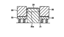
- FIG. 4 is an explanatory view showing the mold 3 used for the drawing-out process of FIG. 3
- FIG. 5 is an explanatory view showing the drawing-out process by the mold 3 of FIG.
- the die 3 used for drawing-out processing includes a die 30, a punch 31, and a cushion pad 32.
- the die 30 is provided with a pressing hole 30 a into which the material metal plate 2 is pressed together with the punch 31.
- the cushion pad 32 is disposed at the outer peripheral position of the punch 31 so as to face the outer end surface of the die 30.
- the outer edge portion of the material metal plate 2 is not completely restrained by the die 30 and the cushion pad 32, and the outer edge portion of the material metal plate 2 is restrained by the die 30 and the cushion pad 32. Squeeze out to the point where it comes off. The entire material metal plate 2 may be pressed out together with the punch 31 into the pressing hole 30a.
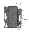
- FIG. 6 is an explanatory view showing the mold 4 used for the first drawing process of FIG. 3
- FIG. 8 is an explanatory view showing the first drawing process by the mold 4 of FIG.
- FIG. 6 and FIG. 7 the movement of the mold and the state of processing in the first drawing will be described in detail.
- the die 4 used for the first drawing includes a die 40, a punch 41, a drawing sleeve 42, a lifter plate 43, a killer pin 44, and a stopper 45.
- the die 40 is provided with a pressing hole 40a into which the first intermediate body 20 formed by the above-described drawing-out process is pressed together with the punch 41.
- the aperture sleeve 42 is disposed at the outer peripheral position of the punch 41 so as to face the outer end surface of the die 40.
- the first intermediate 20 is placed on the upper surface of the lifter plate 43, and the inner peripheral surface of the first intermediate 20 is in contact with the outer peripheral surface of the throttle sleeve 42. Yes.
- the die 40 starts to descend, but since the outer end surface of the die 40 is not in contact with the first intermediate body, the drawing of the first intermediate body 20 has not started.
- the tip of the killer pin 44 provided on the outer end surface of the die 40 does not reach the upper surface of the lifter plate 43.
- the die 40 further descends and comes into contact with the first intermediate body 20, thereby starting drawing.
- the tip of the killer pin 44 reaches the upper surface of the lifter plate 43, the die 40 is lowered and the lifter plate 43 is pushed down.
- the flange tip of the first intermediate body 20 is kept in contact with the upper surface of the lifter plate 43.
- the die 40 continues to descend further, and the drawing process corresponding to the pressing hole 40 a of the die 40 is performed on the body portion of the first intermediate body 20. .
- the tip of the killer pin 44 reaches the upper surface of the lifter plate 43, and pushes down the lifter plate 43 as the die 40 descends. Therefore, the flange tip of the first intermediate body 20 that has undergone drawing is not in contact with the upper surface of the lifter plate 43 and is in a floating state.
- the barrel of the first intermediate body 20 is pushed into the push-in hole 40a by the relative movement of the die 40 and the punch 41, but the upper end of the flange is in a floating state. No compressive stress is applied in the direction.
- the die 40 and the throttle sleeve 42 are open, and the die 40 and the throttle sleeve 42 are not in a state of sandwiching a region corresponding to the outer edge portion of the first intermediate body 20.
- the lower side of the lifter plate 43 comes into contact with a stopper 45 provided on the outer peripheral surface of the throttle sleeve 42 as a result of the die 40 further descending. Since the lower surface of the lifter plate 43 comes into contact with a stopper 45 provided on the outer peripheral surface of the throttle sleeve 42, the throttle sleeve 42 descends in synchronization with the die 40 thereafter. Further, the gap of the mold gap between the die 40 and the throttle sleeve 42 is constant, and at this time, the gap of the mold gap is provided to be the same as the plate thickness of the flange portion 11 of the final molding material 1. Therefore, ironing can be performed in a region corresponding to the flange portion 11 of the final molding material 1.
- the lifter plate 43 contacts the stopper 45 at the timing of starting the ironing process in the region corresponding to the flange portion 11 of the final molding material 1 in the first drawing. Can be determined.
- the gap of the mold gap between the die 40 and the throttle sleeve 42 can be determined by the position of the stopper 45 along the axial direction of the throttle sleeve 42.
- the die 40 and the drawing sleeve 42 sandwich the region corresponding to the flange portion 11 of the final molding material 1 in the first intermediate body 20. At this time, a sufficient ascending pressure must be applied to the throttle sleeve so that the throttle sleeve 42 does not descend until the lifter plate 43 contacts the stopper 45.
- a biasing member 46 such as a spring below the throttle sleeve and adjust its strength.
- the second drawing process and the third drawing process in FIG. 3 can be performed using a known mold.
- the drawing process is further performed on a region corresponding to the body portion 10 of the second intermediate body 21 (see FIG. 3) formed by the first drawing process.
- the third drawing process corresponds to a re-striking process, and ironing is performed on an area corresponding to the body portion 10 of the third intermediate 22 (see FIG. 3) formed by the second drawing process.
- the ironing rate in the first drawing process may be set so as to be equal to or less than the plate thickness of the flange portion 11 of the final molding material 1 in consideration of the increased thickness.
- the ironing rate can be adjusted as appropriate by changing the distance between the mold gaps between the die 40 and the drawing sleeve 42 in the drawing process.
- the plate thickness t 11 of the flange portion 11 is changed to the plate thickness of the peripheral wall 101 of the body portion 10 in the final molded material 1. it can be made thinner than the t 101.
- the inventors prepared a circular plate having a thickness of 1.8 mm and a diameter of 116 mm obtained by applying a Zn—Al—Mg plating to a cold-rolled steel plate of ordinary steel as the material metal plate 2.
- drawing-out processing was performed under the following processing conditions.
- the Zn—Al—Mg alloy plating was applied to both sides of the steel plate, and the amount of plating applied was 90 g / m 2 per side.
- the ironing rate was set by changing the distance of the mold gap between the die 40 and the throttle sleeve 42 by adjusting the position of the stopper 45 attached to the throttle sleeve 42.
- Table 1 shows the relationship between the ironing rate and flange forming evaluation.
- the average plate thickness of the flange of the first intermediate body was 2.0 mm.
- the ironing rate will be -50%.
- the gap between the closest part of the die and the drawing sleeve was large, and the flange portion was wrinkled and buckled.
- the ironing rate was 60%, the crack produced during shaping
- ⁇ Raging rate> The definition of the ironing rate is as shown in the following formula (first formula).
- first formula the value of the flange average plate thickness of the first intermediate can be used as the plate thickness before ironing, and the value of the gap between the mold gaps can be used as the plate thickness after ironing.
- FIG. 8 is a graph showing the plate thickness distribution of the molding material produced from the first intermediate.
- FIG. 9 is explanatory drawing which shows the plate
- the flange portion can be made thinner in the final molded material.
- the weight of the invention example is more than the weight of the comparative example, It was about 10% lighter.
- the first intermediate body 20 is pressed into the pressing hole 40a together with the punch 41 in the drawing process, so that the region corresponding to the flange portion 11 of the first intermediate body 20 is reduced. Ironing is performed. Therefore, wrinkles and buckling can be prevented, the thickness of the flange portion 11 can be prevented from becoming unnecessarily thick, and the weight of the molding material 1 can be reduced.
- This configuration is particularly useful in applications where a reduction in the weight of a molding material such as a motor case or a reduction in the size of a metal sheet is required.
- the ironing rate of ironing in drawing is in the range of -35% to 50%, it is possible to avoid the occurrence of wrinkles, buckling and cracks.
- the drawing process is performed on the region corresponding to the body portion, the reduction in the thickness of the peripheral wall portion is suppressed by opening the space between the die 40 and the drawing sleeve 42 so as not to pinch the material.
- the region corresponding to the flange portion of the intermediate body reaches the closest portion of the die 40 and the drawing sleeve, the flange portion is formed by keeping the mold gap between the die 40 and the drawing sleeve 42 constant. It is possible to avoid the occurrence of wrinkles and buckling in the region corresponding to.
- the drawing process is described as being performed three times, but the number of drawing processes may be appropriately changed according to the size of the molding material and the required dimensional accuracy.
Landscapes
- Engineering & Computer Science (AREA)
- Mechanical Engineering (AREA)
- Shaping Metal By Deep-Drawing, Or The Like (AREA)
- Forging (AREA)
Priority Applications (7)
| Application Number | Priority Date | Filing Date | Title |
|---|---|---|---|
| JP2017524060A JP6305649B2 (ja) | 2016-02-24 | 2017-02-21 | 成形材製造方法 |
| EP17756483.8A EP3401034B1 (de) | 2016-02-24 | 2017-02-21 | Formmaterialherstellungsverfahren und formmaterial |
| MX2018010165A MX372618B (es) | 2016-02-24 | 2017-02-21 | Metodo de produccion de material moldeado y material moldeado |
| PL17756483.8T PL3401034T3 (pl) | 2016-02-24 | 2017-02-21 | Sposób wytwarzania materiału prasowanego i materiał prasowany |
| US16/078,380 US10894283B2 (en) | 2016-02-24 | 2017-02-21 | Molded material production method and molded material |
| CN201780012962.0A CN108883456B (zh) | 2016-02-24 | 2017-02-21 | 成形件制造方法 |
| KR1020187027595A KR101920608B1 (ko) | 2016-02-24 | 2017-02-21 | 성형재 제조 방법 및 그 성형재 |
Applications Claiming Priority (2)
| Application Number | Priority Date | Filing Date | Title |
|---|---|---|---|
| JP2016-033361 | 2016-02-24 | ||
| JP2016033361 | 2016-02-24 |
Publications (1)
| Publication Number | Publication Date |
|---|---|
| WO2017146045A1 true WO2017146045A1 (ja) | 2017-08-31 |
Family
ID=59685253
Family Applications (1)
| Application Number | Title | Priority Date | Filing Date |
|---|---|---|---|
| PCT/JP2017/006364 Ceased WO2017146045A1 (ja) | 2016-02-24 | 2017-02-21 | 成形材製造方法及びその成形材 |
Country Status (10)
| Country | Link |
|---|---|
| US (1) | US10894283B2 (de) |
| EP (1) | EP3401034B1 (de) |
| JP (1) | JP6305649B2 (de) |
| KR (1) | KR101920608B1 (de) |
| CN (1) | CN108883456B (de) |
| MX (1) | MX372618B (de) |
| MY (1) | MY170231A (de) |
| PL (1) | PL3401034T3 (de) |
| TW (1) | TWI694876B (de) |
| WO (1) | WO2017146045A1 (de) |
Cited By (1)
| Publication number | Priority date | Publication date | Assignee | Title |
|---|---|---|---|---|
| CN107824686A (zh) * | 2017-11-04 | 2018-03-23 | 滁州市新康达金属制品有限公司 | 冰箱后背板冲裁翻边模具 |
Families Citing this family (5)
| Publication number | Priority date | Publication date | Assignee | Title |
|---|---|---|---|---|
| CN108883456B (zh) | 2016-02-24 | 2019-09-24 | 日新制钢株式会社 | 成形件制造方法 |
| JP6527544B2 (ja) * | 2017-03-28 | 2019-06-05 | Jfeスチール株式会社 | プレス成形装置及びプレス成形品の製造方法 |
| JP6616027B1 (ja) * | 2019-01-30 | 2019-12-04 | 日鉄日新製鋼株式会社 | 筒状回転部品の製造方法 |
| CN113770244A (zh) * | 2021-09-18 | 2021-12-10 | 二重(德阳)重型装备有限公司 | 一种高放废液玻璃固化容器上封头的制造方法 |
| CN116586497A (zh) * | 2023-07-17 | 2023-08-15 | 协易科技精机(中国)有限公司 | 一种单工位多道次拉深装置 |
Citations (4)
| Publication number | Priority date | Publication date | Assignee | Title |
|---|---|---|---|---|
| JPS57159224A (en) * | 1981-03-27 | 1982-10-01 | Mitsubishi Electric Corp | Plastic working method for metal |
| JP2013051765A (ja) * | 2011-08-30 | 2013-03-14 | Minebea Motor Manufacturing Corp | Dcモータ |
| WO2014109263A1 (ja) * | 2013-01-09 | 2014-07-17 | 新日鐵住金株式会社 | プレス成形方法 |
| JP2016002552A (ja) * | 2014-06-13 | 2016-01-12 | 日新製鋼株式会社 | 成形材製造方法及びその成形材 |
Family Cites Families (11)
| Publication number | Priority date | Publication date | Assignee | Title |
|---|---|---|---|---|
| JPS5981428A (ja) | 1982-10-27 | 1984-05-11 | Kenzo Asai | 調理用油の飛散防止壁体 |
| DE3437123A1 (de) * | 1984-10-10 | 1986-04-10 | Edmund Dipl.-Ing. 6100 Darmstadt Böhm | Verfahren und umformwerkzeug zum gleichlauf-weiterziehen von napffoermigen werkstuecken |
| US4584859A (en) * | 1985-08-23 | 1986-04-29 | Weirton Steel Corporation | In-line control during draw-redraw of one-piece sheet metal can bodies |
| JPH07106394B2 (ja) * | 1989-05-17 | 1995-11-15 | 東洋製罐株式会社 | 絞りしごき缶の製造方法 |
| SE9301097D0 (sv) * | 1993-03-31 | 1993-03-31 | Attexor Equipements Sa | A method for joining together two or several overlaying sheet formed members, an apparatus for carrying out said method and a joint resulting from said method |
| JP4537571B2 (ja) * | 2000-12-28 | 2010-09-01 | 独立行政法人理化学研究所 | 両面同時しごき深絞り加工法 |
| JP2006326671A (ja) * | 2005-05-30 | 2006-12-07 | Asmo Co Ltd | フランジ付き有底筒体の製造方法、フランジ付き有底筒体、及び回転電機のヨーク |
| US20100251798A1 (en) * | 2009-04-06 | 2010-10-07 | The Coca-Cola Company | Method of Manufacturing a Metal Vessel |
| ES2426319B1 (es) * | 2012-04-19 | 2014-09-02 | Expal Systems, S.A. | Proceso y sistema de conformado de una lámina metálica |
| US10500626B2 (en) * | 2016-02-23 | 2019-12-10 | Nippon Steel Nisshin Co., Ltd. | Molded material production method and molded material |
| CN108883456B (zh) | 2016-02-24 | 2019-09-24 | 日新制钢株式会社 | 成形件制造方法 |
-
2017
- 2017-02-21 CN CN201780012962.0A patent/CN108883456B/zh active Active
- 2017-02-21 US US16/078,380 patent/US10894283B2/en active Active
- 2017-02-21 JP JP2017524060A patent/JP6305649B2/ja active Active
- 2017-02-21 MY MYPI2018702758A patent/MY170231A/en unknown
- 2017-02-21 PL PL17756483.8T patent/PL3401034T3/pl unknown
- 2017-02-21 MX MX2018010165A patent/MX372618B/es active IP Right Grant
- 2017-02-21 EP EP17756483.8A patent/EP3401034B1/de active Active
- 2017-02-21 KR KR1020187027595A patent/KR101920608B1/ko active Active
- 2017-02-21 WO PCT/JP2017/006364 patent/WO2017146045A1/ja not_active Ceased
- 2017-02-24 TW TW106106442A patent/TWI694876B/zh active
Patent Citations (4)
| Publication number | Priority date | Publication date | Assignee | Title |
|---|---|---|---|---|
| JPS57159224A (en) * | 1981-03-27 | 1982-10-01 | Mitsubishi Electric Corp | Plastic working method for metal |
| JP2013051765A (ja) * | 2011-08-30 | 2013-03-14 | Minebea Motor Manufacturing Corp | Dcモータ |
| WO2014109263A1 (ja) * | 2013-01-09 | 2014-07-17 | 新日鐵住金株式会社 | プレス成形方法 |
| JP2016002552A (ja) * | 2014-06-13 | 2016-01-12 | 日新製鋼株式会社 | 成形材製造方法及びその成形材 |
Non-Patent Citations (1)
| Title |
|---|
| See also references of EP3401034A4 * |
Cited By (1)
| Publication number | Priority date | Publication date | Assignee | Title |
|---|---|---|---|---|
| CN107824686A (zh) * | 2017-11-04 | 2018-03-23 | 滁州市新康达金属制品有限公司 | 冰箱后背板冲裁翻边模具 |
Also Published As
| Publication number | Publication date |
|---|---|
| TWI694876B (zh) | 2020-06-01 |
| MY170231A (en) | 2019-07-10 |
| CN108883456A (zh) | 2018-11-23 |
| US10894283B2 (en) | 2021-01-19 |
| JP6305649B2 (ja) | 2018-04-04 |
| MX372618B (es) | 2020-05-07 |
| US20190283101A1 (en) | 2019-09-19 |
| KR20180115320A (ko) | 2018-10-22 |
| KR101920608B1 (ko) | 2018-11-20 |
| JPWO2017146045A1 (ja) | 2018-03-01 |
| EP3401034B1 (de) | 2020-04-08 |
| EP3401034A4 (de) | 2019-02-27 |
| CN108883456B (zh) | 2019-09-24 |
| PL3401034T3 (pl) | 2021-02-22 |
| EP3401034A1 (de) | 2018-11-14 |
| MX2018010165A (es) | 2019-01-10 |
| TW201739532A (zh) | 2017-11-16 |
Similar Documents
| Publication | Publication Date | Title |
|---|---|---|
| JP6305649B2 (ja) | 成形材製造方法 | |
| JP6352539B2 (ja) | 成形材製造方法 | |
| US9901970B2 (en) | Formed material manufacturing method | |
| JP6305648B2 (ja) | 成形材製造方法 | |
| AU2015272926B2 (en) | Molded material production method and molded material | |
| KR102320520B1 (ko) | 성형재 제조 방법 | |
| KR101632547B1 (ko) | 성형재 제조 방법 | |
| KR20160113117A (ko) | 아이어닝 가공용 금형 및 성형재 제조 방법 |
Legal Events
| Date | Code | Title | Description |
|---|---|---|---|
| ENP | Entry into the national phase |
Ref document number: 2017524060 Country of ref document: JP Kind code of ref document: A |
|
| WWE | Wipo information: entry into national phase |
Ref document number: 2017756483 Country of ref document: EP |
|
| ENP | Entry into the national phase |
Ref document number: 2017756483 Country of ref document: EP Effective date: 20180809 |
|
| WWE | Wipo information: entry into national phase |
Ref document number: MX/A/2018/010165 Country of ref document: MX |
|
| NENP | Non-entry into the national phase |
Ref country code: DE |
|
| ENP | Entry into the national phase |
Ref document number: 20187027595 Country of ref document: KR Kind code of ref document: A |