WO2017146201A1 - Procédé de production de film mis en forme - Google Patents
Procédé de production de film mis en forme Download PDFInfo
- Publication number
- WO2017146201A1 WO2017146201A1 PCT/JP2017/007050 JP2017007050W WO2017146201A1 WO 2017146201 A1 WO2017146201 A1 WO 2017146201A1 JP 2017007050 W JP2017007050 W JP 2017007050W WO 2017146201 A1 WO2017146201 A1 WO 2017146201A1
- Authority
- WO
- WIPO (PCT)
- Prior art keywords
- thermoplastic resin
- space
- resin film
- film
- bending
- Prior art date
- Legal status (The legal status is an assumption and is not a legal conclusion. Google has not performed a legal analysis and makes no representation as to the accuracy of the status listed.)
- Ceased
Links
Images



Classifications
-
- B—PERFORMING OPERATIONS; TRANSPORTING
- B29—WORKING OF PLASTICS; WORKING OF SUBSTANCES IN A PLASTIC STATE IN GENERAL
- B29C—SHAPING OR JOINING OF PLASTICS; SHAPING OF MATERIAL IN A PLASTIC STATE, NOT OTHERWISE PROVIDED FOR; AFTER-TREATMENT OF THE SHAPED PRODUCTS, e.g. REPAIRING
- B29C51/00—Shaping by thermoforming, i.e. shaping sheets or sheet like preforms after heating, e.g. shaping sheets in matched moulds or by deep-drawing; Apparatus therefor
- B29C51/10—Forming by pressure difference, e.g. vacuum
-
- B—PERFORMING OPERATIONS; TRANSPORTING
- B29—WORKING OF PLASTICS; WORKING OF SUBSTANCES IN A PLASTIC STATE IN GENERAL
- B29C—SHAPING OR JOINING OF PLASTICS; SHAPING OF MATERIAL IN A PLASTIC STATE, NOT OTHERWISE PROVIDED FOR; AFTER-TREATMENT OF THE SHAPED PRODUCTS, e.g. REPAIRING
- B29C35/00—Heating, cooling or curing, e.g. crosslinking or vulcanising; Apparatus therefor
- B29C35/02—Heating or curing, e.g. crosslinking or vulcanizing during moulding, e.g. in a mould
- B29C35/0288—Controlling heating or curing of polymers during moulding, e.g. by measuring temperatures or properties of the polymer and regulating the process
-
- B—PERFORMING OPERATIONS; TRANSPORTING
- B29—WORKING OF PLASTICS; WORKING OF SUBSTANCES IN A PLASTIC STATE IN GENERAL
- B29C—SHAPING OR JOINING OF PLASTICS; SHAPING OF MATERIAL IN A PLASTIC STATE, NOT OTHERWISE PROVIDED FOR; AFTER-TREATMENT OF THE SHAPED PRODUCTS, e.g. REPAIRING
- B29C51/00—Shaping by thermoforming, i.e. shaping sheets or sheet like preforms after heating, e.g. shaping sheets in matched moulds or by deep-drawing; Apparatus therefor
- B29C51/008—Shaping by thermoforming, i.e. shaping sheets or sheet like preforms after heating, e.g. shaping sheets in matched moulds or by deep-drawing; Apparatus therefor without using a mould, e.g. ballooning
-
- B—PERFORMING OPERATIONS; TRANSPORTING
- B29—WORKING OF PLASTICS; WORKING OF SUBSTANCES IN A PLASTIC STATE IN GENERAL
- B29C—SHAPING OR JOINING OF PLASTICS; SHAPING OF MATERIAL IN A PLASTIC STATE, NOT OTHERWISE PROVIDED FOR; AFTER-TREATMENT OF THE SHAPED PRODUCTS, e.g. REPAIRING
- B29C51/00—Shaping by thermoforming, i.e. shaping sheets or sheet like preforms after heating, e.g. shaping sheets in matched moulds or by deep-drawing; Apparatus therefor
- B29C51/04—Combined thermoforming and prestretching, e.g. biaxial stretching
- B29C51/06—Combined thermoforming and prestretching, e.g. biaxial stretching using pressure difference for prestretching
-
- B—PERFORMING OPERATIONS; TRANSPORTING
- B29—WORKING OF PLASTICS; WORKING OF SUBSTANCES IN A PLASTIC STATE IN GENERAL
- B29C—SHAPING OR JOINING OF PLASTICS; SHAPING OF MATERIAL IN A PLASTIC STATE, NOT OTHERWISE PROVIDED FOR; AFTER-TREATMENT OF THE SHAPED PRODUCTS, e.g. REPAIRING
- B29C51/00—Shaping by thermoforming, i.e. shaping sheets or sheet like preforms after heating, e.g. shaping sheets in matched moulds or by deep-drawing; Apparatus therefor
- B29C51/14—Shaping by thermoforming, i.e. shaping sheets or sheet like preforms after heating, e.g. shaping sheets in matched moulds or by deep-drawing; Apparatus therefor using multilayered preforms or sheets
-
- B—PERFORMING OPERATIONS; TRANSPORTING
- B29—WORKING OF PLASTICS; WORKING OF SUBSTANCES IN A PLASTIC STATE IN GENERAL
- B29C—SHAPING OR JOINING OF PLASTICS; SHAPING OF MATERIAL IN A PLASTIC STATE, NOT OTHERWISE PROVIDED FOR; AFTER-TREATMENT OF THE SHAPED PRODUCTS, e.g. REPAIRING
- B29C51/00—Shaping by thermoforming, i.e. shaping sheets or sheet like preforms after heating, e.g. shaping sheets in matched moulds or by deep-drawing; Apparatus therefor
- B29C51/26—Component parts, details or accessories; Auxiliary operations
- B29C51/30—Moulds
- B29C51/36—Moulds specially adapted for vacuum forming, Manufacture thereof
- B29C51/365—Porous moulds
-
- B—PERFORMING OPERATIONS; TRANSPORTING
- B29—WORKING OF PLASTICS; WORKING OF SUBSTANCES IN A PLASTIC STATE IN GENERAL
- B29C—SHAPING OR JOINING OF PLASTICS; SHAPING OF MATERIAL IN A PLASTIC STATE, NOT OTHERWISE PROVIDED FOR; AFTER-TREATMENT OF THE SHAPED PRODUCTS, e.g. REPAIRING
- B29C51/00—Shaping by thermoforming, i.e. shaping sheets or sheet like preforms after heating, e.g. shaping sheets in matched moulds or by deep-drawing; Apparatus therefor
- B29C51/26—Component parts, details or accessories; Auxiliary operations
- B29C51/42—Heating or cooling
-
- B—PERFORMING OPERATIONS; TRANSPORTING
- B29—WORKING OF PLASTICS; WORKING OF SUBSTANCES IN A PLASTIC STATE IN GENERAL
- B29C—SHAPING OR JOINING OF PLASTICS; SHAPING OF MATERIAL IN A PLASTIC STATE, NOT OTHERWISE PROVIDED FOR; AFTER-TREATMENT OF THE SHAPED PRODUCTS, e.g. REPAIRING
- B29C51/00—Shaping by thermoforming, i.e. shaping sheets or sheet like preforms after heating, e.g. shaping sheets in matched moulds or by deep-drawing; Apparatus therefor
- B29C51/26—Component parts, details or accessories; Auxiliary operations
- B29C51/42—Heating or cooling
- B29C51/421—Heating or cooling of preforms, specially adapted for thermoforming
-
- B—PERFORMING OPERATIONS; TRANSPORTING
- B29—WORKING OF PLASTICS; WORKING OF SUBSTANCES IN A PLASTIC STATE IN GENERAL
- B29C—SHAPING OR JOINING OF PLASTICS; SHAPING OF MATERIAL IN A PLASTIC STATE, NOT OTHERWISE PROVIDED FOR; AFTER-TREATMENT OF THE SHAPED PRODUCTS, e.g. REPAIRING
- B29C51/00—Shaping by thermoforming, i.e. shaping sheets or sheet like preforms after heating, e.g. shaping sheets in matched moulds or by deep-drawing; Apparatus therefor
- B29C51/26—Component parts, details or accessories; Auxiliary operations
- B29C51/42—Heating or cooling
- B29C51/421—Heating or cooling of preforms, specially adapted for thermoforming
- B29C51/424—Heating or cooling of preforms, specially adapted for thermoforming using a heated fluid
-
- B—PERFORMING OPERATIONS; TRANSPORTING
- B29—WORKING OF PLASTICS; WORKING OF SUBSTANCES IN A PLASTIC STATE IN GENERAL
- B29C—SHAPING OR JOINING OF PLASTICS; SHAPING OF MATERIAL IN A PLASTIC STATE, NOT OTHERWISE PROVIDED FOR; AFTER-TREATMENT OF THE SHAPED PRODUCTS, e.g. REPAIRING
- B29C51/00—Shaping by thermoforming, i.e. shaping sheets or sheet like preforms after heating, e.g. shaping sheets in matched moulds or by deep-drawing; Apparatus therefor
- B29C51/26—Component parts, details or accessories; Auxiliary operations
- B29C51/42—Heating or cooling
- B29C51/426—Producing specific thermal regimes during thermoforming to obtain particular properties
-
- B—PERFORMING OPERATIONS; TRANSPORTING
- B29—WORKING OF PLASTICS; WORKING OF SUBSTANCES IN A PLASTIC STATE IN GENERAL
- B29C—SHAPING OR JOINING OF PLASTICS; SHAPING OF MATERIAL IN A PLASTIC STATE, NOT OTHERWISE PROVIDED FOR; AFTER-TREATMENT OF THE SHAPED PRODUCTS, e.g. REPAIRING
- B29C51/00—Shaping by thermoforming, i.e. shaping sheets or sheet like preforms after heating, e.g. shaping sheets in matched moulds or by deep-drawing; Apparatus therefor
- B29C51/26—Component parts, details or accessories; Auxiliary operations
- B29C51/46—Measuring, controlling or regulating
-
- B—PERFORMING OPERATIONS; TRANSPORTING
- B29—WORKING OF PLASTICS; WORKING OF SUBSTANCES IN A PLASTIC STATE IN GENERAL
- B29D—PRODUCING PARTICULAR ARTICLES FROM PLASTICS OR FROM SUBSTANCES IN A PLASTIC STATE
- B29D11/00—Producing optical elements, e.g. lenses or prisms
- B29D11/00009—Production of simple or compound lenses
-
- B—PERFORMING OPERATIONS; TRANSPORTING
- B29—WORKING OF PLASTICS; WORKING OF SUBSTANCES IN A PLASTIC STATE IN GENERAL
- B29D—PRODUCING PARTICULAR ARTICLES FROM PLASTICS OR FROM SUBSTANCES IN A PLASTIC STATE
- B29D11/00—Producing optical elements, e.g. lenses or prisms
- B29D11/00634—Production of filters
- B29D11/00644—Production of filters polarizing
-
- B—PERFORMING OPERATIONS; TRANSPORTING
- B29—WORKING OF PLASTICS; WORKING OF SUBSTANCES IN A PLASTIC STATE IN GENERAL
- B29D—PRODUCING PARTICULAR ARTICLES FROM PLASTICS OR FROM SUBSTANCES IN A PLASTIC STATE
- B29D11/00—Producing optical elements, e.g. lenses or prisms
- B29D11/0073—Optical laminates
-
- G—PHYSICS
- G02—OPTICS
- G02B—OPTICAL ELEMENTS, SYSTEMS OR APPARATUS
- G02B5/00—Optical elements other than lenses
- G02B5/30—Polarising elements
- G02B5/3025—Polarisers, i.e. arrangements capable of producing a definite output polarisation state from an unpolarised input state
- G02B5/3033—Polarisers, i.e. arrangements capable of producing a definite output polarisation state from an unpolarised input state in the form of a thin sheet or foil, e.g. Polaroid
-
- G—PHYSICS
- G02—OPTICS
- G02C—SPECTACLES; SUNGLASSES OR GOGGLES INSOFAR AS THEY HAVE THE SAME FEATURES AS SPECTACLES; CONTACT LENSES
- G02C7/00—Optical parts
- G02C7/12—Polarisers
-
- B—PERFORMING OPERATIONS; TRANSPORTING
- B29—WORKING OF PLASTICS; WORKING OF SUBSTANCES IN A PLASTIC STATE IN GENERAL
- B29C—SHAPING OR JOINING OF PLASTICS; SHAPING OF MATERIAL IN A PLASTIC STATE, NOT OTHERWISE PROVIDED FOR; AFTER-TREATMENT OF THE SHAPED PRODUCTS, e.g. REPAIRING
- B29C35/00—Heating, cooling or curing, e.g. crosslinking or vulcanising; Apparatus therefor
- B29C35/02—Heating or curing, e.g. crosslinking or vulcanizing during moulding, e.g. in a mould
- B29C35/08—Heating or curing, e.g. crosslinking or vulcanizing during moulding, e.g. in a mould by wave energy or particle radiation
- B29C35/0805—Heating or curing, e.g. crosslinking or vulcanizing during moulding, e.g. in a mould by wave energy or particle radiation using electromagnetic radiation
- B29C2035/0822—Heating or curing, e.g. crosslinking or vulcanizing during moulding, e.g. in a mould by wave energy or particle radiation using electromagnetic radiation using IR radiation
-
- B—PERFORMING OPERATIONS; TRANSPORTING
- B29—WORKING OF PLASTICS; WORKING OF SUBSTANCES IN A PLASTIC STATE IN GENERAL
- B29C—SHAPING OR JOINING OF PLASTICS; SHAPING OF MATERIAL IN A PLASTIC STATE, NOT OTHERWISE PROVIDED FOR; AFTER-TREATMENT OF THE SHAPED PRODUCTS, e.g. REPAIRING
- B29C2791/00—Shaping characteristics in general
- B29C2791/004—Shaping under special conditions
- B29C2791/006—Using vacuum
-
- B—PERFORMING OPERATIONS; TRANSPORTING
- B29—WORKING OF PLASTICS; WORKING OF SUBSTANCES IN A PLASTIC STATE IN GENERAL
- B29C—SHAPING OR JOINING OF PLASTICS; SHAPING OF MATERIAL IN A PLASTIC STATE, NOT OTHERWISE PROVIDED FOR; AFTER-TREATMENT OF THE SHAPED PRODUCTS, e.g. REPAIRING
- B29C2791/00—Shaping characteristics in general
- B29C2791/004—Shaping under special conditions
- B29C2791/007—Using fluid under pressure
-
- B—PERFORMING OPERATIONS; TRANSPORTING
- B29—WORKING OF PLASTICS; WORKING OF SUBSTANCES IN A PLASTIC STATE IN GENERAL
- B29K—INDEXING SCHEME ASSOCIATED WITH SUBCLASSES B29B, B29C OR B29D, RELATING TO MOULDING MATERIALS OR TO MATERIALS FOR MOULDS, REINFORCEMENTS, FILLERS OR PREFORMED PARTS, e.g. INSERTS
- B29K2023/00—Use of polyalkenes or derivatives thereof as moulding material
-
- B—PERFORMING OPERATIONS; TRANSPORTING
- B29—WORKING OF PLASTICS; WORKING OF SUBSTANCES IN A PLASTIC STATE IN GENERAL
- B29K—INDEXING SCHEME ASSOCIATED WITH SUBCLASSES B29B, B29C OR B29D, RELATING TO MOULDING MATERIALS OR TO MATERIALS FOR MOULDS, REINFORCEMENTS, FILLERS OR PREFORMED PARTS, e.g. INSERTS
- B29K2027/00—Use of polyvinylhalogenides or derivatives thereof as moulding material
- B29K2027/06—PVC, i.e. polyvinylchloride
-
- B—PERFORMING OPERATIONS; TRANSPORTING
- B29—WORKING OF PLASTICS; WORKING OF SUBSTANCES IN A PLASTIC STATE IN GENERAL
- B29K—INDEXING SCHEME ASSOCIATED WITH SUBCLASSES B29B, B29C OR B29D, RELATING TO MOULDING MATERIALS OR TO MATERIALS FOR MOULDS, REINFORCEMENTS, FILLERS OR PREFORMED PARTS, e.g. INSERTS
- B29K2029/00—Use of polyvinylalcohols, polyvinylethers, polyvinylaldehydes, polyvinylketones or polyvinylketals or derivatives thereof as moulding material
- B29K2029/04—PVOH, i.e. polyvinyl alcohol
-
- B—PERFORMING OPERATIONS; TRANSPORTING
- B29—WORKING OF PLASTICS; WORKING OF SUBSTANCES IN A PLASTIC STATE IN GENERAL
- B29K—INDEXING SCHEME ASSOCIATED WITH SUBCLASSES B29B, B29C OR B29D, RELATING TO MOULDING MATERIALS OR TO MATERIALS FOR MOULDS, REINFORCEMENTS, FILLERS OR PREFORMED PARTS, e.g. INSERTS
- B29K2067/00—Use of polyesters or derivatives thereof, as moulding material
-
- B—PERFORMING OPERATIONS; TRANSPORTING
- B29—WORKING OF PLASTICS; WORKING OF SUBSTANCES IN A PLASTIC STATE IN GENERAL
- B29K—INDEXING SCHEME ASSOCIATED WITH SUBCLASSES B29B, B29C OR B29D, RELATING TO MOULDING MATERIALS OR TO MATERIALS FOR MOULDS, REINFORCEMENTS, FILLERS OR PREFORMED PARTS, e.g. INSERTS
- B29K2069/00—Use of PC, i.e. polycarbonates or derivatives thereof, as moulding material
-
- B—PERFORMING OPERATIONS; TRANSPORTING
- B29—WORKING OF PLASTICS; WORKING OF SUBSTANCES IN A PLASTIC STATE IN GENERAL
- B29K—INDEXING SCHEME ASSOCIATED WITH SUBCLASSES B29B, B29C OR B29D, RELATING TO MOULDING MATERIALS OR TO MATERIALS FOR MOULDS, REINFORCEMENTS, FILLERS OR PREFORMED PARTS, e.g. INSERTS
- B29K2077/00—Use of PA, i.e. polyamides, e.g. polyesteramides or derivatives thereof, as moulding material
-
- B—PERFORMING OPERATIONS; TRANSPORTING
- B29—WORKING OF PLASTICS; WORKING OF SUBSTANCES IN A PLASTIC STATE IN GENERAL
- B29K—INDEXING SCHEME ASSOCIATED WITH SUBCLASSES B29B, B29C OR B29D, RELATING TO MOULDING MATERIALS OR TO MATERIALS FOR MOULDS, REINFORCEMENTS, FILLERS OR PREFORMED PARTS, e.g. INSERTS
- B29K2079/00—Use of polymers having nitrogen, with or without oxygen or carbon only, in the main chain, not provided for in groups B29K2061/00 - B29K2077/00, as moulding material
- B29K2079/08—PI, i.e. polyimides or derivatives thereof
-
- B—PERFORMING OPERATIONS; TRANSPORTING
- B29—WORKING OF PLASTICS; WORKING OF SUBSTANCES IN A PLASTIC STATE IN GENERAL
- B29L—INDEXING SCHEME ASSOCIATED WITH SUBCLASS B29C, RELATING TO PARTICULAR ARTICLES
- B29L2011/00—Optical elements, e.g. lenses, prisms
- B29L2011/0016—Lenses
-
- B—PERFORMING OPERATIONS; TRANSPORTING
- B32—LAYERED PRODUCTS
- B32B—LAYERED PRODUCTS, i.e. PRODUCTS BUILT-UP OF STRATA OF FLAT OR NON-FLAT, e.g. CELLULAR OR HONEYCOMB, FORM
- B32B27/00—Layered products comprising a layer of synthetic resin
- B32B27/34—Layered products comprising a layer of synthetic resin comprising polyamides
-
- B—PERFORMING OPERATIONS; TRANSPORTING
- B32—LAYERED PRODUCTS
- B32B—LAYERED PRODUCTS, i.e. PRODUCTS BUILT-UP OF STRATA OF FLAT OR NON-FLAT, e.g. CELLULAR OR HONEYCOMB, FORM
- B32B27/00—Layered products comprising a layer of synthetic resin
- B32B27/36—Layered products comprising a layer of synthetic resin comprising polyesters
Definitions
- the present invention relates to a method for manufacturing a shaped film.
- Plastic plastic lenses can prevent the transmission of reflected light. Therefore, it is used to protect eyes by blocking strong reflected light outdoors such as ski resorts and fishing, and to ensure safety by blocking reflected light from oncoming vehicles when driving a car.
- the plastic polarizing lens is formed by laminating a plastic lens substrate and a polarizing film. An attached film is used as the polarizing film.
- Patent Document 1 discloses a polarizing film manufacturing method in which a gas is introduced into a member surrounding one surface of a film to pressurize the surface, and the other surface of the film is pressed against a heated mold surface. Is disclosed. Furthermore, a plastic product including the obtained polarizing film is disclosed.
- Patent Document 2 discloses a polyimide film molded product in which a polyimide film is formed in close contact with a mold surface using a pressure difference between a space where one surface of a polyimide film is exposed and a space where the other surface is exposed.
- a manufacturing method is disclosed.
- Patent Document 3 discloses a method of thermoforming by pressing a thermoplastic sheet against a mold using a low-pressure air flow.
- Patent Document 4 discloses a method of forming a thermoplastic polyester under a predetermined temperature condition using a mold. Furthermore, a plastic polarizing lens including the obtained polarizing film is disclosed.
- Patent Document 5 discloses a method of forming a wafer in a curved shape by bringing the wafer into contact with a mold having a surface having a predetermined shape. Further, an optical component including the obtained curved wafer is also disclosed.
- Patent Document 6 discloses a pressure forming mold. Furthermore, a method for forming a film or a sheet by using the mold by the pressure of pressurized air is disclosed.
- Patent Document 7 a preheated planar polarizing film is pressed against a convex surface of a lens substrate while pressing with a pad, and the film is adhered to the convex surface of the lens substrate via a pressure-sensitive adhesive layer. Is described (FIG. 2).
- Patent Document 8 latex is spread on a convex surface of a lens substrate by the film, the film is shaped, and the film is formed on the convex surface of the lens substrate via a latex layer formed on the convex surface.
- a method of pasting is described (FIGS. 3A to 3C).
- Patent Documents 1 to 8 have room for improvement in the following points.
- the method of forming a shape by pressing or adhering the film to the surface of the mold as described in Patent Documents 1 to 6 when the foreign material exists on the surface of the mold, the shape of the foreign material is In some cases, a desired surface shape could not be obtained due to transfer. In addition, foreign matter may adhere to the surface of the shaped film and become contaminated. Thus, there was room for improvement in product yield. Furthermore, this method requires that the mold surface be kept clean, the maintenance and management of the mold is complicated, and there is room for improvement in product production efficiency. Also, as in Patent Document 7, there is room for improvement similar to the above in the method of pressing and forming a film using a pad.
- thermoplastic resin film A step of disposing the thermoplastic resin film so as to divide the space into a first space on one surface side of the film and a second space on the other surface side by the thermoplastic resin film; Heating the thermoplastic resin film; Using the pressure difference between the first space and the second space to bend the thermoplastic resin film in the space; Stopping the bending of the thermoplastic resin film in a state where at least the convex curved surface of both surfaces of the film is exposed in the space; Cooling the curved film;
- a method for producing a shaped film comprising: [2]
- the step of bending the thermoplastic resin film includes: The manufacturing of the shaped film according to [1], including a step of pressurizing at least one of the first space and the second space to bend the thermoplastic resin film into a space having a smaller pressure.
- the step of bending the film includes The process for producing a shaped film according to [1], including a step of depressurizing at least one of the first space or the second space and bending the thermoplastic resin film into a space having a lower pressure.
- the step of bending the film includes The method according to [1], including a step of pressurizing one of the first space and the second space and depressurizing the other space to bend the thermoplastic resin film into the depressurized space.
- the step of bending the thermoplastic resin film includes: Including inserting a medium into one of the first space or the second space and pressurizing the one space to curve the thermoplastic resin film into the other space.
- the step of bending the thermoplastic resin film includes: Using a mold disposed in the first space or the second space, and medium supply means for supplying a medium to the surface of the mold facing the thermoplastic resin film, In the first space or the second space, the thermoplastic resin film is pressed with a medium supplied from the medium supply means between the mold and the thermoplastic resin film, and the other space.
- the method for producing a shaped film according to [2] including a step of bending the thermoplastic resin film without contacting the surface of the mold by utilizing a difference with pressure.
- thermoplastic resin film The method for producing a shaped film according to [6], wherein the molding die has a substantially hemispherical convex surface or concave surface on the surface facing the thermoplastic resin film.
- the step of bending the thermoplastic resin film into the other space By inserting the medium heated in the first space or the second space and pressurizing the space, the thermoplastic resin film is placed in the other space at a temperature of 30 ° C. to 300 ° C.
- the method for producing a shaped film according to [5] comprising a step of bending the film.
- the step of bending the thermoplastic resin film includes: The method for producing a shaped film according to [5], including a step of controlling a bending amount of the thermoplastic resin film based on a position of the thermoplastic resin film detected by a position sensor. [11] Before the step of cooling the curved film, The method for producing a shaped film according to any one of [1] to [10], including a step of heating the curved film again. [12] The method for producing a shaped film according to [11], wherein the reheating step is performed at a temperature from a heating temperature in the heating step to a Tm (melting point) of a resin constituting the thermoplastic resin film.
- the step of disposing the thermoplastic resin film includes placing a thermoplastic resin film so as to cover the opening in the first molding member including the first space portion opened in one side, and Including a step of fixing the plastic resin film to the opening end, In the step of bending the thermoplastic resin film, the first space in which one surface of the thermoplastic resin film is exposed and the second space in which the other surface of the thermoplastic resin film is exposed.
- thermoplastic resin film according to [13] wherein at least a back surface of the surface exposed to the first space portion is covered with a second molding member having a second space portion opened in one side. Manufacturing method of the attachment film.
- the thermoplastic resin film and the A first molding member is disposed in the surrounding member;
- the step of bending the thermoplastic resin film includes the step of bending the thermoplastic resin film by reducing the other while maintaining one of the inside of the surrounding member or the first space portion at normal pressure.
- thermoplastic resin film and the A first molding member is disposed in the surrounding member;
- the step of bending the thermoplastic resin film includes the step of bending the thermoplastic resin film by pressurizing the other while maintaining one of the inside of the surrounding member or the first space portion at normal pressure.
- thermoplastic resin film and the A first molding member is disposed in the surrounding member;
- the step of bending the thermoplastic resin film includes a step of bending the thermoplastic resin film by pressurizing one of the inside of the surrounding member or the first space and reducing the other.
- the step of bending the thermoplastic resin film and the step of heating the curved film again are performed as a series of steps in a state where the thermoplastic resin film is placed on the first molding member.
- the go member includes A first heating means for heating the thermoplastic resin film or a second heating means for heating the inside of the surrounding member; Pressurizing means for pressurizing the inside of the surrounding member or the first space portion of the first molding member, or for depressurizing the inside of the surrounding member or the first space portion of the first molding member.
- Pressure reducing means The method for producing a shaped film according to any one of [15] to [18], wherein: [20] The manufacturing of the shaped film according to [19], wherein the pressurizing unit includes a medium introducing unit configured to insert a medium into the surrounding member or the first space of the first molding member. Method. [21] The method for manufacturing a shaped film according to [20], further including third heating means for heating the medium.
- thermoplastic resin film is selected from a polyvinyl alcohol film, a polyester film, a polyamide film, a polyimide film, a polyolefin film, a polyvinyl chloride film, and a polycarbonate film. 22] The method for producing a shaped film according to any one of the above. [24] A method for producing a polarizing film, comprising the step according to any one of [1] to [23].
- thermoplastic resin film so as to divide the space into a first space on one surface side of the film and a second space on the other surface side by the thermoplastic resin film; Heating the thermoplastic resin film; Using the pressure difference between the first space and the second space to bend the thermoplastic resin film in the space; Stopping the bending of the thermoplastic resin film in a state where at least the convex curved surface of both surfaces of the film is exposed in the space; Cooling the curved film to obtain a polarizing film; Laminating a lens substrate on at least one surface of the polarizing film; A method for manufacturing a polarizing lens.
- thermoplastic resin film can be shaped in a non-contact state on a mold or the like, the surface is difficult to be scratched and foreign matter is difficult to adhere.
- a shaped film having a substantially spherical shape having an extremely smooth surface can be obtained by a simple method. That is, according to the manufacturing method of the present invention, the yield of a product such as a shaped film and an optical material using the shaped film is improved. Furthermore, since the maintenance and management of the mold can be simplified, the production efficiency of the product is improved.
- the method for producing the shaped film of the present invention comprises: Arranging the thermoplastic resin film so as to divide the space into a first space on one surface side of the film and a second space on the other surface side by the thermoplastic resin film; Heating the thermoplastic resin film; Using the pressure difference between the first space and the second space to bend the thermoplastic resin film in the space; Stopping the bending of the thermoplastic resin film in a state where at least the convex curved surface of both surfaces of the film is exposed in the space; Cooling the curved film; including.
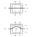
- the manufacturing method of the shaped film of this embodiment includes the following steps.
- Step a The thermoplastic resin film 18 is disposed so as to divide the space into a first space 16 on the one surface 18a side and a second space 22 on the other surface 18b side by the thermoplastic resin film 18 ( FIG. 1 (a)).
- Step b Heat the thermoplastic resin film 18.
- Step c Using the pressure difference between the first space 16 and the second space 22, the thermoplastic resin film 18 is bent into the second space 22 (FIG. 1B).
- Step e Cooling the curved thermoplastic resin film 18.
- each step will be described.
- step a in the first molding member 14 including the first space 16 opened in one side, the thermoplastic resin film 18 is placed so as to cover the opening. One surface 18 a of the thermoplastic resin film 18 is exposed in the first space 16.
- the second molding member 24 including the second space 22 opened on one side is used, and the other side of the second molding member 24 is exposed so that the other surface 18b of the thermoplastic resin film 18 is exposed in the second space 22. The surface 18b is covered.
- the opening end portion of the first molding member 14 and the opening end portion of the second molding member 24 can be fitted, and the thermoplastic resin film 18 can be fixed between these opening end portions.
- the first molding member 14 and the second molding member 24 are made of metal or the like.
- the shape of the first space 16 is not particularly limited as long as the thermoplastic resin film 18 does not contact the inner wall surface of the space 16 of the first molding member 14 and can heat the thermoplastic resin film 18 in the shaping step.
- the shape of the 2nd space 22 will not be specifically limited if the pressure difference between the 1st space 16 and the 2nd space 22 can be utilized in a shaping process, and also the thermoplastic resin film 18 can be heated.
- the first molding member 14 includes a first heating unit that heats the thermoplastic resin film 18, a second heating unit that heats the inside of the first space 16, Transfer means for charging a medium into the first space 16 in order to pressurize the inside of the first space 16; A third heating means for heating the medium or a decompression means for decompressing the inside of the first space 16 may be provided.
- the heated medium may be configured to circulate in the first space 16.
- the first molding member 14 may not be a closed system.
- the second molding member 24 includes a first heating unit that heats the thermoplastic resin film 18, a second heating unit that heats the inside of the second space 22, and a medium to pressurize the inside of the second space 22.
- a transfer means for charging the inside, a third heating means for heating the medium, or a decompression means for decompressing the inside of the second space 22 may be provided.
- the heated medium may be configured to circulate in the second space 22.
- the second molding member 24 may not be a closed system.
- the medium is not particularly limited as long as the thermoplastic resin film 18 can be heated and a pressure difference can be given to the front and back surfaces of the film.
- an inert gas such as air or nitrogen, a liquid such as water vapor or water, etc.
- the first heating means include an infrared irradiation device, a heat ray irradiation device, and an oven.
- An example of the second heating means is an oven.
- thermoplastic resin film 18 examples include polyvinyl alcohol films, polyester films made of polyethylene terephthalate and polyethylene naphthalate, polyamide films, polyimide films, polyolefin films, polyvinyl chloride films, polycarbonate films, and the like. be able to.
- the film thickness of the thermoplastic resin film 18 varies depending on the use of the obtained shaped film, and can be appropriately selected.
- thermoplastic resin films may contain a dichroic dye, a light control pigment, a specific wavelength cut pigment, a dye, an ultraviolet absorber, and the like.
- thermoplastic resin film 18 is heated while being fixed at the opening end of the first molding member 14 and the opening end of the second molding member 24.
- the heating temperature varies depending on the presence / absence of the reheating step described later, the stretched state (presence / absence and magnification) of the thermoplastic resin film 18, the material, and the thickness, in the case of a stretched polyester film, the heating temperature is 30 ° C. to 300 ° C., preferably 100 to 200 ° C., more preferably 120 to 180 ° C.
- the heating temperature of the thermoplastic resin film 18 can be confirmed by measuring the temperature of the medium or the surrounding temperature surrounding the film in the space where the film is exposed.
- thermoplastic resin film 18 In order to heat the thermoplastic resin film 18, a method in which the first heating member provided on the first molding member 14 and / or the second molding member 24 is heated with light, heat rays, etc., the first molding member 14 and / or a method of heating the inside of the first space 16 and / or the inside of the second space 22 by the second heating means provided in the second molding member 24. Furthermore, in step c, the thermoplastic resin film 18 can be heated by using a heated medium. Note that the step b and the step c can be performed simultaneously by a method of circulating the heated medium in the first space 16.
- thermoplastic resin film 18 is bent in the space using the pressure difference between the first space 16 and the second space 22. This step is performed while maintaining the temperature of step b or heating.
- the pressure in the first space 16 at the time of pressurization varies depending on the material of the thermoplastic resin film 18, the temperature, the film thickness, and the desired radius of curvature, but in the case of a stretched polyester film having a thickness of 100 to 200 ⁇ m, it is 0. It is about 001 to 0.4 MPa.
- the pressure difference can be appropriately set based on the material of the thermoplastic resin film 18, the temperature, the film thickness, and the desired radius of curvature.
- the curvature radius of the thermoplastic resin film 18 in the said process is uniquely determined by the relationship between the elastic force of a film, and the applied pressure.
- the curvature of the thermoplastic resin film 18 can be controlled by confirming the deformation amount, pressure, and the like of the curved convex surface or concave surface formed in the thermoplastic resin film 18.
- the step c can include a step of controlling the bending amount of the thermoplastic resin film 18 based on a change in the position of the thermoplastic resin film 18 detected by a position sensor (not shown).
- the position sensor can be provided in the first space 16 or the second space 22.
- the position sensor is configured to detect a change in the position of the thermoplastic resin film 18 with a laser or the like and detect a bending amount.
- the control means can control the bending amount of the thermoplastic resin film 18 by controlling the output of the pressurizing means or the decompression means based on the bending amount.
- the curvature amount of the thermoplastic resin film 18 can be set correctly, and a curve shape can be set arbitrarily.
- the reference position (change amount: 0) of the thermoplastic resin film 18 is, for example, the position of the thermoplastic resin film 18 fixed between the first molding member 14 and the second molding member 24. it can.
- the control means can grasp the change (bending amount) of the thermoplastic resin film 18 based on the position of the thermoplastic resin film 18 read by the position sensor, and can control the output of the pressurizing means or the decompressing means. .
- thermoplastic resin film 18 is stopped in a state where the other surface 18 b of the thermoplastic resin film 18 is exposed in the second space 22. Thereby, the thermoplastic resin film 18 can be shaped without being brought into contact with a mold or the like.
- step d the thermoplastic resin film 18 is bent to a desired shape by the position sensor or control means used in step c, and the thermoplastic resin film is not in contact with the second molding member 24. The 18 curves can be stopped.
- the process (heat setting process) which improves the thermal stability of the curved thermoplastic resin film 18 can be included.
- the temperature at the time of heating again can be the same as or higher than the heating temperature in the step b, and can be preferably the heating temperature in the heating step to the melting point of the resin constituting the thermoplastic resin film. .
- thermoplastic resin film 18 By the reheating step, a dimensional change such as heat shrinkage of the thermoplastic resin film 18 can be reduced.
- thermoplastic resin film 18 when the thermoplastic resin film 18 is made of a material that thermally contracts, if it is contracted to some extent at a temperature equal to or higher than the use temperature, the effect of dimensional stability (the shrinkage at the assumed use temperature can be made smaller). Can be increased).
- this process and the process c which curves the thermoplastic resin film 18 can be performed as a series of processes in a state where the thermoplastic resin film 18 is placed on the first molding member. A film can be obtained.
- the curved thermoplastic resin film 18 obtained in step d is cooled.
- the said process can also be performed with another apparatus, it is preferable to complete
- the cooling include a method of lowering the temperature of the medium, a method of terminating heating by the heating means, and returning to normal temperature.
- a shaped film can be obtained by this embodiment including the above steps.
- the shaped film of this embodiment can be used for various purposes such as a polarizing substrate or polarizing plate or polarizing film for glasses or sunglasses, a specific wavelength cut film, a light control film, a reflective concave mirror, a condensing reflection plate, and the like. it can.
- a plastic polarizing lens will be described as an optical material using the shaped film of the present embodiment as a polarizing element.
- a lens comprising a shaped film (polarizing film) obtained by the above manufacturing method and a plastic lens substrate laminated on at least one surface of the polarizing film.
- polarizing film polarizing film obtained by the above manufacturing method
- plastic lens substrate laminated on at least one surface of the polarizing film.
- it can also be used as a plastic polarizing lens only by the polarizing base material or polarizing plate which consists of a shaped film obtained by said manufacturing method.
- a polarizing film various things, such as an iodine containing polyvinyl alcohol polarizing film, a dichroic dye containing polyvinyl alcohol polarizing film, a dichroic dye containing thermoplastic polyester polarizing film, etc. can be used, for example.
- the polyester-based polarizing film can also contain moisture for the purpose of making it easier to mold than the polyvinyl alcohol polarizing film.
- the thickness of the polarizing film is usually 1 to 500 ⁇ m, preferably 10 to 300 ⁇ m.
- the polarizing film may have a single layer structure, but is a laminate in which sheets made of polycarbonate, triacetyl cellulose, polyamide, acrylic, polyethylene terephthalate, cyclic olefin copolymer, cycloolefin polymer, etc. are laminated on both sides or one side of the polarizing film. It can also be a structure.
- a polarizing substrate or a polarizing plate a laminate structure in which the above sheet is laminated on both surfaces or one side of the polarizing substrate or polarizing plate can also be used.
- the thickness of the polarizing substrate or polarizing plate is usually in the range of 10 to 2000 ⁇ m, preferably 10 to 1000 ⁇ m.
- the polarizing film is treated with a primer (coating), chemical treatment (reactive gas, chemical solution such as acid or alkali), corona discharge treatment, plasma treatment, ultraviolet irradiation treatment. Further, it may be used after one or more pretreatments selected from electron beam irradiation treatment, surface roughening treatment, flame treatment etching treatment, washing treatment and the like are performed. Among such pretreatments, one or more selected from primer coating treatment, chemical treatment, corona discharge treatment, and plasma treatment are particularly preferred.
- the resin constituting the lens substrate include a thermosetting resin or a thermoplastic resin.
- thermosetting resins examples include urethane resins, thiourethane resins, acrylic resins, episulfide resins, and allyl diglycol carbonate resins.
- Thermosetting resins include internal mold release agents, UV absorbers, antioxidants, light stabilizers, oil-soluble dyes, dimming dyes, specific wavelength cut dyes, bluing agents, chain extenders, crosslinking agents, fillers, etc. May be included.
- thermoplastic resin examples include polycarbonate, polyamide, polymethyl methacrylate, polyester, polyolefin, polyurethane, polyether ketone, polyether sulfone, and polyvinyl chloride. You may use as an alloy which mixed these.
- function-imparting agents can be added to these thermoplastic resins.
- the function-imparting agent include an ultraviolet absorber, a heat stabilizer, an antioxidant, a light stabilizer, a flame retardant, a light control dye, a specific wavelength cut dye, a pigment, a dye, a lubricant, a plasticizer, an antistatic agent, and an antifogging agent.
- a phosphorus-based heat stabilizer or a hindered phenol-based antioxidant for the purpose of preventing foreign matters from being generated during melt-kneading in the kneading process or the product manufacturing process.
- a fatty acid ester is suitably used as the mold release agent.
- lower fatty acid esters such as stearic acid monoglycerides and stearic acid stearate, higher fatty acid esters such as sebacic acid behenate, and erythritol esters such as pentaerythritol tetrastearate are used.
- thermoplastic resin film 18 is placed so as to cover the opening portion.
- the thermoplastic resin film 18 is fixed to the opening end by the fixing member 20.
- the thermoplastic resin film 18 is arranged so as to be divided into the first space portion 16 on the one surface 18a side and the space on the other surface 18b side of the thermoplastic resin film 18.
- the inside of the 1st space part 16 is pressurized and the thermoplastic resin film 18 is curved.
- the pressure in the first space portion 16 can be reduced to curve the thermoplastic resin film 18 in the first space portion 16.
- thermoplastic resin film 18 can be directly heated from the other surface 18b side of the thermoplastic resin film 18 when heated by light or infrared rays.
- the step of bending the thermoplastic resin film 18 can be performed by pressurizing the inside of the first space portion 16.
- the method shown in FIG. 2 may be performed in an enclosure member (not shown).
- the surrounding member includes a heating unit that heats the inside of the surrounding member, a pressurizing unit that pressurizes the inside of the surrounding member with gas or water vapor, a heating unit that heats the gas or water vapor, and a pressurizing unit that pressurizes the inside of the first space 16
- a decompression means for decompressing the interior of the first space 16 may be provided.
- the surrounding member may be configured to be open to the atmosphere so that the inside of the surrounding member and the inside of the first space 16 can be maintained at normal pressure.
- the step of bending the thermoplastic resin film 18 can take the following modes. (1) The thermoplastic resin film 18 is bent by pressurizing the inside of the first space portion 16 while maintaining the inside of the surrounding member at normal pressure. (2) The thermoplastic resin film 18 is bent by pressurizing the inside of the surrounding member and the inside of the first space portion 16 and making the pressure in the first space portion 16 larger than the pressure inside the surrounding member. (3) The thermoplastic resin film 18 is bent by depressurizing the inside of the surrounding member and pressurizing the inside of the first space portion 16. (4) The thermoplastic resin film 18 is bent by reducing the pressure inside the surrounding member and the inside of the first space portion 16 so that the pressure inside the first space portion 16 is larger than the pressure inside the surrounding member.
- thermoplastic resin film 18 has been described as being curved in the direction of the other surface 18b. However, by depressurizing the interior of the first space 16, the thermoplastic resin film 18 is curved in the direction of the one surface 18a. It can also be set as an aspect. In addition, when arrange
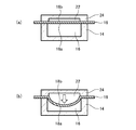
- a shaped film can also be manufactured as shown in FIG. 3, and includes the following steps.
- Step a The thermoplastic resin film 18 is disposed so as to divide the space into a first space 16 on the one surface 18a side and a second space 22 on the other surface 18b side by the thermoplastic resin film 18 ( FIG. 3 (a)).
- Step b Heat the thermoplastic resin film 18.
- Step c Using the pressure difference between the first space 16 and the second space 22, the thermoplastic resin film 18 is bent into the first space 16 without using a mold (FIG. 3B).
- Step d The bending of the thermoplastic resin film 18 is stopped in a state where the one surface 18 a of the thermoplastic resin film 18 is exposed in the first space 16.
- Step e Cooling the curved thermoplastic resin film 18.
- the same configuration as that of the embodiment described in FIG. 1 can be adopted, and the description of the same process is omitted.
- step c in order to generate a pressure difference between the first space 16 and the second space 22, the following modes are exemplified.
- the first molding member 14 is released to the atmosphere, and the medium is charged into the second space 22 while maintaining the inside of the first space 16 at normal pressure.
- the process b and the process c can be performed simultaneously.
- the medium is charged into the first space 16 and the second space 22, and the pressure in the second space 22 is increased.
- the process b and the process c can be performed simultaneously.
- the first molding member 14 having the hemispherical first space 16 as shown in FIG. 4 can be used.
- the shaped film is manufactured by bringing the film 18 into close contact with the first molding member 14 while pressing the film 18 from the second space 22 side. According to this embodiment, the shaped film can be produced without bringing the film 18 into contact with the first molding member 14.
- the step of bending the thermoplastic resin film 18 in the present embodiment can be controlled by, for example, measuring the amount of change according to the volume of the medium used for bending. Further, in the step of bending the thermoplastic resin film 18 in the present embodiment, for example, a liquid (oil or the like) is filled in a space on the side to be bent, and the amount of liquid extruded by the bending of the thermoplastic resin film 18. The end point of the curve can also be controlled with.
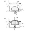
- thermoplastic resin film 18 is arranged by the thermoplastic resin film 18 so as to divide the space into a first space 16 on the one surface 18a side and a second space on the other surface 18b side (FIG. 5 (a)).
- Step b Heat the thermoplastic resin film 18.
- Step c In the first space 16, the thermoplastic resin film 18 and the molding die 32 are not in contact with each other, and the thermoplastic resin film is supplied with the medium 34 supplied between the molding die 32 and the thermoplastic resin film 18. 18 is pressed, and the thermoplastic resin film 18 is bent using the difference from the pressure in the second space (FIG. 5B).
- Step d Stop the bending of the thermoplastic resin film 18.
- the other surface 18b of the thermoplastic resin film 18 is exposed in the second space.
- Step e Cooling the curved thermoplastic resin film 18.
- the same configuration as that of the embodiment described in FIG. 1 can be adopted, and the description of the same process is omitted.
- Step a As shown to Fig.5 (a), in the 1st member 14 for shaping
- a molding die 32 that can move up and down is arranged in the first molding member 14.
- the surface 32a of the mold 32 is a substantially hemispherical convex surface.
- the molding die 32 is a porous body having innumerable pores; a hollow body in which hollow tubes are bundled and solidified so that a medium flows in one direction, for example, a hollow body in which pipe-shaped molded bodies are bundled and solidified; A structure using a plate, for example, a layered laminate in which a plurality of plates are separated and stacked so that a medium flows through the gap; a structure in which a plurality of plates are assembled in a lattice shape or a triangular shape; And the like, and the medium can be supplied to the surface 32 a of the mold 32.
- Sintered metal as a porous body sintered ceramic; aggregate of particulate inorganic materials (ceramic / metal) binder-coated; foamed metal; foamed plastic; Porous rubber; Hollow fiber bundled and hardened; Pipe-like structure made of metal, ceramics, plastic, rubber, etc., bundled and hardened; Plate-like structure made of metal, ceramics, plastic, rubber, etc. And a hollow body laminated with a gap.
- the mold 32 includes a medium supply unit (not shown), and can supply a medium from the inside of the mold 32 to the surface 32a.
- the medium is not particularly limited as long as the thermoplastic resin film 18 can be heated and a pressure difference can be given to the front and back surfaces of the film.
- an inert gas such as air or nitrogen, a liquid such as water vapor or water, etc. Can be mentioned.
- thermoplastic resin film 18 is fixed to the opening end by the fixing member 20
- the mold 32 is moved in the direction of the thermoplastic resin film 18, and the medium 34 is supplied from the medium supply means to the surface 32a of the mold 32. To do. Then, the mold 32 is further raised, and the thermoplastic resin film 18 is bent by the pressing force of the medium 34 (FIG. 5B).
- thermoplastic resin film 18 By supplying the medium 34 to the surface 32a of the mold 32, a layer of the medium 34 is formed between the mold 32 and the thermoplastic resin film 18, and the thermoplastic resin film 18 heated in the step b is molded.
- the surface shape of the mold 32 can be transferred without contacting the mold 32. That is, when the mold 32 is moved toward the thermoplastic film 18 and is gradually pushed into the film 18, the ejection pressure of the medium 34 ejected from the surface of the mold 32 and the elastic modulus at the heating temperature of the film 18. Therefore, the mold 32 and the film 18 are not in contact with each other, and the shape of the mold 32 is not brought into contact with each other. Is transferred to the film 18. As a result, the thermoplastic resin film can be curved. This can be carried out by a method similar to the method of forming a shape by bringing it into contact with a conventional mold, but since the formed film is not in contact with the mold, it is not affected by the surface roughness of the mold.
- thermoplastic resin film 18 has a desired shape.
- the second space on the other surface 18b side of the thermoplastic resin film 18 is open, and atmospheric pressure is applied to the other surface 18b, but as shown in FIG.
- the second molding member 24 having the opened second space 22 is used, and the other surface 18b of the second molding member 24 is formed so that the other surface 18b of the thermoplastic resin film 18 is exposed in the second space 22. It can also be covered. Thereby, the pressure in the second space 22 can also be adjusted.
- a molding die 36 having a substantially hemispherical concave surface can be used as the molding die. 5 and 6, the entire apparatus may be used upside down, or may be used in the horizontal direction. In either case, the thermoplastic resin film can be shaped as described above.
- a glass polarizing lens As an optical material using the shaped film of the present embodiment as a polarizing element, a glass polarizing lens can also be mentioned.
- the glass polarizing lens include those provided with a shaped film (polarizing film) obtained by the above production method and a glass substrate laminated on at least one surface of the polarizing film.
- Example 1 Production of the shaped film shown in FIG. 4
- the first molding member 14 and the second molding member 24 having a laser transmission hole having a diameter of 10 mm in the lower center are heated to 145 degrees (first heating means), and between the members
- a polyethylene terephthalate polarizing film (thickness: 140 ⁇ m) was horizontally stacked and fixed by fitting, and the film distance was set to zero by laser measurement (Keyence Co., Ltd. CCD laser displacement meter LK-G150) and held for 120 seconds.
- the inside of the second space 22 was pressurized with a pressure of 0.04 MPa, and a polyethylene terephthalate polarizing film was expanded to the first space 16 side.
- the pressure in the second space 22 is manually reduced and pressurized by releasing to the atmosphere, and the film distance is set to 30 between -5.6 mm and -5.2 mm. Held for seconds. Further, water is circulated in the first molding member 14, and the film distance is reduced from -5.6 mm to -5.2 mm to 60 while the pressure in the second space 22 is manually reduced and pressurized by releasing to the atmosphere. After the second holding, the first molding member 14 and the second molding member 24 were opened, and a curved film shaped to a height of 5.4 mm and a curvature radius of 130.4 mm was obtained.
- Example 2 Production of the shaped film shown in FIG. 4
- the first molding member 14 and the second molding member 24 having a laser transmission hole having a diameter of 10 mm in the lower center are heated to 145 degrees (first heating means), and between the members
- a polyethylene terephthalate polarizing film (thickness: 140 ⁇ m) was horizontally stacked and fixed by fitting, and the film distance was set to zero by laser measurement (Keyence Co., Ltd. CCD laser displacement meter LK-G150) and held for 120 seconds.
- the inside of the second space 22 was pressurized with a pressure of 0.04 MPa, and a polyethylene terephthalate polarizing film was expanded to the first space 16 side.
- the pressure in the second space 22 is manually reduced and pressurized by releasing to the atmosphere, and the film distance is between -7.5 mm and -6.5 mm. Hold for 30 seconds.
- the pressure in the second space 22 is manually reduced and pressurized by opening to the atmosphere. The distance was held between -5.6 mm and -5.2 mm for 30 seconds.
- water is circulated in the first molding member 14, and the film distance is reduced from -5.6 mm to -5.2 mm to 60 while the pressure in the second space 22 is manually reduced and pressurized by releasing to the atmosphere.
- the first molding member 14 and the second molding member 24 were opened, and a curved film shaped to a height of 5.4 mm and a curvature radius of 130.4 mm was obtained.
- a curved film shaped to a height of 5.4 mm and a curvature radius of 130.4 mm was obtained.
- the surface of the curved film was visually observed, it was confirmed that the surface was free of scratches and foreign matter and had a very smooth surface.
- the cross-sectional shape was observed by cutting the curved film in half, it was confirmed to have a substantially spherical shape.
- Example 3 Production of polarizing lens using shaped film 50.6 parts by weight of m-xylylene diisocyanate, 4,8-dimercaptomethyl-1,11-dimercapto-3,6,9-trithiaundecane and 4,7-di 49.4 parts by weight of a mixture of mercaptomethyl-1,11-dimercapto-3,6,9-trithiaundecane and 5,7-dimercaptomethyl-1,11-dimercapto-3,6,9-trithiaundecane 0.01 part by weight of dibutyltin dichloride as a curing accelerator, 0.1 part by weight of Zelec UN (registered trademark, manufactured by Stepan) as a mold release agent, and Seesorb 709 (manufactured by Sipro Kasei Co., Ltd.) as an ultraviolet absorber 0.05 A part by weight was stirred and dissolved, then defoamed under reduced pressure, and used as a monomer mixture for injection immediately after preparation.
- the viscosity at 20 ° C. after 1 hour of stirring and dissolution was 30 mPa ⁇ s.
- this monomer mixture was injected through a tube after filtration through a 3 ⁇ m filter into two gaps partitioned by two glass molds constituting a lens casting mold and the film formed in Example 1. Note that the separation distance of the narrowest gap was about 0.5 mm.
- the lens casting mold closed is placed in a hot air circulating oven, heated from 25 ° C. to 108 ° C. over 12 hours, then maintained at 108 ° C. for 7 hours, and after slow cooling, the lens is poured from the oven. The mold mold was removed. The lens was released from the lens casting mold and annealed at 110 ° C. for 2.5 hours to obtain a polarized lens.
- Example 4 As a porous material, a porous aluminum material having an average pore diameter of 15 ⁇ m and a porosity of 15% was prepared by cutting out one surface into a concave shape and the back surface into a convex shape with a substantially uniform thickness. This porous material was disposed in the space 16 in the mold of FIG. 3 such that the concave surface faces the film as in the mold 36 of FIG. That is, in FIG. 6, the second molding member 24 of FIG. Air (medium 34) was allowed to flow at a pressure of 0.02 MPa from the back side toward the concave surface of the porous material.
- a PET uniaxially stretched film having a thickness of 140 ⁇ m is fitted between the second molding member 24 and the first molding member 14, and the whole is heated at a temperature of 145 ° C. and held for 120 seconds, and then into the second space 22. After applying 0.06 MPa of air and 60 seconds passed, the second molding member 24 and the first molding member 14 were cooled to 80 degrees. Then, the pressurization in the 1st space 16 and the 2nd space 22 was stopped, the fitting was released, and the bent film was taken out. When the surface of the obtained bent film was visually observed, it was confirmed that the surface was free of scratches and foreign matter and had a very smooth surface. In addition, a lens could be produced in the same manner as in Example 3.
- the present invention can also take the following aspects.
- the step of bending the thermoplastic resin film includes: The method for producing a shaped film according to [1], including a step of pressurizing one of the first space and the second space to curve the thermoplastic resin film into the other space.
- the step of bending the film includes The method for producing a shaped film according to [1], including a step of depressurizing one of the first space or the second space and bending the thermoplastic resin film into the depressurized space.
- the step of bending the film includes The method according to [1], including a step of pressurizing one of the first space and the second space and depressurizing the other space to bend the thermoplastic resin film into the depressurized space.
- the step of bending the thermoplastic resin film includes: Including inserting a medium into one of the first space or the second space and pressurizing the one space to curve the thermoplastic resin film into the other space.
- thermoplastic resin film The step of bending the thermoplastic resin film into the other space, By inserting the medium heated in the first space or the second space and pressurizing the space, the thermoplastic resin film is placed in the other space at a temperature of 30 ° C. to 300 ° C.
- the method for producing a shaped film according to [5] comprising a step of bending the film.
- the step of bending the thermoplastic resin film includes: The method for producing a shaped film according to [5], including a step of controlling a bending amount of the thermoplastic resin film based on a position of the thermoplastic resin film detected by a position sensor.
- the step of disposing the thermoplastic resin film includes placing a thermoplastic resin film so as to cover the opening in the first molding member including a first space portion opened in one side, and Including a step of fixing the plastic resin film to the opening end, In the step of bending the thermoplastic resin film, the first space in which one surface of the thermoplastic resin film is exposed and the second space in which the other surface of the thermoplastic resin film is exposed.
- the shaped film according to any one of [1] to [9], including a step of bending the thermoplastic resin film without contacting the inner wall surface of the first molding member using a pressure difference. Production method.
- thermoplastic resin film according to [10] wherein at least a rear surface of the surface exposed to the first space portion is covered with a second molding member including a second space portion opened in one side. Manufacturing method of the attachment film.
- the thermoplastic resin film and the A first molding member is disposed in the surrounding member;
- the step of bending the thermoplastic resin film includes the step of bending the thermoplastic resin film by reducing the other while maintaining one of the inside of the surrounding member or the first space portion at normal pressure.
- thermoplastic resin film With the thermoplastic resin film fixed to the opening end of the first molding member and the other surface of the thermoplastic resin film exposed in the surrounding member, the thermoplastic resin film and the A first molding member is disposed in the surrounding member;
- the step of bending the thermoplastic resin film includes the step of bending the thermoplastic resin film by pressurizing the other while maintaining one of the inside of the surrounding member or the first space portion at normal pressure.
- thermoplastic resin film and the A first molding member is disposed in the surrounding member;
- the step of bending the thermoplastic resin film includes a step of bending the thermoplastic resin film by pressurizing one of the inside of the surrounding member or the first space and reducing the other.
- the step of bending the thermoplastic resin film and the step of heating the curved film again are performed as a series of steps in a state where the thermoplastic resin film is placed on the first molding member.
- Pressure reducing means The method for producing a shaped film according to any one of [12] to [15], wherein: [17] The manufacturing of the shaped film according to [16], wherein the pressurizing unit includes a medium introducing unit configured to insert a medium into the surrounding member or the first space portion of the first molding member. Method. [18] The method for producing a shaped film according to [17], further comprising third heating means for heating the medium.
- thermoplastic resin film is selected from a polyvinyl alcohol film, a polyester film, a polyamide film, a polyimide film, a polyolefin film, a polyvinyl chloride film, and a polycarbonate film.
- thermoplastic resin film so as to divide the space into a first space on one surface side of the film and a second space on the other surface side by the thermoplastic resin film; Heating the thermoplastic resin film; Using the pressure difference between the first space and the second space to bend the thermoplastic resin film in the space; Cooling the curved film to obtain a polarizing film; Laminating a lens substrate on at least one surface of the polarizing film; A method for manufacturing a polarizing lens.
Landscapes
- Engineering & Computer Science (AREA)
- Mechanical Engineering (AREA)
- Health & Medical Sciences (AREA)
- Ophthalmology & Optometry (AREA)
- Manufacturing & Machinery (AREA)
- Physics & Mathematics (AREA)
- General Physics & Mathematics (AREA)
- Optics & Photonics (AREA)
- Thermal Sciences (AREA)
- Oral & Maxillofacial Surgery (AREA)
- General Health & Medical Sciences (AREA)
- Shaping Of Tube Ends By Bending Or Straightening (AREA)
- Blow-Moulding Or Thermoforming Of Plastics Or The Like (AREA)
- Laminated Bodies (AREA)
Abstract
Priority Applications (5)
| Application Number | Priority Date | Filing Date | Title |
|---|---|---|---|
| US16/078,740 US11524443B2 (en) | 2016-02-24 | 2017-02-24 | Process for producing shaped film |
| KR1020187023989A KR102188550B1 (ko) | 2016-02-24 | 2017-02-24 | 부형 필름의 제조 방법 |
| CN201780012405.9A CN108698308B (zh) | 2016-02-24 | 2017-02-24 | 赋形膜的制造方法 |
| JP2017524485A JP6203987B1 (ja) | 2016-02-24 | 2017-02-24 | 附形フィルムの製造方法 |
| EP17756635.3A EP3421221B1 (fr) | 2016-02-24 | 2017-02-24 | Procédé de production de film mis en forme |
Applications Claiming Priority (2)
| Application Number | Priority Date | Filing Date | Title |
|---|---|---|---|
| JP2016032656 | 2016-02-24 | ||
| JP2016-032656 | 2016-02-24 |
Publications (1)
| Publication Number | Publication Date |
|---|---|
| WO2017146201A1 true WO2017146201A1 (fr) | 2017-08-31 |
Family
ID=59685578
Family Applications (1)
| Application Number | Title | Priority Date | Filing Date |
|---|---|---|---|
| PCT/JP2017/007050 Ceased WO2017146201A1 (fr) | 2016-02-24 | 2017-02-24 | Procédé de production de film mis en forme |
Country Status (6)
| Country | Link |
|---|---|
| US (1) | US11524443B2 (fr) |
| EP (1) | EP3421221B1 (fr) |
| JP (2) | JP6203987B1 (fr) |
| KR (1) | KR102188550B1 (fr) |
| CN (1) | CN108698308B (fr) |
| WO (1) | WO2017146201A1 (fr) |
Cited By (6)
| Publication number | Priority date | Publication date | Assignee | Title |
|---|---|---|---|---|
| CN107958367A (zh) * | 2017-11-03 | 2018-04-24 | 中国航天标准化研究所 | 一种航天元器件状态控制系统 |
| CN108908901A (zh) * | 2018-06-22 | 2018-11-30 | 芜湖纯元光电设备技术有限公司 | 一种铝塑包装用泡罩成型装置 |
| WO2020067328A1 (fr) | 2018-09-26 | 2020-04-02 | 三井化学株式会社 | Couche fonctionnelle comprenant une couche adhésive, stratifié et son utilisation |
| JP2021500254A (ja) * | 2017-10-27 | 2021-01-07 | スリーエム イノベイティブ プロパティズ カンパニー | 成形された光学フィルム及び光学フィルムを成形する方法 |
| US20210213693A1 (en) * | 2018-05-31 | 2021-07-15 | Hoya Lens Thailand Ltd. | Polarizing film, method for molding polarizing film, and method for producing polarizing lens |
| EP4197761A1 (fr) | 2021-12-16 | 2023-06-21 | Essilor International | Procédé de thermoformage d'un film par rétraction thermique et son laminage sur un article optique |
Families Citing this family (8)
| Publication number | Priority date | Publication date | Assignee | Title |
|---|---|---|---|---|
| JP7143023B2 (ja) * | 2018-08-06 | 2022-09-28 | 株式会社ディスコ | ウェーハの加工方法 |
| JP7273652B2 (ja) * | 2019-08-08 | 2023-05-15 | 三桜工業株式会社 | 熱可塑性樹脂チューブの曲げ加工方法 |
| ES3019907T3 (en) * | 2020-02-27 | 2025-05-21 | Essilor Int | A thermoforming machine and method |
| CN112356427B (zh) * | 2020-11-27 | 2022-04-12 | 瑞声新能源发展(常州)有限公司科教城分公司 | 一种音膜成型装置及成型方法 |
| CN112929810B (zh) * | 2021-01-27 | 2022-06-14 | 东莞市达润电子有限公司 | 一种pi音膜的高温高压成型机及其成型操作方法 |
| TW202311016A (zh) * | 2021-04-28 | 2023-03-16 | 美商元平台技術有限公司 | 具有可控應變的薄膜層合物 |
| TWI800097B (zh) * | 2021-11-15 | 2023-04-21 | 穎華科技股份有限公司 | 曲面塑膠面板及其加工方法與加工裝置 |
| WO2025241046A1 (fr) * | 2024-05-20 | 2025-11-27 | Carl Zeiss Vision International Gmbh | Dispositif de stratification et procédé de stratification d'une feuille fonctionnelle sur une surface d'un élément optique |
Citations (14)
| Publication number | Priority date | Publication date | Assignee | Title |
|---|---|---|---|---|
| JPS51119760A (en) * | 1975-04-15 | 1976-10-20 | Tokyo Shibaura Electric Co | Method of molding thermoplastic material |
| JPS62263021A (ja) * | 1986-05-12 | 1987-11-16 | Unitika Ltd | ポリビニルアルコ−ル系偏光フイルムの成形方法 |
| JPH054895B2 (fr) * | 1987-01-28 | 1993-01-21 | Toyo Seikan Kaisha Ltd | |
| JPH081765A (ja) * | 1994-06-27 | 1996-01-09 | Yoshino Kogyosho Co Ltd | 結晶性樹脂シートの熱成形法と熱成形装置 |
| JP2003533719A (ja) | 2000-05-12 | 2003-11-11 | ヤンガー・マニュファクチャリング・カンパニー・ドゥーイング/ビジネス/アズ・ヤンガー・オプティックス | 光学品質のプラスチック部品に組み込むための成形ポリエチレンテレフタレート偏光膜 |
| JP2004261961A (ja) | 2000-01-13 | 2004-09-24 | Mogami Denki Corp | 開放型ポリイミド成形品の製造方法及び装置並びに照明機器用反射体基材 |
| JP2004351631A (ja) * | 2003-05-27 | 2004-12-16 | Wintec International Japan:Kk | サングラス用偏光レンズの成形方法および成形装置 |
| JP2005289040A (ja) | 2003-12-04 | 2005-10-20 | Essilor Internatl (Cie Gen Opt) | 薄い光学キャリヤの低圧熱成形方法 |
| JP2008529077A (ja) | 2005-02-01 | 2008-07-31 | エシロール アテルナジオナール カンパニー ジェネラーレ デ オプティック | レンズ基材の表面上に塗膜を貼付ける処理方法 |
| JP2009527783A (ja) | 2006-02-23 | 2009-07-30 | エシロール アンテルナシオナル (コンパニー ジェネラレ ドプテイク) | 偏光膜を備えた偏光光学素子およびそのような素子を製造するための方法 |
| WO2009098886A1 (fr) | 2008-02-07 | 2009-08-13 | Mitsui Chemicals, Inc. | Lentille de polarisation en plastique et son procédé de fabrication |
| JP2011201267A (ja) * | 2010-03-26 | 2011-10-13 | Asano Laboratories Co Ltd | 差圧成形装置、及び、差圧成形シート製造方法 |
| JP2012056315A (ja) | 2003-05-09 | 2012-03-22 | Younger Manufacturing Co Doing Business As Younger Optics | 光学部品での使用のためのウェハー形成方法及びそのようなウェハーを組み込んだ光学部品 |
| JP2014131858A (ja) | 2013-01-07 | 2014-07-17 | Mitsubishi Gas Chemical Co Inc | 圧空成形用金型及び立体賦形品の製造方法 |
Family Cites Families (20)
| Publication number | Priority date | Publication date | Assignee | Title |
|---|---|---|---|---|
| US3051054A (en) * | 1958-12-18 | 1962-08-28 | American Optical Corp | Light polarizing articles and method of making same |
| US3390482A (en) * | 1964-10-30 | 1968-07-02 | Dolly Toy Co | Laminated article having a tensed cloth outer layer |
| US3971687A (en) * | 1971-05-25 | 1976-07-27 | Imperial Chemical Industries Limited | Method for forming double-walled units |
| FR2177600A1 (en) * | 1972-03-31 | 1973-11-09 | Bonnet Roger | Thermoforming process - using a cavity mould with line contact faces to control profile development |
| DE2351032A1 (de) * | 1973-10-11 | 1975-04-24 | Roehm Gmbh | Verfahren zum gleichzeitigen umformen mehrerer thermoplastischer kunststoffplatten |
| JPS598326B2 (ja) | 1979-04-04 | 1984-02-24 | 一年 河田 | 熱可塑性樹脂シ−トの成形方法 |
| IN163595B (fr) | 1984-03-27 | 1988-10-15 | John Warwick Ellemor | |
| US5283029A (en) | 1984-03-27 | 1994-02-01 | Ellemor John W | Method of moulding a sheet including the use of heated barrier fluid |
| JP2943430B2 (ja) * | 1990-10-05 | 1999-08-30 | 住友電気工業株式会社 | 単結晶の製造方法および製造装置 |
| US7002744B2 (en) | 1999-11-22 | 2006-02-21 | Younger Mfg. Co. Dba Younger Optics | Polarized optical part using high impact polyurethane-based material |
| US6391231B1 (en) | 1998-11-23 | 2002-05-21 | Younger Mfg. Co. | Method for side-fill lens casting |
| DE10000859A1 (de) | 1999-04-23 | 2000-10-26 | Carsten Duesterhoeft | Automatisiertes Verfahren und Vorrichtung zum spanlosen Umformen eines Körpers |
| US6220703B1 (en) | 1999-12-29 | 2001-04-24 | Younger Manufacturing Co., Inc. | Ophthalmic lenses utilizing polyethylene terephthalate polarizing films |
| US6759090B2 (en) | 1999-12-29 | 2004-07-06 | Younger Mfg. Co. | Method for improved adhesion of an optical coating to a polarizing film |
| US6733714B2 (en) * | 2001-08-13 | 2004-05-11 | Edwin J. Oakey | Method for forming high-impact, transparent, distortion-free polymeric material |
| CN101454250B (zh) * | 2006-05-25 | 2012-10-24 | 麻省理工学院 | 成形热塑性薄片及其类似物的方法 |
| JP5004895B2 (ja) | 2008-07-31 | 2012-08-22 | 清 田中 | 指圧装置 |
| RU2382702C1 (ru) * | 2008-09-04 | 2010-02-27 | Закрытое Акционерное Общество Центр Научно-Технических Услуг "Динамика" | Способ изготовления зеркала из тонкой пленки |
| JP5971511B2 (ja) | 2011-11-22 | 2016-08-17 | 福村 三樹郎 | 熱成形用の装置と成形方法 |
| WO2013105658A1 (fr) * | 2012-01-11 | 2013-07-18 | Scivax株式会社 | Procédé de moulage et dispositif de moulage |
-
2017
- 2017-02-24 JP JP2017524485A patent/JP6203987B1/ja active Active
- 2017-02-24 EP EP17756635.3A patent/EP3421221B1/fr active Active
- 2017-02-24 KR KR1020187023989A patent/KR102188550B1/ko active Active
- 2017-02-24 US US16/078,740 patent/US11524443B2/en active Active
- 2017-02-24 WO PCT/JP2017/007050 patent/WO2017146201A1/fr not_active Ceased
- 2017-02-24 CN CN201780012405.9A patent/CN108698308B/zh active Active
- 2017-08-30 JP JP2017165424A patent/JP6830872B2/ja active Active
Patent Citations (14)
| Publication number | Priority date | Publication date | Assignee | Title |
|---|---|---|---|---|
| JPS51119760A (en) * | 1975-04-15 | 1976-10-20 | Tokyo Shibaura Electric Co | Method of molding thermoplastic material |
| JPS62263021A (ja) * | 1986-05-12 | 1987-11-16 | Unitika Ltd | ポリビニルアルコ−ル系偏光フイルムの成形方法 |
| JPH054895B2 (fr) * | 1987-01-28 | 1993-01-21 | Toyo Seikan Kaisha Ltd | |
| JPH081765A (ja) * | 1994-06-27 | 1996-01-09 | Yoshino Kogyosho Co Ltd | 結晶性樹脂シートの熱成形法と熱成形装置 |
| JP2004261961A (ja) | 2000-01-13 | 2004-09-24 | Mogami Denki Corp | 開放型ポリイミド成形品の製造方法及び装置並びに照明機器用反射体基材 |
| JP2003533719A (ja) | 2000-05-12 | 2003-11-11 | ヤンガー・マニュファクチャリング・カンパニー・ドゥーイング/ビジネス/アズ・ヤンガー・オプティックス | 光学品質のプラスチック部品に組み込むための成形ポリエチレンテレフタレート偏光膜 |
| JP2012056315A (ja) | 2003-05-09 | 2012-03-22 | Younger Manufacturing Co Doing Business As Younger Optics | 光学部品での使用のためのウェハー形成方法及びそのようなウェハーを組み込んだ光学部品 |
| JP2004351631A (ja) * | 2003-05-27 | 2004-12-16 | Wintec International Japan:Kk | サングラス用偏光レンズの成形方法および成形装置 |
| JP2005289040A (ja) | 2003-12-04 | 2005-10-20 | Essilor Internatl (Cie Gen Opt) | 薄い光学キャリヤの低圧熱成形方法 |
| JP2008529077A (ja) | 2005-02-01 | 2008-07-31 | エシロール アテルナジオナール カンパニー ジェネラーレ デ オプティック | レンズ基材の表面上に塗膜を貼付ける処理方法 |
| JP2009527783A (ja) | 2006-02-23 | 2009-07-30 | エシロール アンテルナシオナル (コンパニー ジェネラレ ドプテイク) | 偏光膜を備えた偏光光学素子およびそのような素子を製造するための方法 |
| WO2009098886A1 (fr) | 2008-02-07 | 2009-08-13 | Mitsui Chemicals, Inc. | Lentille de polarisation en plastique et son procédé de fabrication |
| JP2011201267A (ja) * | 2010-03-26 | 2011-10-13 | Asano Laboratories Co Ltd | 差圧成形装置、及び、差圧成形シート製造方法 |
| JP2014131858A (ja) | 2013-01-07 | 2014-07-17 | Mitsubishi Gas Chemical Co Inc | 圧空成形用金型及び立体賦形品の製造方法 |
Non-Patent Citations (1)
| Title |
|---|
| See also references of EP3421221A4 |
Cited By (12)
| Publication number | Priority date | Publication date | Assignee | Title |
|---|---|---|---|---|
| JP2021500254A (ja) * | 2017-10-27 | 2021-01-07 | スリーエム イノベイティブ プロパティズ カンパニー | 成形された光学フィルム及び光学フィルムを成形する方法 |
| JP7213240B2 (ja) | 2017-10-27 | 2023-01-26 | スリーエム イノベイティブ プロパティズ カンパニー | 成形された光学フィルム及び光学フィルムを成形する方法 |
| CN107958367A (zh) * | 2017-11-03 | 2018-04-24 | 中国航天标准化研究所 | 一种航天元器件状态控制系统 |
| CN107958367B (zh) * | 2017-11-03 | 2021-08-10 | 中国航天标准化研究所 | 一种航天元器件状态控制系统 |
| US20210213693A1 (en) * | 2018-05-31 | 2021-07-15 | Hoya Lens Thailand Ltd. | Polarizing film, method for molding polarizing film, and method for producing polarizing lens |
| JP2022183217A (ja) * | 2018-05-31 | 2022-12-08 | ホヤ レンズ タイランド リミテッド | 偏光フィルムの成型方法および偏光レンズの製造方法 |
| US12337559B2 (en) * | 2018-05-31 | 2025-06-24 | Hoya Lens Thailand Ltd. | Polarizing film, method for molding polarizing film, and method for producing polarizing lens |
| CN108908901A (zh) * | 2018-06-22 | 2018-11-30 | 芜湖纯元光电设备技术有限公司 | 一种铝塑包装用泡罩成型装置 |
| WO2020067328A1 (fr) | 2018-09-26 | 2020-04-02 | 三井化学株式会社 | Couche fonctionnelle comprenant une couche adhésive, stratifié et son utilisation |
| US12545816B2 (en) | 2018-09-26 | 2026-02-10 | Mitsui Chemicals, Inc. | Functional layer with adhesive layer, laminate, and use thereof |
| EP4197761A1 (fr) | 2021-12-16 | 2023-06-21 | Essilor International | Procédé de thermoformage d'un film par rétraction thermique et son laminage sur un article optique |
| WO2023110887A1 (fr) | 2021-12-16 | 2023-06-22 | Essilor International | Procédé pour le thermoformage d'un film par retrait thermique et lamination de celui-ci sur un article optique |
Also Published As
| Publication number | Publication date |
|---|---|
| EP3421221A1 (fr) | 2019-01-02 |
| EP3421221A4 (fr) | 2019-10-30 |
| CN108698308B (zh) | 2021-10-26 |
| JP6830872B2 (ja) | 2021-02-17 |
| US11524443B2 (en) | 2022-12-13 |
| JP6203987B1 (ja) | 2017-09-27 |
| KR20180104687A (ko) | 2018-09-21 |
| EP3421221B1 (fr) | 2026-01-07 |
| KR102188550B1 (ko) | 2020-12-08 |
| US20190061226A1 (en) | 2019-02-28 |
| CN108698308A (zh) | 2018-10-23 |
| JP2017226225A (ja) | 2017-12-28 |
| JPWO2017146201A1 (ja) | 2018-03-01 |
Similar Documents
| Publication | Publication Date | Title |
|---|---|---|
| JP6203987B1 (ja) | 附形フィルムの製造方法 | |
| CN103930808B (zh) | 偏光透镜及其制造方法 | |
| CN102036808B (zh) | 在形成菲涅耳透镜的表面上施用涂层的方法 | |
| CN103189192B (zh) | 生产复合光学元件的方法 | |
| US20080055736A1 (en) | Optical element and production device for producing same | |
| WO2003047833A1 (fr) | Procede et dispositif pour la fabrication d'une grande lentille de fresnel incurvee a double face | |
| KR20100014686A (ko) | 광학부재용 프리폼의 제조 | |
| CN118251626A (zh) | 眼科镜片和用于形成眼科镜片的方法 | |
| KR20230004463A (ko) | 미세구조 기판을 가지는 라미네이트 및 라미네이트 생산 방법 | |
| AU600985B2 (en) | Comolded polymer composites | |
| Manaf et al. | Press molding of a Si–HDPE hybrid lens substrate and evaluation of its infrared optical properties | |
| US8262834B2 (en) | Method for manufacturing lens | |
| US20210208320A1 (en) | Optical Assembly | |
| CN118871286B (zh) | 快速室温聚合的后期催化 | |
| CN115038576B (zh) | 使用用于薄片热成形的拉伸聚合物来制备薄片的方法以及包括所述薄片的注射成型的眼科镜片 | |
| TWI862618B (zh) | 穿透型光學元件之製造方法 | |
| CN115052739B (zh) | 制备用于薄片热成形和注射成型的厚层压薄片的方法 | |
| JP6693077B2 (ja) | ナノ構造付き成形体 | |
| CN113165237A (zh) | 薄型偏光镜片 | |
| TWI851817B (zh) | 樹脂薄片及樹脂薄片的製造方法 | |
| US8485812B2 (en) | Spin-mounted fabrication of injection molded micro-optics | |
| CN110225817A (zh) | 用于正焦度镜片元件的注射成型的方法 | |
| CN115996835A (zh) | 用于在光学模具上打印热塑性膜的方法 | |
| JPH04173305A (ja) | プラスチックレンズの製造方法 |
Legal Events
| Date | Code | Title | Description |
|---|---|---|---|
| ENP | Entry into the national phase |
Ref document number: 2017524485 Country of ref document: JP Kind code of ref document: A |
|
| ENP | Entry into the national phase |
Ref document number: 20187023989 Country of ref document: KR Kind code of ref document: A |
|
| WWE | Wipo information: entry into national phase |
Ref document number: 1020187023989 Country of ref document: KR |
|
| NENP | Non-entry into the national phase |
Ref country code: DE |
|
| WWE | Wipo information: entry into national phase |
Ref document number: 2017756635 Country of ref document: EP |
|
| ENP | Entry into the national phase |
Ref document number: 2017756635 Country of ref document: EP Effective date: 20180924 |
|
| 121 | Ep: the epo has been informed by wipo that ep was designated in this application |
Ref document number: 17756635 Country of ref document: EP Kind code of ref document: A1 |
|
| WWG | Wipo information: grant in national office |
Ref document number: 2017756635 Country of ref document: EP |