WO2017148434A1 - Dispositif à système microélectromécanique pour positionner un barillet d'objectif - Google Patents
Dispositif à système microélectromécanique pour positionner un barillet d'objectif Download PDFInfo
- Publication number
- WO2017148434A1 WO2017148434A1 PCT/CN2017/075568 CN2017075568W WO2017148434A1 WO 2017148434 A1 WO2017148434 A1 WO 2017148434A1 CN 2017075568 W CN2017075568 W CN 2017075568W WO 2017148434 A1 WO2017148434 A1 WO 2017148434A1
- Authority
- WO
- WIPO (PCT)
- Prior art keywords
- micro
- lens barrel
- barrel
- microactuators
- camera module
- Prior art date
- Legal status (The legal status is an assumption and is not a legal conclusion. Google has not performed a legal analysis and makes no representation as to the accuracy of the status listed.)
- Ceased
Links
Images


Classifications
-
- G—PHYSICS
- G02—OPTICS
- G02B—OPTICAL ELEMENTS, SYSTEMS OR APPARATUS
- G02B27/00—Optical systems or apparatus not provided for by any of the groups G02B1/00 - G02B26/00, G02B30/00
- G02B27/64—Imaging systems using optical elements for stabilisation of the lateral and angular position of the image
- G02B27/646—Imaging systems using optical elements for stabilisation of the lateral and angular position of the image compensating for small deviations, e.g. due to vibration or shake
-
- F—MECHANICAL ENGINEERING; LIGHTING; HEATING; WEAPONS; BLASTING
- F03—MACHINES OR ENGINES FOR LIQUIDS; WIND, SPRING, OR WEIGHT MOTORS; PRODUCING MECHANICAL POWER OR A REACTIVE PROPULSIVE THRUST, NOT OTHERWISE PROVIDED FOR
- F03G—SPRING, WEIGHT, INERTIA OR LIKE MOTORS; MECHANICAL-POWER PRODUCING DEVICES OR MECHANISMS, NOT OTHERWISE PROVIDED FOR OR USING ENERGY SOURCES NOT OTHERWISE PROVIDED FOR
- F03G7/00—Mechanical-power-producing mechanisms, not otherwise provided for or using energy sources not otherwise provided for
- F03G7/008—Mechanical-power-producing mechanisms, not otherwise provided for or using energy sources not otherwise provided for characterised by the actuating element
- F03G7/012—Electro-chemical actuators
- F03G7/0121—Electroactive polymers
-
- F—MECHANICAL ENGINEERING; LIGHTING; HEATING; WEAPONS; BLASTING
- F03—MACHINES OR ENGINES FOR LIQUIDS; WIND, SPRING, OR WEIGHT MOTORS; PRODUCING MECHANICAL POWER OR A REACTIVE PROPULSIVE THRUST, NOT OTHERWISE PROVIDED FOR
- F03G—SPRING, WEIGHT, INERTIA OR LIKE MOTORS; MECHANICAL-POWER PRODUCING DEVICES OR MECHANISMS, NOT OTHERWISE PROVIDED FOR OR USING ENERGY SOURCES NOT OTHERWISE PROVIDED FOR
- F03G7/00—Mechanical-power-producing mechanisms, not otherwise provided for or using energy sources not otherwise provided for
- F03G7/06—Mechanical-power-producing mechanisms, not otherwise provided for or using energy sources not otherwise provided for using expansion or contraction of bodies due to heating, cooling, moistening, drying or the like
- F03G7/061—Mechanical-power-producing mechanisms, not otherwise provided for or using energy sources not otherwise provided for using expansion or contraction of bodies due to heating, cooling, moistening, drying or the like characterised by the actuating element
- F03G7/0612—Mechanical-power-producing mechanisms, not otherwise provided for or using energy sources not otherwise provided for using expansion or contraction of bodies due to heating, cooling, moistening, drying or the like characterised by the actuating element using polymers
-
- F—MECHANICAL ENGINEERING; LIGHTING; HEATING; WEAPONS; BLASTING
- F03—MACHINES OR ENGINES FOR LIQUIDS; WIND, SPRING, OR WEIGHT MOTORS; PRODUCING MECHANICAL POWER OR A REACTIVE PROPULSIVE THRUST, NOT OTHERWISE PROVIDED FOR
- F03G—SPRING, WEIGHT, INERTIA OR LIKE MOTORS; MECHANICAL-POWER PRODUCING DEVICES OR MECHANISMS, NOT OTHERWISE PROVIDED FOR OR USING ENERGY SOURCES NOT OTHERWISE PROVIDED FOR
- F03G7/00—Mechanical-power-producing mechanisms, not otherwise provided for or using energy sources not otherwise provided for
- F03G7/06—Mechanical-power-producing mechanisms, not otherwise provided for or using energy sources not otherwise provided for using expansion or contraction of bodies due to heating, cooling, moistening, drying or the like
- F03G7/064—Mechanical-power-producing mechanisms, not otherwise provided for or using energy sources not otherwise provided for using expansion or contraction of bodies due to heating, cooling, moistening, drying or the like characterised by its use
-
- G—PHYSICS
- G02—OPTICS
- G02B—OPTICAL ELEMENTS, SYSTEMS OR APPARATUS
- G02B7/00—Mountings, adjusting means, or light-tight connections, for optical elements
- G02B7/02—Mountings, adjusting means, or light-tight connections, for optical elements for lenses
- G02B7/04—Mountings, adjusting means, or light-tight connections, for optical elements for lenses with mechanism for focusing or varying magnification
- G02B7/08—Mountings, adjusting means, or light-tight connections, for optical elements for lenses with mechanism for focusing or varying magnification adapted to co-operate with a remote control mechanism
-
- G—PHYSICS
- G02—OPTICS
- G02B—OPTICAL ELEMENTS, SYSTEMS OR APPARATUS
- G02B7/00—Mountings, adjusting means, or light-tight connections, for optical elements
- G02B7/02—Mountings, adjusting means, or light-tight connections, for optical elements for lenses
- G02B7/04—Mountings, adjusting means, or light-tight connections, for optical elements for lenses with mechanism for focusing or varying magnification
- G02B7/09—Mountings, adjusting means, or light-tight connections, for optical elements for lenses with mechanism for focusing or varying magnification adapted for automatic focusing or varying magnification
Definitions
- the invention relates to a camera module, wherein the camera module is usually mounted on a smart device camera, wherein a lens barrel is positioned in a camera module to obtain high quality images in image acquisition such as photography and videography.
- the present invention relates to a thermally driven micro-actuator that is capable of autofocusing and that prevents hand shake from affecting the smart device camera module.
- Autofocus is often applied to cameras on the market. It uses a linear actuator to position some of the lenses within a camera to move the focus of these lenses to an image sensor. If the focus of these lenses is not on the surface of the image sensor, the image will be blurred. Due to the miniaturization of linear drives, this technology is difficult to apply to smartphone camera modules.
- VCM Voice coil motors
- MEMS microelectromechanical systems
- VCM Voice coil motors
- MEMS microelectromechanical systems
- VCM is a conventional driver for lens barrel positioning in an autofocus camera module.
- VCM is often used for lens barrel positioning of cell phone camera modules.
- VCM has also been used to provide anti-shake function for mobile phone camera.
- the lens barrel is fixed by a spring.
- the spring creates an elbow to the driving action of the VCM to control positioning. Since the applied spring is soft, the barrel is easily tilted and makes a sound during operation. This will result in a bad edge image and a longer focus time.
- An electromagnetic drive unit is disclosed in U.S. Patent No. 6,064,153 and U.S. Patent No. 8,849,106.
- the electromagnetic driving device is characterized in that a lens unit is held by a movable member, wherein a driving coil wound around the Z-axis is disposed on an outer peripheral side of the movable member, and a coil assembly for realizing the swing is mounted on the An inner peripheral side of the drive coil is as shown in FIG. 1A.
- the device provides a compact lens drive.
- the lens driver features built-in autofocus drive and anti-shake. As shown in Fig. 1B, the same effect can be achieved by arranging the coil assembly to swing on the inner peripheral side of the drive coil.
- each side of the drive coil generates a Lorentz force F L toward the Z positive direction.
- a clockwise current opposite the direction indicated can be applied to the drive coil to move the lens retaining element in the negative Z-axis direction. This movement in the Z-axis direction facilitates the autofocus function.
- the above invention is capable of providing an autofocus function and maintaining the stability of an optical image
- the complicated structure and magnetic properties of the coil are its main disadvantages.
- the fate of VCM will soon be transformed in the face of the strict requirements of high-precision fast focusing, low power consumption and thin appearance of the next generation of smartphones.
- some new technologies such as MEMS, liquid lenses, and liquid crystal lenses have been developed.
- An electrostatic driver (Invensas) is used to drive a single lens of an autofocus module.
- electrostatic MEMS drivers are used as lens drivers, which have the advantages of being small, energy efficient, and suitable for portable devices.
- the hardness of the electrostatic MEMS driver is low and the resulting force is small, the electrostatic MEMS driver can only drive a single lighter lens, but not the entire lens barrel with multiple optical lenses.
- the adoption of this MEMS autofocus requires redesigning the current optics for optimal performance. It is not possible to directly replace the VCM that moves the entire lens barrel. In other words, since the force generated by the electrostatic actuator is small, the electrostatic actuator is limited to driving a single lens. The adoption of this technology will drive the redesign of current optical devices; therefore, its penetration rate is low.
- the present invention provides an electrothermally driven MEMS actuator that replaces the VCM as a barrel driver without major variations to existing optics.
- the novelty of the present invention resides in the use of a thermal bimorph to construct a system that can quickly and accurately position a lens barrel to a smart device, such as an autofocus camera module of a cell phone.
- VCM is applied to a mobile phone camera module to move a lens barrel to achieve auto focus positioning.
- the lens barrel is fixed by a spring.
- the spring biases the VCM drive for position control. Since the spring is soft, the lens barrel is easily tilted and makes a sound during operation. This will result in a bad edge image and a longer focus time.
- the thermal MEMS positioning device of the present invention has strong mechanical strength, so that it is possible to avoid sounding during the positioning of the lens barrel.
- the linear motion at this stage does not cause any axis deviation and avoids tilting the lens barrel for better image edge focusing.
- An electrostatic driver (Invensas) is used to drive a single lens (typically 40 mg) of an autofocus camera module for fast, precise positioning.
- an electrostatic actuator is limited by the driving force and stroke, so the technique is less applied and causes it to generate only a small driving force, and is not suitable for moving the entire optical lens (200 mg or more).
- the lens barrel In addition, the electrostatic device requires complicated design of springs and hinges, and has a large number of components. The increase in design complexity leads to higher manufacturing costs. In addition, the application of this technology requires redesigning the optical lens and cannot be used in existing lenses.
- the thermal MEMS positioning device of the present invention is a monolithic integrated circuit. It is easier to manufacture than an electrostatic actuator.
- Thermal micro-actuators are capable of generating high thermal stresses that translate into strong driving forces.
- the strong driving force of the output can drive
- a lens barrel with multiple optical lenses is used instead of a single lens.
- the rigidity of the device also minimizes the noise during positioning of the lens barrel.
- the present invention is capable of controlling the positioning of up to three axes of the lens barrel depending on the structure to which it is applied.
- the present invention can be applied to existing optical devices of a conventional camera module as a simple alternative to VCM. Likewise, active correction of the lens barrel tilt is possible compared to the VCM, depending on the control configuration used.
- an advantage of the present invention is to provide a camera module for positioning a lens barrel therein to obtain higher quality photographic and camera images.
- the present invention relates to a thermal micro-driver that enables autofocusing of a smart device, such as a camera module of a cell phone, and prevents hand shake.
- Another advantage of the present invention is to provide a thermal micro-driver in which the thermal micro-driver can provide a large driving force and meet the anti-shake requirement when the lens barrel is positioned on a smart phone camera module, wherein the thermal micro-driver It can be set to achieve up to three-axis positioning control without depending on environmental issues.
- Another advantage of the present invention is to provide a MEMS in which the camera module has fewer structural components than the VCM driven camera module.
- Another advantage of the present invention is to provide a MEMS thermal micro-driver that provides better image/image quality through precise driving.
- a portable electronic device camera module includes a base, a lens barrel and a lens barrel positioning device.
- the barrel positioning device includes at least two micro-actuators and a control unit.
- the microactuators are operatively coupled between the base and the barrel and radially extend the microactuators relative to the barrel, wherein each microactuator is bendable when heated.
- each micro-actuator can produce an out-of-plane bend when heated.
- micro-actuators are disposed at the four corners of the base so as to be simultaneously bent to negatively drive the circular base toward the Z-axis, and the circular base drives the entire carrier and the mirror The cartridge moves down to achieve autofocus.
- the control unit includes at least one heating circuit.
- the heating circuit is operatively coupled to the microactuators to controllably provide thermal energy to each of the microactuators, wherein each of the microactuators is correspondingly curved to move the lens barrel relative to the base to control the lens barrel Three-axis positioning.
- the present invention also provides a camera module manufacturing method, which includes the following steps:
- a set of micro-actuators is provided, wherein each micro-actuator is bendable under the action of thermal energy.
- each of the microactuators Controllably providing thermal energy generated by a heating circuit to each of the microactuators, wherein each of the microactuators is correspondingly curved to drive the lens barrel to move relative to the base, thereby controlling the three-axis positioning of the lens barrel.
- FIG. 1A to 1D illustrate an electromagnetic driving apparatus according to the prior art, wherein FIG. 1A illustrates a coil assembly for performing swinging (providing an anti-shake function) mounted in a driving coil (providing an autofocus function)
- FIG. 1B illustrates the coil assembly swinging on the inner peripheral side of the drive coil
- FIG. 1C is a perspective view showing the relationship between the coil assembly and a permanent magnet assembly for achieving swing
- the current I D flowing counterclockwise in the drive coil, the Lorentz force F L toward the Z-axis positive direction, the flow direction of the current in the coil assembly (R forward swing) of the anti-shake device, and the action are illustrated.
- the Lorentz force of the drive coil is illustrated.
- FIG. 2 illustrates a MEMS system in which a MEMS is mounted with a lens barrel in accordance with a preferred embodiment of the present invention.
- FIG. 3 is a perspective view of the MEMS system in a state in which the lens barrel is not mounted, in accordance with the above-described preferred embodiment of the present invention.
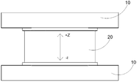
- FIG. 4 is a side elevational view of the MEMS system in accordance with the above-described preferred embodiment of the present invention, illustrating movement of a lens barrel along the Z-axis.
- Figure 5 illustrates the movement of the lens barrel when a thermal MEMS actuator is powered, in accordance with the above-described preferred embodiment of the present invention.
- Figure 6 is a perspective view of a thermal micro-actuator in accordance with the above-described preferred embodiment of the present invention.
- Figure 7 is a perspective view of a microfin according to the above-described preferred embodiment of the present invention, illustrating a braided microfin with a polymer filled gap.
- Figure 8 illustrates a micro-heater in accordance with the above-described preferred embodiment of the present invention, wherein the micro-heater is positioned on top of the micro-fin.
- Figure 9 is a braided skeleton in accordance with the above-described preferred embodiment of the present invention, wherein the braided skeleton has a gap for filling the polymer.
- FIGS 10A through 10D illustrate different designs of the microfins in accordance with the above-described preferred embodiments of the present invention.
- Figure 11 illustrates the bending motion of the thermal micro-actuator in accordance with the above-described preferred embodiment of the present invention.
- Figure 12 is a perspective view of the micro-heater on the thermal micro-actuator in accordance with the above-described preferred embodiment of the present invention.
- FIG. 13 illustrates an integrated heating circuit in accordance with the above-described preferred embodiment of the present invention.
- Figure 14 illustrates the central position (at voltage zero) of the lens barrel in accordance with the above-described preferred embodiment of the present invention, wherein the lens barrel floats as the ambient temperature changes.
- Figure 15 illustrates an ambient temperature independent fixed reference point for obtaining the lens barrel by preheating in accordance with the above preferred embodiment of the present invention.
- 16 is a perspective view of a differential system having two MEMS devices applied to the lens barrel in accordance with the above-described preferred embodiment of the present invention.
- Figure 17 is a side elevational view of two MEMS devices for the lens barrel in accordance with the above-described preferred embodiment of the present invention.
- Figure 18 illustrates the lens barrel between the two MEMS devices in accordance with the above-described preferred embodiment of the present invention, wherein the relative arrangement of the two MEMS devices causes the lens barrel to not move with changes in ambient temperature.
- Figure 19 illustrates the energy supply of the MEMS tip and the low end to move the lens barrel in accordance with the above-described preferred embodiment of the present invention.
- FIG. 20 is a perspective view of a MEMS system having a lens barrel in accordance with an alternative embodiment of the above-described preferred embodiment of the present invention.
- FIG. 21 is a perspective view of the MEMS system without the lens barrel of the alternative embodiment in accordance with the above-described preferred embodiment of the present invention.
- Figure 22 illustrates an independent microdrive module of the alternative embodiment in accordance with the above-described preferred embodiment of the present invention.
- Figure 23 illustrates an alternative micro-drive module of the alternative embodiment in accordance with the above-described preferred embodiment of the present invention supporting the lens barrel through a micro-driver without the need for any frame.
- Figure 24 illustrates the stand-alone micro-drive module of the alternative embodiment in accordance with the above-described preferred embodiment of the present invention, wherein the stand-alone micro-drive module is disposed in a PCB circuit to provide control.
- FIG. 25 illustrates the mounting of the lens barrel on the thermal micro-driver of the alternative embodiment in accordance with the above-described preferred embodiment of the present invention, wherein the thermal micro-driver is secured to the PCB.
- Figure 26 illustrates a synchronous control circuit of the alternative embodiment in accordance with the above-described preferred embodiment of the present invention.
- Figure 27 is a circuit diagram of the synchronous control circuit of the alternative embodiment in accordance with the above-described preferred embodiment of the present invention.
- Figure 28 illustrates a separate, independent mobile control circuit of the alternative embodiment in accordance with the above-described preferred embodiment of the present invention.
- Figure 29 is a circuit diagram showing the separate independent movement control of the alternative embodiment of the above preferred embodiment of the present invention.
- Figure 30 illustrates the control of the Z-axis and tilt of the lens barrel in accordance with this alternative embodiment of the above-described preferred embodiment of the present invention. Control method.
- Figure 31 illustrates the camera module being mounted in a handset for autofocusing in accordance with the above-described preferred embodiment of the present invention.
- Figure 32 illustrates that the operation of these microactuators in accordance with the above-described preferred embodiments of the present invention are separately controlled to rotate the lens barrel to achieve anti-shake along different axes.
- Figure 33 illustrates the control of the lens barrel by selectively activating at least one micro-driver to rotate the lens barrel in accordance with the above-described preferred embodiment of the present invention.
- Figure 34 illustrates a manufacturing process of the micro-driver in accordance with the above-described preferred embodiment of the present invention.
- the term “a” is understood to mean “at least one” or “one or more”, that is, in one embodiment, the number of one element may be one, and in other embodiments, the element The number can be multiple, and the term “a” cannot be construed as limiting the quantity.
- the present invention is applicable to microelectromechanical systems (MEMS) because of its small size and fast, precise positioning. In contrast, conventional designs have driving and travel limitations that are rarely used.
- MEMS microelectromechanical systems
- the system of the present invention utilizes a thermal micro-driver to position the lens barrel in a handset camera module.
- the hot micro-driver can provide a larger driving force and a longer stroke to meet the needs of the camera module.
- the system can be configured to achieve up to three-axis (XYZ) positioning control.
- the present invention also discloses a method of obtaining a thermal drive system in which the thermal drive system is independent of ambient temperature.
- a camera module in accordance with the present invention is mounted to a portable electronic device, such as a smart phone, to provide the camera module with an auto focus function.
- a portable electronic device such as a smart phone
- the present invention can be applied to different portable electronic devices, such as a notebook computer or a tablet computer.
- FIGs 2 to 4 a preferred implementation in accordance with the present invention
- a camera module of the example is disclosed.
- the camera module includes a base 10, a lens barrel 20 and a lens barrel positioning device 30.
- the base 10 is adapted to be mounted to a portable electronic device.
- the barrel 20 supports at least one optical lens therein and is adapted to move along the Z axis.
- the barrel positioning device 30 is provided for selectively adjusting the position of the barrel 20 to provide an autofocus function.
- the barrel positioning device 30 includes at least two micro-actuators 31 and a control unit 32.
- the microactuators 31 are operatively coupled between the base 10 and the barrel 20 and are positioned such that the microactuators 31 extend radially from the barrel 20, wherein each microdrive 31 is configured to Bent by heat.
- the control unit 32 includes at least one heating circuit 321 .
- the heating circuit 321 is operatively coupled to the micro-actuators 31 to controllably provide thermal energy to each micro-driver, wherein each micro-driver reacts to thermal energy applied thereto for corresponding bending, thereby
- the base 10 moves the lens barrel to control the three-axis positioning of the lens barrel 20.
- the present invention is arranged such that the base 10 includes a bracket 11 and a step 12 for fixing the barrel 20, a heating unit of the heating circuit 321, and the thermal microactuator 31 (thermal bimorph) ),As shown in Figure 3.
- the bracket 11 is a frame having four opposing corners. Specifically, the bracket 11 has a cavity 111. Preferably, the frame cavity 111 is formed at a central portion of the bracket 11. Accordingly, at least one optical lens is mounted to the lens barrel 20. Preferably, the optical lens can be securely secured within the barrel 20 such that a beam of light can pass through the barrel 20 and through the optical lens therein.
- micro-actuators 31 are used to replace the voice coil motor (VCM) that is widely used in the autofocus of smartphone camera modules.
- VCM voice coil motor
- a series of analytical designs and experimental validations are planned to be planned to optimize the design of the drive that provides autofocus.
- the technical prototype of the MEMS driver is implemented in SU8 lithography and deep silicon etching.
- micro-actuators 31 are symmetrically disposed around the lens barrel 20. According to one embodiment, four microactuators 31 are disposed at the four corners of the bracket 11. In other words, according to this embodiment, the thermal unimorphs 31 are preferably disposed at the four corners of the bracket 11 and surround the periphery of the frame cavity 111, as shown in FIG.
- the barrel 20 is mounted to the step 12 of the base 10.
- the lens barrel 20 is moved together with the thermal micro-actuators 31, wherein the thermal micro-actuators 31 are bent out of plane when thermally activated by resistance, as shown in FIG.
- the rigid support 11 forming the susceptor 10 is made of single crystal silicon as shown in Figs. 2 and 3.
- the holder 11 functions as a heat sink for these thermo microactuators 31 and has a function as a support for the device according to the present invention.
- the bracket 11 is the basis for the interconnection of the micro-actuators 31 and the overall circuit of the control unit 32.
- the center step 12 is disposed in the frame cavity 111 and is coupled to the bracket 11 via the micro-actuators 31. When thermal energy is supplied to these microactuators 31, the step 12 moves (out of plane).
- the barrel 20 is mounted to the central step 12 for positioning.
- the integrated circuit of control unit 32 forms a resistive heater to provide the thermal energy required for operation of these thermal microactuators 31.
- the overall circuit of the control unit 32 can connect all the micro-drivers 31 to the device in one circuit, therefore, It is possible to realize that all the micro drivers 31 are simultaneously driven by one input.
- the micro-actuators 31 are controllably bent to pass a photosensitive light passing through the step 12 and along a photosensitive chip of the holder 11 disposed in the camera module.
- the path moves the lens barrel 20 within the cavity 11.
- the positioning of the plurality of micro-actuators 31 is also very important. Positioning the plurality of micro-actuators 31 in a symmetrical manner can reduce axial offset motion, such as tilting, to achieve linear motion of the lens barrel 20. Preferably, three points may define a plane, and therefore, preferably, at least three micro-actuators 31 are required for proper positioning of the barrel 20. According to the preferred embodiment, the apparatus is provided with four microactuators 31, wherein the four microactuators 31 are symmetrically disposed at four opposite angles to make full use of the space, thereby making the design more compact.
- each micro-driver 31 includes a plurality of honeycomb-shaped micro-fins 311 and a plurality of polymer thermal expansion elements 312 that are filled in a plurality of fin gaps 310. Activation of these micro-actuators 31 is achieved by electrical resistance heating of an integrated micro-heater 313.
- the polymeric thermal expansion element 312 is a thermally expandable polymer.
- Each micro-drive 31 further includes a back bone 314 coupled to one side of each micro-fin 311, wherein the micro-heater 313 is disposed on the other side of each micro-fin 311 to be operatively coupled to the Heating circuit 321.
- the silicon backing 314 is bent by the polymeric thermal expansion element 312 as the polymeric thermal expansion element 312 expands the silicon fin gap 310.
- the difference in thermal expansion between the driver backing bone 314 and the polymer component of the polymeric thermal expansion element 312 creates thermal stresses on the microactuators 31, thereby causing the microactuator to bend negatively downward along the Z axis, as shown in FIG. Show.
- the micro-fins 311 of the braid shape are like a heat conductor between the micro-heater 313 of each micro-actuator 31 and the thermal expansion element 312.
- Each microfin 311 further serves as a drive beam extending between the bracket 11 and the step 12.
- the microfin 311 also has a planar confinement effect on the thermal expansion element (i.e., the thermally expandable polymer shown in Fig. 6) to concentrate the volumetric thermal expansion in the driving direction. In other words, when electrical energy is supplied, the thermal expansion element 312 will expand under the action of heat.
- the difference in expansion between the driver back bone 314 and the polymer 312 causes the micro-actuators 31 to generate thermal stresses, thereby causing the micro-actuators 31 to bend down the Z-axis toward the susceptor 10, as shown in FIG.
- These microactuators 31 are symmetrically arranged to counteract all of the axis offset motion, thereby moving the step 12 in a straight line, thereby minimizing the tilt of the barrel.
- the back bone 314 to the micro fin 311 serves as a basic structure, like a rigid layer of a bilayer driver.
- the back bone 314 has good heat conduction properties, and it connects each fin of the micro fin 311 as shown in FIG.
- the microheater 313 extends along the meandering skeleton of the curved thermal microactuator 31.
- the crucible skeleton has a dual function of thermally conductive medium and limiting the thermally expandable polymer of the polymeric thermal expansion element 312 that is filled in the fin gap 310.
- the micro-actuator 31 is embodied as a thermally driven Si/Su-8 composite micro-actuator that imparts an imaging mode to a portable electronic device.
- a carrier and the barrel 20 are connected to each other on the annular silicon step.
- Each of the drive beams is embodied as a silicon plate SU-8 that is filled between the crucible structure and a platinum film heater.
- the silicon wafer can effectively transfer heat to the interlayer SU-8.
- the Si-SU-8 composite is heated by the platinum film heater by resistance heating, the Si-SU-8 drive beam can only produce out-of-plane bending, of which four Si-SU-8 Simultaneous activation of the drive beam (microactuator) allows the annular silicon step to bend in the Z-axis direction, as shown in FIG.
- FIG. 10(A) discloses the meandering shape of the microfin 311.
- FIG. 10(B) discloses a double-twist shape of the micro-fin 311.
- FIG. 10(C) discloses a three-turn shape of the micro-fin 311.
- FIG. 10(D) discloses a half-turn/semi-parallel combination structure of the micro-fin 311.
- FIGS. 10(A) to (C) respectively disclose top views of the entire length, half length, and one-third length of the silicon germanium structure of the film heater.
- Figure 10 (D) discloses that one half of the silicon beam is a braided structure on which the heater is placed. The other half of the silicon beam is formed by a parallel silicon plate.
- the simulation result shows that the three-turn design with one-third length heater is directed to the entire driving beam. Provide the most balanced exclusion. If the drive beam is scaled to the FEM simulation system, it produces the largest displacement.
- the table below illustrates the performance and/or heater length of various Si-SU-8 drive beams with different lengths. In the mask design, there are twelve designs depending on the length of the drive beam (width and thickness are fixed to 415 ⁇ m and 15 ⁇ m, respectively) and/or heater length:
- SP width 5 ⁇ m
- SP gap 10 ⁇ m
- T 1 10 ⁇ m
- T 2 5 ⁇ m
- the integrated micro-heater 313 includes at least one conductive metal film to match the shape of the micro-fin 311 and is coupled to the micro-fin 311, wherein the conductive metal film has high impedance and High temperature stability.
- the conductive metal film generates heat when current is passed.
- all of the microheaters 313 are connected to a circuit of the control unit 32 for simultaneous control by the same input, as shown in FIG.
- the microheater 313 is a platinum film heater.
- the shape of the crucible of the microfin 311 increases its contact area with the microheater 313, thereby facilitating the supply of heat therefrom and increasing the heat conduction between the back bone 314 and the polymer thermal expansion element 312. Area to carry out heat transfer.
- each microactuator 31 is designed to have a footprint of 9.28 mm x 9.28 mm x 0.5 mm (sheet thickness).
- These microactuators 31 are composed of four heat driven beams.
- the heat driven beam is coupled to a circular silicon step.
- the circular silicon step has a diameter of 6.78 mm.
- the step 12 and the barrel 20 are attached by the heat drive beam.
- the circular silicon step 12 is etched to form a groove to maximize the driving in the Z-axis direction along the photosensitive path of the photosensitive chip.
- the drive beam of each micro-actuator 31 is embodied as a braided silicon wafer SU-8 that is filled between the crucible structure and a platinum film heater.
- the silicon wafer of the microfin 311 can efficiently transfer heat to the interlayer: the polymeric thermal expansion element 312. Due to the constraint of the silicon back bone 314, when the thermal expansion element 312 is resistively heated by the platinum film heater 313, the micro-actuators 31 can only produce out-of-plane bending. Simultaneous activation of the four microactuators 31 can cause the annular silicon step 12 to bend in the Z-axis direction, as shown in FIG. 12, thereby moving the step 12 and the entire carrier of the lens barrel 20 downward to provide an autofocus function. .
- bendable thermal microactuators 31 such as bimetallic materials or thermal bimolecular films, can be used for such out-of-plane positioning systems.
- a suitable drive needs to respond quickly to low battery demands. Its demand for electricity is no more than the energy input to a VCM.
- the hot microdrive 31 is selected due to its large stroke and rapid response. Further, these micro-actuators 31 can be operated without excessive heating which is disadvantageous to the improvement of image quality.
- SU-8 has a high coefficient of thermal expansion (50-150 ppm/°C), a Young's modulus (3 GPa), and a Poisson's ratio (0.3).
- the ideal thermally expandable polymer used to make the hot bimorph should have a high coefficient of thermal expansion (>150 ppm/°C) and a Young's modulus (>1 GPa).
- the polymeric thermal expansion element 312 should also be nearly incompressible (Poisson's ratio 0.49 to 0.5) to maximize thermal stress and tension in the stroke direction.
- a typical polymer suitable for the above requirements is a silicone based resin (Corning WL-5150 photopatternable silicon).
- these micro-actuators 31 are embodied as Si/SU-8 micro-actuators made of MEMS drivers that require six templates for fabrication, with the first and third templates being the same type of template.
- the manufacturing method of these micro-actuators 31 includes the following steps:
- Step 1 deposit a layer of 100 nm thick Si 3 N 4 on both sides of the SOI (Silicon On Insulator) wafer, wherein the front side Si 3 N 4 is imaged by photolithography and CF4 plasma etching. .
- the etched area on the top side of the substrate is reserved for Si to form the drive beam structure.
- Step 2 spraying 20 nm of Ti (titanium) on the top side of the photoresist pattern of the substrate, followed by spraying 200 nm of Pt (platinum) and 80 nm of Au (gold), wherein the final heater is obtained after removing the photoresist in the stripping process. pattern.
- Step 3 The bonding pad area is covered with the template of Step 1 so that the Au layer on the platinum film heater is removed.
- Step 4 The Si microstructure was fabricated by a reactive ion deep etching (DRIE) technique (the parallel plates were bent). Etching is performed on the device layer until the desired thickness is reached and etching is complete.
- DRIE reactive ion deep etching
- Step 5 A SU-8 resist is molded into the gap between the etched silicon microstructures to form a Si/SU-8 composite. when After the silicon microstructure is filled with SU-8, the pattern is formed by standard photolithography.
- Step 6 A Si 3 N 4 pattern is formed on the back side of the wafer by photolithography and CF 4 plasma etching, wherein a substrate is formed by DRIE to the substrate.
- Step 7 The buried oxide layer is etched by a wet HF etch or a CF 4 plasma etch technique to form a MEMS driver.
- Step 8 The above-described processed substrate was baked at a temperature of 120 ° C for 1 hour on a hot plate and the drive beam was supported by mechanical division (shown by arrows in Fig. 34) to separate a single MEMS micro-actuator from the wafer.
- each micro-actuator 31 hot bimorph
- the center position (voltage of 0) of the positioning step of the lens barrel 20 changes as the temperature environment changes, as shown in FIG. Without a defined reference starting point, the temperature dependent offset of the step positioning causes the system to have no positioning control reference.
- the thermal microdrive 31 can be affected by ambient temperature and thus may not be suitable for system positioning.
- the present invention discloses two apparatus positioning methods that are independent of ambient temperature.
- the first method is to preheat the microactuators 31 to a reference temperature point, i.e., above the operating ambient temperature. Heating beyond this reference temperature point enables positioning control to be achieved, as shown in FIG.
- the first method is to preheat the micro-actuators 31 to the reference temperature point, wherein the reference temperature point exceeds most of the ambient temperatures applied in the prior art. Any temperature change at this reference temperature point is calibrated and then used for positioning.
- each micro-driver 31 is preheated by the heater circuit 321 to the reference temperature point to calibrate the central position of the lens barrel 20 independent of ambient temperature changes, so that when each micro-driver 31 is used by the heater circuit 321 When heated to the above reference temperature point, the micro-actuators 31 are bent to move the lens barrel 20 from its central position.
- the second method is based on another differential system as shown in Figures 16-18.
- the two sets of micro-actuators 31, namely a top set of micro-actuators and a bottom set of micro-actuators, are arranged in parallel and oppositely at any ambient temperature, as shown in Figures 16 to 18, so that the lens barrel 20 is only in the two sets of relative Move when the temperature between the set microdrives is different, as shown in Figure 18.
- the micro-actuators 31 are arranged to have a top set of micro-actuators 31 coupled to the lens barrel 20 and a bottom-bottom set micro-driver 31 coupled to the barrel 20. Therefore, the lens barrel 20 is maintained at a central position under different ambient temperature conditions.
- the heater circuit 321 can either supply energy to the top set of micro-actuators 31 or provide energy to the bottom set of micro-actuators 31 to control the movement of the lens barrel 20, as shown in FIG.
- the positioning of the lens barrel 20 is cancelled to be maintained at the center position, thus The lens barrel 20 is held at a central position without being affected by the ambient temperature.
- Any change in the environment caused by the change in the top set of micro-actuators 31 is offset by the opposing forces generated by the bottom set of micro-actuators 31 (lens barrel).
- the top set of micro-actuators 31 are extended between the top bracket 11 and the top step 12.
- the bottom set microactuator 31 is extended between the bottom bracket 11 and the bottom step 12 as shown in FIG.
- the top set of micro-actuators 31 and the bottom set of micro-actuators 31 are aligned with each other such that the top set of micro-drivers 31 are disposed face to face with the bottom set of micro-drivers 31. Therefore, when the top group micro-actuator 31 generates a bending motion due to a change in the ambient temperature, thereby generating a force, the force generated by the bottom group micro-actuator 31 cancels the force generated by the top group micro-actuator 31.
- a housing is provided for receiving the top set of microdrives 31 and the bottom set of microdrives 31 therein.
- each top or bottom set of microdrives includes at least one microdrive 31.
- the stroke in one direction is reduced to half, the overall stroke that can be achieved is the same as that of configuring a micro-driver 31. Therefore, this two-layer or two-group structure allows the lens barrel 20 to be disposed in the middle of the entire stroke, thereby achieving fast autofocus. It is also more stable in structure.
- the lens barrel 20 can be moved up and down to achieve autofocus.
- the stability of the image can be achieved by activating these micro-drivers 31. Accordingly, when the selected micro-driver 31 (not all of these micro-actuators 31) is activated, the lens barrel 20 can be rotated about the same axis.
- FIG. 20 an alternate embodiment of the above-described preferred embodiment is illustrated in which an alternative embodiment of the base 10 is illustrated.
- the step 12 is removed.
- the lens barrel 20 is directly disposed at the end of these micro-actuators 31 as shown in FIG.
- the barrel 20 is attached to the mounting point by a glue/mechanical method, as shown in FIG.
- the micro-actuators 31 extend radially from the bracket 11 to couple the peripheral wall of the lens barrel 20, thereby supporting the lens barrel 20 in the frame cavity 111 and driving the lens barrel 20.
- the bracket 11 does not require a single integrated circuit but can be replaced by at least two base blocks 11A.
- Each of the base blocks 11A is provided with a micro-driver 31 as shown in FIGS. 23 and 25. In other words, the bracket 11 may not be provided.
- These micro-actuators 31 are respectively disposed on a single base block 11A. All microdrives 31 can be controlled by the same circuit with a single power supply to achieve the same effect as the base mechanism, which is primarily Z-axis positioning control.
- the single base block 11A can also be mounted to the bracket 11, as shown in Figures 24 and 25.
- Each microdrive 31 can be controlled by circuitry of the control unit 32, such as a printed circuit, as shown in Figures 26 and 27.
- the lens barrel 20 can be mounted by the same method in which no step is provided, as shown in FIG.
- Driving the micro-actuator with a single power supply can achieve the same effect as the basic structure, which is mainly the positioning control in the Z-axis direction, as shown in FIGS. 26 and 27.
- each individual pedestal block 11A can also be controlled by a single circuit of the control unit 32, wherein each module 11A is controlled by a plurality of power sources and a microprocessor, respectively, such that the lens barrel ( The rotation around the x and y axes) enables tilting movement on the basis of the Z-axis movement, thereby performing three-axis positioning control as shown in FIG.
- microactuators 31 are mounted to the four corners of the bracket 11 and are directly connected to the step 12 or the barrel 20, i.e., no circular silicon steps connecting the four beams are provided.
- the camera module also has better image stability.
- Each microdrive 31 has an elongated structure to form a beam.
- these micro-actuators 31 with separate control beams have an auto-focus function and the image is stable.
- micro-actuators 31 can still be activated simultaneously to complete auto-focus similar to the integrated micro-driver, as shown in Figure 2.
- the single beam, the pair of double beams or the three beams can be controlled to be driven in such a manner that the hand shake can be compensated along different axes. If only the beams 1 and 2 of these micro-actuators 31 are used as a pair, or the beams 3 and 4 of these micro-actuators 31 are simultaneously activated as a pair, the barrel 20 is rotated about the x-x' axis.
- the lens barrel 20 is rotatable about the y-y' axis.
- the drive beam 2 of these microactuators 31 and the beams 4 of these microactuators 31 are necessary.
- the drive beams 1, 2 and 3 of these micro-actuators 31 or the beams 1, 3 and 4 of these micro-actuators 31 can also simultaneously drive the barrel 20 to rotate about the u-u' axis.
- only the drive beam 1 or 3 of these micro-actuators 31 can rotate the barrel 20 about the v-v' axis.
- the drive beams 1, 2 and 4 of these microactuators 31 or the beams 2, 3 and 4 of these microactuators 31 can simultaneously rotate the barrel 20 about the v-v' axis.
- a single beam of the micro-actuators 31 or a set of beams of the micro-actuators 31 can be simultaneously driven to cause the barrel 20 to perform a preset rotation.
- the lens barrel 20 is rotatable about the x-axis.
- rotation of the barrel 20 about other axes can be achieved by a combination of different drive beams of the top and bottom set microactuators 31.
- the lens barrel 20 can be rotated about the y-y' axis as shown in Fig. 33(a).
- the lens barrel 20 can be rotated about the y-y' axis as shown in Fig. 33(b).
- the camera module has fewer structural components than the VCM driven camera module. Accordingly, the VCM-driven camera module with only the autofocus function includes twelve components. The VCM camera module with autofocus function and image stability guarantees at least 16 components. Fewer structural components make the assembly process simpler and reduce the production cost of the camera module. According to the present invention, the camera module having these micro-actuators 31 can have only 7 to 11 components.
- the camera module includes only two support members formed by high performance nylon spray molding.
- the top support element acts primarily as a cover to provide an anti-tilt structure on the inner side wall of the opening.
- These microactuators 31 are disposed on the top surface of the bottom support member (base). A limiter capable of resisting vibration is integrally molded to the bottom support member.
- Another advantage of the present invention is that precise driving results in improved image quality. Due to overshoot and oscillation, the lens driven by the VCM can only be fixed at a position 100-200 ms away from the target position. Noise can be achieved by using a self-calibrating VCM driver get over. After the sound is compensated, the VCM's fast positioning sound is small.
- these thermal microactuators 31 are integrated with sliders and assembled into a printed circuit for performance testing. This two-stage microactuator 31 interprets accurate, fast, and silent displacement (20nm/1KHz).
- the measured displacement of these microactuators 31 according to the invention indicates that there is no loud noise, so the four drive beams of these microactuators 31 are rigidly arranged. The great reduction in the sound makes the image quality higher and the image clearer.
Landscapes
- Engineering & Computer Science (AREA)
- Chemical & Material Sciences (AREA)
- Combustion & Propulsion (AREA)
- Physics & Mathematics (AREA)
- Mechanical Engineering (AREA)
- General Engineering & Computer Science (AREA)
- General Physics & Mathematics (AREA)
- Optics & Photonics (AREA)
- Analytical Chemistry (AREA)
- Lens Barrels (AREA)
- Studio Devices (AREA)
Abstract
L'invention concerne un dispositif à système microélectromécanique (MEMS) qui utilise des micro-éléments de commande (31) pour positionner un barillet d'objectif (20) dans un appareil intelligent, tel qu'un module de photographie d'un téléphone mobile. Les micro-éléments de commande s'étendent radialement par rapport à un barillet d'objectif. Chaque micro-éléments de commande est pliable sous l'effet de la chaleur. Une unité de commande (32) comprend un circuit de chauffage (321) connecté de manière fonctionnelle au micro-élément de commande de façon à appliquer de manière commandable une énergie thermique à chaque micro-élément de commande. Chaque micro-éléments de commande se plie de façon correspondante pour déplacer le barillet d'objectif par rapport à une base (100), ce qui permet de commander le positionnement de trois axes des barillets d'objectif. Le fonctionnement du micro-élément de commande n'est pas affecté par un changement de la température de l'environnement.
Priority Applications (1)
| Application Number | Priority Date | Filing Date | Title |
|---|---|---|---|
| CN201780014709.9A CN108780206B (zh) | 2016-03-03 | 2017-03-03 | 用于镜筒定位的微机电系统装置 |
Applications Claiming Priority (2)
| Application Number | Priority Date | Filing Date | Title |
|---|---|---|---|
| SG10201601620W | 2016-03-03 | ||
| SG10201601620W | 2016-03-03 |
Publications (1)
| Publication Number | Publication Date |
|---|---|
| WO2017148434A1 true WO2017148434A1 (fr) | 2017-09-08 |
Family
ID=59722134
Family Applications (1)
| Application Number | Title | Priority Date | Filing Date |
|---|---|---|---|
| PCT/CN2017/075568 Ceased WO2017148434A1 (fr) | 2016-03-03 | 2017-03-03 | Dispositif à système microélectromécanique pour positionner un barillet d'objectif |
Country Status (3)
| Country | Link |
|---|---|
| US (1) | US10564385B2 (fr) |
| CN (1) | CN108780206B (fr) |
| WO (1) | WO2017148434A1 (fr) |
Cited By (3)
| Publication number | Priority date | Publication date | Assignee | Title |
|---|---|---|---|---|
| CN108121046A (zh) * | 2017-12-29 | 2018-06-05 | 宁波舜宇光电信息有限公司 | 一种驱动组件、镜头组件及其自动对焦的摄像模组 |
| WO2020029821A1 (fr) * | 2018-08-07 | 2020-02-13 | 宁波舜宇光电信息有限公司 | Appareil de caméra, dispositif d'entraînement d'alliage à mémoire de forme (sma) et procédé de fabrication, procédé d'entraînement et procédé de câblage associés |
| TWI846118B (zh) * | 2022-09-22 | 2024-06-21 | 新煒科技有限公司 | 取像模組及電子設備 |
Families Citing this family (12)
| Publication number | Priority date | Publication date | Assignee | Title |
|---|---|---|---|---|
| US11159105B2 (en) * | 2017-07-14 | 2021-10-26 | Purdue Research Foundation | Light responsive polymer magnetic microrobots |
| CN107659759B (zh) * | 2017-09-28 | 2020-10-23 | 宁波舜宇仪器有限公司 | 摄像模组 |
| CN111698398B (zh) * | 2019-03-15 | 2025-04-18 | 宁波舜宇光电信息有限公司 | 摄像装置、sma驱动器及其驱动方法 |
| CN111629125B (zh) * | 2019-02-28 | 2025-03-28 | 宁波舜宇光电信息有限公司 | 摄像装置、sma驱动设备及其制造方法和驱动方法 |
| US11522472B2 (en) * | 2018-09-26 | 2022-12-06 | MEMS Drive (Nanjing) Co., Ltd. | MEMS actuation system |
| CN111988512B (zh) * | 2020-08-31 | 2022-05-13 | 维沃移动通信有限公司 | 电子设备及其摄像头模组 |
| CN114326005A (zh) * | 2020-09-25 | 2022-04-12 | 麦斯卓有限公司 | Mems致动系统 |
| CN114911064B (zh) * | 2021-02-09 | 2024-10-18 | 苏州佳世达光电有限公司 | 光学扫描装置校正套件 |
| CN115145047A (zh) * | 2021-03-29 | 2022-10-04 | 台湾东电化股份有限公司 | 光学系统及其防手震补偿方法 |
| CN219625775U (zh) * | 2022-01-14 | 2023-09-01 | 台湾东电化股份有限公司 | 光学驱动机构 |
| CN117897647A (zh) * | 2022-03-07 | 2024-04-16 | 麦斯卓微电子(南京)有限公司 | Mems透镜/图像传感器组件和工艺流程 |
| CN114637126B (zh) * | 2022-05-18 | 2022-09-13 | 江西联创电子有限公司 | 一种光学稳像镜头及其组装方法 |
Citations (7)
| Publication number | Priority date | Publication date | Assignee | Title |
|---|---|---|---|---|
| US20070216888A1 (en) * | 2004-04-14 | 2007-09-20 | Jens Kugler | Support Device for Positioning an Optical Element |
| CN102902039A (zh) * | 2012-10-23 | 2013-01-30 | 无锡微奥科技有限公司 | 一种基于微机电系统的自动对焦镜头 |
| US8730599B2 (en) * | 2012-10-01 | 2014-05-20 | Apple Inc. | Piezoelectric and MEMS actuator |
| US20150002726A1 (en) * | 2006-11-09 | 2015-01-01 | Digitaloptics Corporation | Integrated lens barrel, actuator, and mems snubber systems and methods |
| US20150146312A1 (en) * | 2010-11-15 | 2015-05-28 | Digitaloptics Corporation | Mems electrical contact systems and methods |
| CN105159009A (zh) * | 2010-05-20 | 2015-12-16 | Lg伊诺特有限公司 | 相机模块 |
| CN105209950A (zh) * | 2013-03-15 | 2015-12-30 | 数位光学Mems有限公司 | 微型mems致动器组件 |
Family Cites Families (4)
| Publication number | Priority date | Publication date | Assignee | Title |
|---|---|---|---|---|
| US5720169A (en) * | 1995-05-23 | 1998-02-24 | Schneider; Edward T. | Thermochemical/mechanical actuator |
| US8768157B2 (en) * | 2011-09-28 | 2014-07-01 | DigitalOptics Corporation MEMS | Multiple degree of freedom actuator |
| KR102047373B1 (ko) * | 2012-07-30 | 2019-11-21 | 엘지이노텍 주식회사 | 카메라 모듈 |
| EP3926379A1 (fr) * | 2014-01-28 | 2021-12-22 | Lg Innotek Co. Ltd | Unité de déplacement de lentille et module de caméra la contenant |
-
2017
- 2017-02-07 US US15/426,997 patent/US10564385B2/en active Active
- 2017-03-03 WO PCT/CN2017/075568 patent/WO2017148434A1/fr not_active Ceased
- 2017-03-03 CN CN201780014709.9A patent/CN108780206B/zh active Active
Patent Citations (7)
| Publication number | Priority date | Publication date | Assignee | Title |
|---|---|---|---|---|
| US20070216888A1 (en) * | 2004-04-14 | 2007-09-20 | Jens Kugler | Support Device for Positioning an Optical Element |
| US20150002726A1 (en) * | 2006-11-09 | 2015-01-01 | Digitaloptics Corporation | Integrated lens barrel, actuator, and mems snubber systems and methods |
| CN105159009A (zh) * | 2010-05-20 | 2015-12-16 | Lg伊诺特有限公司 | 相机模块 |
| US20150146312A1 (en) * | 2010-11-15 | 2015-05-28 | Digitaloptics Corporation | Mems electrical contact systems and methods |
| US8730599B2 (en) * | 2012-10-01 | 2014-05-20 | Apple Inc. | Piezoelectric and MEMS actuator |
| CN102902039A (zh) * | 2012-10-23 | 2013-01-30 | 无锡微奥科技有限公司 | 一种基于微机电系统的自动对焦镜头 |
| CN105209950A (zh) * | 2013-03-15 | 2015-12-30 | 数位光学Mems有限公司 | 微型mems致动器组件 |
Cited By (4)
| Publication number | Priority date | Publication date | Assignee | Title |
|---|---|---|---|---|
| CN108121046A (zh) * | 2017-12-29 | 2018-06-05 | 宁波舜宇光电信息有限公司 | 一种驱动组件、镜头组件及其自动对焦的摄像模组 |
| WO2020029821A1 (fr) * | 2018-08-07 | 2020-02-13 | 宁波舜宇光电信息有限公司 | Appareil de caméra, dispositif d'entraînement d'alliage à mémoire de forme (sma) et procédé de fabrication, procédé d'entraînement et procédé de câblage associés |
| US12353050B2 (en) | 2018-08-07 | 2025-07-08 | Ningbo Sunny Opotech Co., Ltd | Camera apparatus, SMA driving device and manufacturing method, driving method and wiring method thereof |
| TWI846118B (zh) * | 2022-09-22 | 2024-06-21 | 新煒科技有限公司 | 取像模組及電子設備 |
Also Published As
| Publication number | Publication date |
|---|---|
| US10564385B2 (en) | 2020-02-18 |
| US20170254978A1 (en) | 2017-09-07 |
| CN108780206A (zh) | 2018-11-09 |
| CN108780206B (zh) | 2021-02-09 |
Similar Documents
| Publication | Publication Date | Title |
|---|---|---|
| CN108780206B (zh) | 用于镜筒定位的微机电系统装置 | |
| JP5311884B2 (ja) | 携帯用および固定用ビデオカメラの小型低コストパン/チルト磁気作動 | |
| US10082652B2 (en) | Miniaturized optical zoom lens system | |
| TWI557061B (zh) | Movable vehicle structure for microelectromechanical systems | |
| CN107209347B (zh) | 自动聚焦相机以及旨在集成到此类相机中的具有可变焦距的光学设备 | |
| US20080225419A1 (en) | Varifocal mirror and camera module comprising the same | |
| CN110673297A (zh) | 微型光学镜头自动对焦及防抖的驱动装置 | |
| TW201115205A (en) | Wafer level optical system | |
| CN111552052A (zh) | Sma致动器及镜头驱动装置 | |
| US10393991B2 (en) | MEMS device | |
| JP2002228903A (ja) | 光学ユニット | |
| CN115427679A (zh) | 致动器组件 | |
| TW200946953A (en) | Optical lens image stabilization systems | |
| JP4642659B2 (ja) | 可変ミラー | |
| JP2009196060A (ja) | 駆動機構 | |
| JP2008211864A (ja) | 駆動装置、撮像ユニットおよび撮像装置 | |
| JP5521553B2 (ja) | アクチュエータ機構 | |
| JP2010169800A (ja) | 駆動装置、および撮像装置 | |
| KR20100019688A (ko) | 탄소나노튜브를 포함하는 구동 액츄에이터 | |
| KR102107584B1 (ko) | 멤스 소자 | |
| CN117082322A (zh) | 影像撷取装置及光学致动模块 |
Legal Events
| Date | Code | Title | Description |
|---|---|---|---|
| NENP | Non-entry into the national phase |
Ref country code: DE |
|
| 121 | Ep: the epo has been informed by wipo that ep was designated in this application |
Ref document number: 17759285 Country of ref document: EP Kind code of ref document: A1 |
|
| 122 | Ep: pct application non-entry in european phase |
Ref document number: 17759285 Country of ref document: EP Kind code of ref document: A1 |