WO2017149593A1 - 回転電機及び回転電機の製造方法 - Google Patents
回転電機及び回転電機の製造方法 Download PDFInfo
- Publication number
- WO2017149593A1 WO2017149593A1 PCT/JP2016/056032 JP2016056032W WO2017149593A1 WO 2017149593 A1 WO2017149593 A1 WO 2017149593A1 JP 2016056032 W JP2016056032 W JP 2016056032W WO 2017149593 A1 WO2017149593 A1 WO 2017149593A1
- Authority
- WO
- WIPO (PCT)
- Prior art keywords
- groove
- core
- frame
- circumferential direction
- rotating electrical
- Prior art date
- Legal status (The legal status is an assumption and is not a legal conclusion. Google has not performed a legal analysis and makes no representation as to the accuracy of the status listed.)
- Ceased
Links
Images


Classifications
-
- H—ELECTRICITY
- H02—GENERATION; CONVERSION OR DISTRIBUTION OF ELECTRIC POWER
- H02K—DYNAMO-ELECTRIC MACHINES
- H02K1/00—Details of the magnetic circuit
- H02K1/06—Details of the magnetic circuit characterised by the shape, form or construction
- H02K1/12—Stationary parts of the magnetic circuit
- H02K1/14—Stator cores with salient poles
- H02K1/146—Stator cores with salient poles consisting of a generally annular yoke with salient poles
- H02K1/148—Sectional cores
-
- H—ELECTRICITY
- H02—GENERATION; CONVERSION OR DISTRIBUTION OF ELECTRIC POWER
- H02K—DYNAMO-ELECTRIC MACHINES
- H02K1/00—Details of the magnetic circuit
- H02K1/06—Details of the magnetic circuit characterised by the shape, form or construction
- H02K1/12—Stationary parts of the magnetic circuit
- H02K1/14—Stator cores with salient poles
-
- H—ELECTRICITY
- H02—GENERATION; CONVERSION OR DISTRIBUTION OF ELECTRIC POWER
- H02K—DYNAMO-ELECTRIC MACHINES
- H02K5/00—Casings; Enclosures; Supports
-
- H—ELECTRICITY
- H02—GENERATION; CONVERSION OR DISTRIBUTION OF ELECTRIC POWER
- H02K—DYNAMO-ELECTRIC MACHINES
- H02K1/00—Details of the magnetic circuit
- H02K1/06—Details of the magnetic circuit characterised by the shape, form or construction
- H02K1/12—Stationary parts of the magnetic circuit
- H02K1/18—Means for mounting or fastening magnetic stationary parts on to, or to, the stator structures
- H02K1/185—Means for mounting or fastening magnetic stationary parts on to, or to, the stator structures to outer stators
-
- H—ELECTRICITY
- H02—GENERATION; CONVERSION OR DISTRIBUTION OF ELECTRIC POWER
- H02K—DYNAMO-ELECTRIC MACHINES
- H02K15/00—Processes or apparatus specially adapted for manufacturing, assembling, maintaining or repairing of dynamo-electric machines
- H02K15/02—Processes or apparatus specially adapted for manufacturing, assembling, maintaining or repairing of dynamo-electric machines of stator or rotor bodies
- H02K15/021—Magnetic cores
- H02K15/022—Magnetic cores with salient poles
-
- H—ELECTRICITY
- H02—GENERATION; CONVERSION OR DISTRIBUTION OF ELECTRIC POWER
- H02K—DYNAMO-ELECTRIC MACHINES
- H02K2213/00—Specific aspects, not otherwise provided for and not covered by codes H02K2201/00 - H02K2211/00
- H02K2213/03—Machines characterised by numerical values, ranges, mathematical expressions or similar information
Definitions
- the disclosed embodiment relates to a rotating electrical machine and a method for manufacturing the rotating electrical machine.
- a groove-shaped first notch is provided at the center of the outer peripheral surface of the split core, and the bottom surface of the first notch is provided.
- a motor in which a second notch is further provided in part is described.
- An object of the present invention is to provide a rotating electrical machine and a method for manufacturing the rotating electrical machine that can suppress the occurrence of concentration.
- a frame a stator core having a plurality of split cores fixed to an inner peripheral surface of the frame and arranged in a circumferential direction, and the split
- a rotary electric machine having a groove provided in an axial direction at a central position in the circumferential direction on an outer peripheral surface of an iron core, and a first protrusion provided at the bottom of the groove and projecting radially outward.
- a stator core having a plurality of split cores, a groove provided in the axial direction on the outer peripheral surface of the split core, and a first protrusion provided at the bottom of the groove and projecting outward in the radial direction And forming the stator core by arranging the plurality of divided cores so as to be connected in the circumferential direction, and baking a frame on the outside of the stator core.
- a method of manufacturing a rotating electrical machine having fixing by fitting is applied.
- the compressive stress generated in the split core can be alleviated and the occurrence of local stress concentration is suppressed. be able to.
- FIG. 2 is a cross-sectional view taken along the line II-II in FIG. 1 showing an example of the overall configuration of the rotating electrical machine. It is sectional drawing showing an example of a structure of a division
- FIG. 5 is a cross-sectional view illustrating an example of a configuration of a split iron core of Comparative Example 1.
- FIG. 10 is a cross-sectional view illustrating an example of a configuration of a split iron core of Comparative Example 2.
- FIG. 1 is an axial sectional view showing an example of the overall configuration of the rotating electrical machine 1.
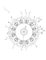
- FIG. 2 is a cross-sectional view showing an example of the overall configuration of the rotating electrical machine 1, and shows a cross-section taken along the line II-II in FIG.
- the rotating electrical machine 1 includes a stator 2, a rotor 3, a frame 4, a load side bracket 11, and an anti-load side bracket 13.
- the rotating electrical machine 1 is used as a motor or a generator.
- the rotor 3 includes a shaft 10, a rotor core 15 provided on the outer periphery of the shaft 10, and a plurality of permanent magnets (not shown) disposed on the rotor core 15.
- the rotor core 15 is configured by laminating a plurality of electromagnetic steel plates in the axial direction, and is disposed so as to face the stator 2 in the radial direction.
- the load side bracket 11 is fixed to the load side (right side in FIG. 1) of the frame 4, and the anti-load side bracket 13 is fixed to the anti-load side (left side in FIG. 1) of the frame 4.
- the shaft 10 is rotatably supported around the rotation axis AX by a load side bearing 12 provided on the load side bracket 11 and an antiload side bearing 14 provided on the antiload side bracket 13.
- the “load side” refers to the direction in which a load is attached to the rotating electrical machine 1, that is, the direction in which the shaft 10 protrudes (right side in FIG. 1) in this example. It points in the opposite direction to the load side (left side in FIG. 1).
- axial direction refers to the direction along the rotational axis AX of the shaft 10 (rotor 3)
- circumferential direction refers to the circumferential direction around the rotational axis AX
- diameter refers to a radial direction around the rotation axis AX.
- the stator 2 is provided on the inner peripheral surface of the frame 4 so as to face the rotor 3 in the radial direction.
- the stator 2 includes a stator core 5 provided on the inner peripheral surface of the frame 4, a bobbin 6 attached to the stator core 5, and a winding 7 wound around the bobbin 6.
- the bobbin 6 is made of an insulating material in order to electrically insulate the stator core 5 and the winding 7 from each other.
- the bobbin 6 may be a sheet-like insulator.
- the stator core 5 is configured by connecting a plurality (12 in the illustrated example) of divided cores 20 (also referred to as core pieces) in the circumferential direction.
- Each divided iron core 20 is configured by laminating a plurality of electromagnetic steel plates formed in a predetermined shape by, for example, press punching in the axial direction.
- the split iron core 20 includes a substantially arc-shaped yoke portion 21 and a teeth portion 22 provided integrally with the yoke portion 21.
- the teeth part 22 is provided with a main body part 22a provided so as to protrude radially inward from the yoke part 21, and a widened part 22b provided at the front end on the inner peripheral side of the main body part 22a and having an increased circumferential width. And have.
- the tips of adjacent widened portions 22b are separated in the circumferential direction, but may be in contact with each other.
- Each divided core 20 has a flat contact surface 24 at one end in the circumferential direction of the yoke portion 21, and a flat contact surface 26 that comes into contact with the contact surface 24 of the divided core 20 adjacent to the other end in the circumferential direction.
- the plurality of divided cores 20 are arranged in an annular shape so that the contact surface 24 of the other divided core 20 is in contact with the contact surface 26 of one of the divided cores 20 adjacent to each other in the circumferential direction. Thereby, the stator core 5 is comprised.
- Each of the split cores 20 is disposed in the circumferential direction after the bobbin 6 and the winding 7 are mounted on the tooth portion 22 to form the stator core 5. Then, after the stator core 5 is fixed to the inner peripheral surface of the frame 4 by press fitting or shrink fitting, it is molded with resin. As a result, as shown in FIG. 1, the stator core 5 (divided core 20), the bobbin 6, and the winding 7 are integrally fixed by a resin portion 17 made of resin. In order to reduce stress concentration on the slots 19 and the like when the stator core 5 is attached to the inner peripheral surface of the frame 4 by shrink fitting or the like, grooves 30 are formed along the axial direction on the outer peripheral surface of each divided core 20. Is provided.
- the windings 7 attached to the respective tooth portions 22 are accommodated in the slots 19 between the teeth portions 22 adjacent to each other in the circumferential direction, and opposite side portions of the winding layers of the windings 7. They are arranged with a gap 19a therebetween. Resin is press-fitted into the gap 19a during molding, and the resin portion 17 is filled.
- the resin portion 17 is not necessarily required, and the stator core 5 (the divided core 20), the bobbin 6, and the winding 7 may not be integrated with resin.
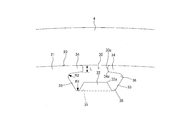
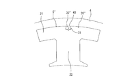
- Sectional shape of the groove of the split core An example of the cross-sectional shape (cross-sectional shape orthogonal to the axial direction) of the groove 30 of the split iron core 20 will be described with reference to FIGS. 3 and 4.
- the bobbin 6 and the resin 17 are not shown (the same applies to FIGS. 5 and 10 described later).
- the groove 30 is provided along the axial direction at a substantially central position in the circumferential direction of the outer peripheral surface of the split core 20.
- the groove 30 has an opening 30 a that opens on the inner peripheral surface of the frame 4.
- the split iron core 20 has a first protrusion 32 at the bottom 31 of the groove 30.
- the 1st protrusion part 32 protrudes in the substantially trapezoid shape toward the outer side of radial direction from the bottom part 31.
- the shape of the 1st protrusion part 32 is not restricted to trapezoid shape, For example, rectangular shape and circular arc shape may be sufficient.
- channel 30 has the two side surfaces 33 provided facing the circumferential direction. The two side surfaces 33 are provided so as to be inclined at a predetermined angle with respect to the radial direction so that the circumferential groove width decreases toward the inner side in the radial direction.
- the side surface 33 faces the end of the contact surfaces 24 and 26 on the slot side.
- the side surface 33 is provided such that a normal line n orthogonal to the side surface 33 passes through the vicinity of the radially inner end portions of the contact surfaces 24 and 26.
- the groove 30 has two second projecting portions 34 that are in contact with the inner peripheral surface of the frame 4.
- the two second projecting portions 34 are provided so as to project in a direction approaching each other from the radially outer end portions of the two side surfaces 33.
- the groove 30 has two acute-angled first notch portions 35 and two acute-angled second notch portions 36.
- the two first cutout portions 35 are provided between the first protrusion 32 and the two side surfaces 33, respectively.
- the second notch portions 36 are respectively provided between the two side surfaces 33 and the two second projecting portions 34.
- the first cutout portion 35 and the second cutout portion 36 have a cross-sectional shape perpendicular to the axial direction chamfered in an arc shape.
- the curvature radius R1 of the first notch 35 is smaller than the plate thickness t
- the second notch 36 The curvature radius R2 is set to be larger than the plate thickness t.
- the plate thickness t of the steel plate is 0.35 mm
- the curvature radius R1 of the first notch 35 is set to 0.3 mm
- the curvature radius R2 of the second notch 36 is set to 0.4 mm.
- the thickness L along the radial direction of the second protrusion 34 is, for example, at least twice the plate thickness t (0.7 mm or more in the above example) in consideration of the accuracy of the shape when punching the steel plate. Is set.
- the corners 32a on both sides in the circumferential direction of the first protrusion 32 and the radially outer and inner corners 34a of the tip of the second protrusion 34 are also chamfered in an arc shape with an appropriate curvature radius. It has become.
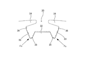
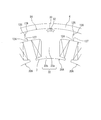
- the groove 30 receives and absorbs the compressive stress from each direction in the split iron core 20, but the compressive stress from the direction of the portion (corner portion 20a, corner portion 20b, corner portion 20c) where the compressive stress is particularly high. Fa, Fb, and Fc are efficiently received and absorbed, and the compressive stress generated in the split iron core 20 is relieved.
- the details of the relaxation action for each force of the groove 30 will be described.
- two compressive forces Fr from the frame 4 include two second protrusions 34 provided in contact with the inner peripheral surface of the frame 4 at the root portion. (A connection portion with the side surface 33.
- the second notch portion 36) serves as a fulcrum and bends inward in the radial direction according to the compression force Fr.
- frame 4 is relieve
- the 2nd notch part 36 provided between the side surface 33 and the 2nd protrusion part 34 acts as a spring which bends the 2nd protrusion part 34 with respect to the side surface 33.
- FIG. Thereby, the deflection of the second protruding portion 34 inward in the radial direction by the compression force Fr is promoted, and the effect of alleviating the variation in the compression force Fr is enhanced.
- the second notch portion 36 acts as a spring that bends the side surface 33 inward with respect to the second protrusion portion 34, and the first notch portion 35 is between the first protrusion portion 32 and the side surface 33. It acts as a spring that changes the angle and bends the first protrusion 32 outward. Thereby, the deflection of the two side surfaces 33 and the deflection of the first protrusion 32 due to the compressive stress Fc are promoted, and the absorption effect of the compressive stress Fc is enhanced.
- the 1st protrusion part 32 acts so that it may resist against those compressive stress. Thereby, it is possible to suppress the occurrence of local stress concentration at the bottom 31 of the groove 30 while relaxing the compressive stress generated in the split iron core 20 in the entire groove 30.
- the rotating electrical machine 1 of this embodiment is assembled as follows. After the bobbin 6 and the winding 7 are mounted on the tooth portion 22, the divided cores 20 are arranged so as to be connected in the circumferential direction to form the stator core 5. Then, the stator core 5 is fixed inside the frame 4 by press fitting or shrink fitting. Thereafter, the stator core 5 and the plurality of windings 7 and the like attached to the stator core 5 are integrated by the resin portion 17. In this way, the stator 2 is assembled.
- the load side bracket 11 on which the shaft 10 is installed is fixed to the load side of the frame 4 while the shaft 10 and the rotor 3 are inserted inside the stator 2.
- the anti-load side bracket 13 is fixed to the anti-load side of the frame 4 while pressing the shaft 10 into the anti-load side bearing 14.
- the rotating electrical machine 1 is assembled.
- the order in which the load side bracket 11 and the anti-load side bracket 13 are assembled may be opposite to the above.
- the bottom 31 is stretched particularly against the compressive stress Fb from the direction of the corner 20b and the compressive stress Fc from the direction of the corner 20c.
- the absorption effect is low. That is, the effect of relaxing the compressive stress generated in the split iron core 20 'is not sufficient.
- the second groove 40 is provided at the bottom 31 of the groove 30 ′′ of each split core 20 ′′.
- the stress concentration May interfere with the magnetic flux passing through the yoke portion 21.
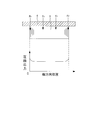
- the compressive force Fr compressive stress acting on the outer peripheral surface of the stator core 5 from the frame 4 increases in the vicinity of the end in the stacking direction (axial direction) of the stator core 5.
- the compressive force Fr when the compressive force Fr is large, the steel plate in the vicinity of the end in the stacking direction may bend outward in the axial direction due to local stress concentration at the position of the second groove 40, and may be peeled off from the split iron core 20 ′′. There is sex.
- the subject of the said comparative example 1 and the comparative example 2 can be solved. That is, in the present embodiment, the first protrusion 32 that protrudes outward in the radial direction is provided at the bottom 31 of the groove 30.
- the first protrusion 32 acts to stretch when the groove 30 receives compressive stress Fa, Fb, Fc, etc. from both sides in the circumferential direction, and local stress concentration is generated at the bottom 31 as in the second comparative example. Generation
- production can be suppressed.
- a recess (first notch 35) is formed between the first protrusion 32 and the side surface 33, and a groove is formed by the recess.
- the groove 30 has two side surfaces 33 provided facing each other in the circumferential direction so that the groove width in the circumferential direction decreases toward the inside in the radial direction.
- the side surface 33 of the groove 30 can be directed to the slot 9 side of the contact surfaces 24 and 26.
- the two side surfaces 33 can receive and absorb the compressive stress Fb particularly from the direction of the corner 20b on the slot 9 side of the contact surfaces 24 and 26.
- the groove 30 is in contact with the inner peripheral surface of the frame 4, and is provided with two second protrusions that protrude from the radially outer ends of the two side surfaces 33 toward each other.
- a protrusion 34 is provided.
- the two second projecting portions 34 can bend according to the compressive force Fr from the frame 4 with the root portion (connecting portion with the side surface 33) as a fulcrum.
- variation in the compression force Fr from the frame 4 can be alleviated, and uneven compression stress, strain, and the like can be suppressed from occurring in the split iron core 20.
- the width of the opening 30 a is narrowed by the second protrusion 34, and the contact area between the inner peripheral surface of the frame 4 and the outer peripheral surface of the split iron core 20 is increased as compared with the first and second comparative examples. be able to. Thereby, since the heat conduction area used as the main path for radiating the heat
- the groove 30 includes two acute-angled first cutout portions 35 provided between the first protrusion 32 and the two side surfaces 33, respectively.
- the first notch 35 changes the angle between the first protrusion 32 and the side surface 33 according to the compressive stress acting on the groove 30 (the side 33 is bent with respect to the first protrusion 32). Acts as a spring. Thereby, the compressive stress Fa, Fb, Fc which acts on the groove
- the compressive forces acting on the contact surfaces 24 and 26 at both ends of the divided core 20 are different due to variations in the inner diameter and thickness of the frame 4, variations in the outer diameter of the divided core 20, and the like.
- the first notch portions 35 are provided on both sides in the circumferential direction of the first protrusion 32, different compressive stresses acting from both sides in the circumferential direction can be absorbed according to the size. Thereby, even when local stress concentration occurs in the divided core 20, it is possible to prevent the concentrated stress from being dispersed and spread over the whole of the plurality of divided cores 20 arranged in an annular shape in the circumferential direction. As a result, the compressive stress in each divided iron core 20 can be equalized.
- the groove 30 includes two acute-angled second notches 36 provided between the two side surfaces 33 and the two second protrusions 34, respectively.
- the second notch 36 changes the angle between the second protrusion 34 and the side surface 33 according to the compressive force Fr acting on the second protrusion 34 from the frame 4 (the second protrusion 34 is changed). Acts as a spring). Thereby, the effect which relieves the dispersion
- the split core 20 is configured by laminating a plurality of steel plates, and the first cutout portion 35 and the second cutout portion 36 have a circular cross-sectional shape orthogonal to the axial direction. It is an arc chamfered shape, the radius of curvature R1 of the first notch 35 is smaller than the plate thickness t of the steel plate, and the radius of curvature R2 of the second notch 36 is larger than the plate thickness t of the steel plate. .
- the spring action by the first notch 35 can be made higher than the spring action by the second notch 36.
- the shape of the groove 30 can be made an optimum shape for absorbing the compressive stress depending on the magnitude of the compressive stress acting from each direction, and the absorption effect can be enhanced.
- the split iron core 20 has contact surfaces 24 and 26 that come into contact with the adjacent split iron cores 20 at both end portions in the circumferential direction, and the side surface 33 is formed on the side surface 33.
- An orthogonal normal line n is provided so as to pass in the vicinity of the radially inner end portions of the contact surfaces 24 and 26.
- the side surface 33 of the groove 30 can be directed to the end portion of the contact surfaces 24 and 26 on the slot side. Therefore, among the compressive stress acting on the groove 30, the corner portion 20b on the slot side of the contact surfaces 24 and 26 in particular. The effect of absorbing the compressive stress Fb from the direction can be enhanced.
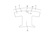
- each of the split iron cores has a protrusion on the contact surface at one end in the circumferential direction, and the recess that engages the protrusion of the adjacent split core on the contact surface at the other end in the circumferential direction. You may have. An example of this modification is shown in FIG.
- the split core 20A of the present modification has a protruding portion 125 on the contact surface 124 on one end in the circumferential direction, and on the contact surface 126 on the other end in the circumferential direction. It has the recessed part 127 fitted to the protrusion part 125 of 20 A of adjacent division
- the projecting portion 125 has a tapered shape (in this example, a trapezoidal shape or a triangular shape) whose cross-sectional shape (cross-sectional shape orthogonal to the axial direction) decreases in radial direction toward the tip on one side in the circumferential direction. .
- the concave portion 127 has a cross-sectional shape corresponding to the protruding portion 125, that is, a shape in which the opening width in the radial direction becomes smaller toward the tip on one side in the circumferential direction.
- the stator core 5A is configured by fitting the protrusions 125 of the other split core 20A into the recesses 127 of one split core 20A of the split cores 20A adjacent in the circumferential direction and connecting them to each other in the circumferential direction.
Landscapes
- Engineering & Computer Science (AREA)
- Power Engineering (AREA)
- Iron Core Of Rotating Electric Machines (AREA)
- Manufacturing & Machinery (AREA)
Abstract
Description
図1及び図2を用いて、本実施形態に係る回転電機1の全体構成の一例について説明する。図1は回転電機1の全体構成の一例を表す軸方向断面図である。図2は回転電機1の全体構成の一例を表す横断面図であり、図1のII-II断面における横断面を示す。
図3及び図4を用いて、分割鉄心20の溝30の断面形状(軸方向に直交する断面形状)の一例について説明する。なお、図3ではボビン6及び樹脂17等の図示を省略している(後述の図5、図10も同様)。
図5及び図6A~図6Dを用いて、溝30による分割鉄心20の圧縮応力の緩和作用の一例について説明する。なお、図5のハッチングで示す領域は、圧縮応力が比較的高い領域(所定の値より高い領域)を示している。
通常、回転電機1では、フレーム4の内径や肉厚のばらつき、分割鉄心20の外径のばらつき等に起因して、フレーム4から固定子鉄心5の外周面に作用する圧縮力Frにはばらつきが生じる。この圧縮力Frのばらつきは、分割鉄心20に不均等な圧縮応力やひずみ等を生じさせ、鉄損の増加の一因となる。
図6Bに点線で示すように、溝30に各方向から作用する圧縮応力のうち、特に接触面24,26のフレーム4側の角部20aの方向からの圧縮応力Faに対しては、2つの第2突出部34及び2つの側面33が、第1切欠き部35を支点として溝30の内側にたわむことで、圧縮応力Faを効果的に吸収する。この際、第1突出部32と2つの側面33との間に設けられた2つの第1切欠き部35は、第1突出部32に対して側面33をたわませるばねとして作用する。これにより、圧縮応力Faによる第2突出部34及び側面33のたわみが助長され、圧縮応力Faを緩和する効果が高められる。
図6Cに点線で示すように、溝30に各方向から作用する圧縮応力のうち、特に接触面24,26のスロット9側の角部20bの方向からの圧縮応力Fbに対しては、上記圧縮応力Faと同様に、2つの第2突出部34及び2つの側面33が、第1切欠き部35を支点として溝30の内側にたわむことで、圧縮応力Fbを効果的に吸収する。この際、上述したように、側面33の法線nが接触面24,26のスロット側端部近傍を通るように設定されており、2つの側面33の向きが圧縮応力Fbに対して略直角となるので、側面33による圧縮応力Fbの吸収効果が特に高められる。
図6Dに点線で示すように、溝30に各方向から作用する圧縮応力のうち、特にヨーク部21とティース部22の間の隅部20cの方向からの圧縮応力Fcに対しては、2つの側面33が圧縮応力Fc受けて溝30の内側にたわむとともに、第1突出部32が圧縮応力Fcを受けて径方向外側に移動するようにたわむことで、圧縮応力Fcを効果的に吸収する。この際、第2切欠き部36が第2突出部34に対し側面33を内側にたわませるばねとして作用すると共に、第1切欠き部35が第1突出部32と側面33との間の角度を変動させて第1突出部32を外側にたわませるばねとして作用する。これにより、圧縮応力Fcによる2つの側面33のたわみ及び第1突出部32のたわみが助長され、圧縮応力Fcの吸収効果が高められる。
本実施形態の回転電機1は、概略次のようにして組み立てられる。各分割鉄心20は、ティース部22にボビン6及び巻線7が装着された後、周方向に接続するように配置されて固定子鉄心5が形成される。そして、当該固定子鉄心5がフレーム4の内側に圧入又は焼きばめ等により固定される。その後、固定子鉄心5と固定子鉄心5に装着された複数の巻線7等とが樹脂部17で一体化される。このようにして、固定子2が組み立てられる。
以上説明した本実施形態による効果を説明する前に、比較例の溝形状及び課題の一例について説明する。
本実施形態によれば、上記比較例1及び比較例2の課題点を解決できる。すなわち、本実施形態では、溝30の底部31に径方向の外側に向けて突出した第1突出部32が設けられている。この第1突出部32は、溝30が周方向両側から圧縮応力Fa,Fb,Fc等を受けた場合に突っ張るように作用し、上記比較例2のように底部31に局部的な応力集中が発生するのを抑制できる。その一方で、底部31に第1突出部32が設けられる結果、当該第1突出部32と側面33との間に凹部(第1切欠き部35)が形成されることとなり、その凹部による溝30のたわみにより、上記比較例1に比べて圧縮応力Fb,Fc等に対する吸収効果を高めることが可能である。以上により、溝30全体において分割鉄心20に生じる圧縮応力を緩和しつつ、局部的な応力集中が発生するのを抑制することができる。その結果、ヨーク部21を通る磁束への影響を低減できると共に、積層方向端部近傍の鋼板の剥離を防止できる。
なお、開示の実施形態は、上記に限られるものではなく、その趣旨及び技術的思想を逸脱しない範囲内で種々の変形が可能である。
4 フレーム
5 固定子鉄心
20 分割鉄心
20b 角部(内側端部)
24 接触面
26 接触面
30 溝
31 底部
32 第1突出部
33 側面
34 第2突出部
35 第1切欠き部
36 第2切欠き部
n 法線
R1 曲率半径
R2 曲率半径
t 板厚
Claims (8)
- フレームと、
前記フレームの内周面に固定され、周方向に配置された複数の分割鉄心を備えた固定子鉄心と、
前記分割鉄心の外周面における前記周方向の中心位置に軸方向に設けられた溝と、
前記溝の底部に設けられた、径方向の外側に向けて突出した第1突出部と、
を有することを特徴とする回転電機。 - 前記溝は、
前記径方向の内側に向けて前記周方向の溝幅が減少するように、前記周方向に対向して設けられた2つの側面を有する
ことを特徴とする請求項1に記載の回転電機。 - 前記溝は、
前記フレームの前記内周面に接触し、前記2つの側面の各々における前記径方向の外側端部から互いに近づく方向に突出して設けられた、2つの第2突出部を有する
ことを特徴とする請求項2に記載の回転電機。 - 前記溝は、
前記第1突出部と前記2つの側面との間にそれぞれ設けられた、2つの鋭角状の第1切欠き部を有する
ことを特徴とする請求項3に記載の回転電機。 - 前記溝は、
前記2つの側面と前記2つの第2突出部との間にそれぞれ設けられた、2つの鋭角状の第2切欠き部を有する
ことを特徴とする請求項4に記載の回転電機。 - 前記分割鉄心は、
複数の鋼板が積層されて構成されており、
前記第1切欠き部及び前記第2切欠き部は、
前記軸方向に直交する前記断面形状が、円弧状に面取りされた形状であり、
前記第1切欠き部の曲率半径は、前記鋼板の板厚よりも小さく、
前記第2切欠き部の曲率半径は、前記鋼板の板厚よりも大きい
ことを特徴とする請求項5に記載の回転電機。 - 前記分割鉄心は、
前記周方向における両側の端部に、隣接する前記分割鉄心と接触する接触面をそれぞれ有しており、
前記側面は、
当該側面に直交する法線が前記接触面における前記径方向の内側端部近傍を通るように設けられている
ことを特徴とする請求項2乃至6のいずれか1項に記載の回転電機。 - 複数の分割鉄心を備えた固定子鉄心と、
前記分割鉄心の外周面に軸方向に設けられた溝と、
前記溝の底部に設けられた、径方向の外側に向けて突出した第1突出部と、を有する回転電機の製造方法であって、
前記複数の分割鉄心を前記周方向に接続するように配置して前記固定子鉄心を形成することと、
前記固定子鉄心の外側にフレームを焼きばめにより固定することと、
を有することを特徴とする回転電機の製造方法。
Priority Applications (5)
| Application Number | Priority Date | Filing Date | Title |
|---|---|---|---|
| JP2018502867A JP6593731B2 (ja) | 2016-02-29 | 2016-02-29 | 回転電機及び回転電機の製造方法 |
| PCT/JP2016/056032 WO2017149593A1 (ja) | 2016-02-29 | 2016-02-29 | 回転電機及び回転電機の製造方法 |
| EP16892438.9A EP3425770B1 (en) | 2016-02-29 | 2016-02-29 | Rotating electric machine and rotating electric machine manufacturing method |
| CN201680082757.7A CN108702043B (zh) | 2016-02-29 | 2016-02-29 | 旋转电机和旋转电机的制造方法 |
| US16/052,620 US10855120B2 (en) | 2016-02-29 | 2018-08-02 | Rotating electrical machine and producing method of rotating electrical machine |
Applications Claiming Priority (1)
| Application Number | Priority Date | Filing Date | Title |
|---|---|---|---|
| PCT/JP2016/056032 WO2017149593A1 (ja) | 2016-02-29 | 2016-02-29 | 回転電機及び回転電機の製造方法 |
Related Child Applications (1)
| Application Number | Title | Priority Date | Filing Date |
|---|---|---|---|
| US16/052,620 Continuation US10855120B2 (en) | 2016-02-29 | 2018-08-02 | Rotating electrical machine and producing method of rotating electrical machine |
Publications (1)
| Publication Number | Publication Date |
|---|---|
| WO2017149593A1 true WO2017149593A1 (ja) | 2017-09-08 |
Family
ID=59742610
Family Applications (1)
| Application Number | Title | Priority Date | Filing Date |
|---|---|---|---|
| PCT/JP2016/056032 Ceased WO2017149593A1 (ja) | 2016-02-29 | 2016-02-29 | 回転電機及び回転電機の製造方法 |
Country Status (5)
| Country | Link |
|---|---|
| US (1) | US10855120B2 (ja) |
| EP (1) | EP3425770B1 (ja) |
| JP (1) | JP6593731B2 (ja) |
| CN (1) | CN108702043B (ja) |
| WO (1) | WO2017149593A1 (ja) |
Cited By (3)
| Publication number | Priority date | Publication date | Assignee | Title |
|---|---|---|---|---|
| KR102031852B1 (ko) * | 2018-05-08 | 2019-10-14 | 엘지전자 주식회사 | 전동식 압축기 |
| US20200014256A1 (en) * | 2017-02-10 | 2020-01-09 | Mitsui High-Tec, Inc. | Annular core piece and annular core |
| JP2023023370A (ja) * | 2021-08-05 | 2023-02-16 | 日本製鉄株式会社 | 分割型固定子および回転電機 |
Families Citing this family (2)
| Publication number | Priority date | Publication date | Assignee | Title |
|---|---|---|---|---|
| JP6714118B1 (ja) * | 2019-02-18 | 2020-06-24 | 三菱電機株式会社 | 回転電機のステータ |
| FR3121555A1 (fr) * | 2021-04-06 | 2022-10-07 | Inteva Products, Llc. | Stator pour moteur ou générateur sans balais |
Citations (4)
| Publication number | Priority date | Publication date | Assignee | Title |
|---|---|---|---|---|
| JP2005051941A (ja) * | 2003-07-30 | 2005-02-24 | Toyota Motor Corp | 分割ステータコア |
| JP2005110464A (ja) * | 2003-10-02 | 2005-04-21 | Mitsubishi Electric Corp | 電動機のステータコア及びその製造方法 |
| JP2009136101A (ja) * | 2007-11-30 | 2009-06-18 | Mitsubishi Electric Corp | モータ及びそれを備えた冷媒圧縮機 |
| US20100213788A1 (en) * | 2009-02-26 | 2010-08-26 | Richard Guttenberger | Stator for an electronically commutated dc motor |
Family Cites Families (9)
| Publication number | Priority date | Publication date | Assignee | Title |
|---|---|---|---|---|
| US6487769B2 (en) * | 2000-11-30 | 2002-12-03 | Emerson Electric Co. | Method and apparatus for constructing a segmented stator |
| US7012350B2 (en) * | 2001-01-04 | 2006-03-14 | Emerson Electric Co. | Segmented stator switched reluctance machine |
| DE102005051506B4 (de) * | 2005-10-26 | 2025-03-13 | Sew-Eurodrive Gmbh & Co Kg | Elektromotor und Verfahren zum Herstellen eines Elektromotors |
| CN200980000Y (zh) * | 2006-11-13 | 2007-11-21 | 广东威灵电机制造有限公司 | 一种用于电动机的定子铁心 |
| JP4623217B2 (ja) * | 2008-08-06 | 2011-02-02 | 株式会社デンソー | 燃料供給ポンプ |
| EP2680400A1 (en) * | 2011-02-21 | 2014-01-01 | Mitsubishi Electric Corporation | Unit core of rotating electrical machine |
| WO2014128938A1 (ja) * | 2013-02-22 | 2014-08-28 | 三菱電機株式会社 | 永久磁石埋込型電動機、圧縮機、および冷凍空調装置 |
| WO2015063871A1 (ja) * | 2013-10-29 | 2015-05-07 | 三菱電機株式会社 | 永久磁石埋込型電動機、圧縮機、および冷凍空調装置 |
| CN104600880A (zh) * | 2013-10-30 | 2015-05-06 | 河南超微电动汽车有限公司 | 定子分体交流伺服电机 |
-
2016
- 2016-02-29 WO PCT/JP2016/056032 patent/WO2017149593A1/ja not_active Ceased
- 2016-02-29 CN CN201680082757.7A patent/CN108702043B/zh active Active
- 2016-02-29 JP JP2018502867A patent/JP6593731B2/ja active Active
- 2016-02-29 EP EP16892438.9A patent/EP3425770B1/en active Active
-
2018
- 2018-08-02 US US16/052,620 patent/US10855120B2/en active Active
Patent Citations (4)
| Publication number | Priority date | Publication date | Assignee | Title |
|---|---|---|---|---|
| JP2005051941A (ja) * | 2003-07-30 | 2005-02-24 | Toyota Motor Corp | 分割ステータコア |
| JP2005110464A (ja) * | 2003-10-02 | 2005-04-21 | Mitsubishi Electric Corp | 電動機のステータコア及びその製造方法 |
| JP2009136101A (ja) * | 2007-11-30 | 2009-06-18 | Mitsubishi Electric Corp | モータ及びそれを備えた冷媒圧縮機 |
| US20100213788A1 (en) * | 2009-02-26 | 2010-08-26 | Richard Guttenberger | Stator for an electronically commutated dc motor |
Non-Patent Citations (1)
| Title |
|---|
| See also references of EP3425770A4 * |
Cited By (5)
| Publication number | Priority date | Publication date | Assignee | Title |
|---|---|---|---|---|
| US20200014256A1 (en) * | 2017-02-10 | 2020-01-09 | Mitsui High-Tec, Inc. | Annular core piece and annular core |
| US11605990B2 (en) * | 2017-02-10 | 2023-03-14 | Mitsui High-Tec, Inc. | Annular core piece and annular core |
| KR102031852B1 (ko) * | 2018-05-08 | 2019-10-14 | 엘지전자 주식회사 | 전동식 압축기 |
| JP2023023370A (ja) * | 2021-08-05 | 2023-02-16 | 日本製鉄株式会社 | 分割型固定子および回転電機 |
| JP7799162B2 (ja) | 2021-08-05 | 2026-01-15 | 日本製鉄株式会社 | 分割型固定子および回転電機 |
Also Published As
| Publication number | Publication date |
|---|---|
| JP6593731B2 (ja) | 2019-10-23 |
| EP3425770A1 (en) | 2019-01-09 |
| EP3425770A4 (en) | 2019-09-11 |
| EP3425770B1 (en) | 2021-01-13 |
| CN108702043B (zh) | 2021-02-02 |
| CN108702043A (zh) | 2018-10-23 |
| US10855120B2 (en) | 2020-12-01 |
| JPWO2017149593A1 (ja) | 2018-10-18 |
| US20180342913A1 (en) | 2018-11-29 |
Similar Documents
| Publication | Publication Date | Title |
|---|---|---|
| JP6593731B2 (ja) | 回転電機及び回転電機の製造方法 | |
| JP5740436B2 (ja) | 回転電機のステータコア | |
| US9793774B2 (en) | Armature for rotary electric machine | |
| US9735636B2 (en) | Rotor and dynamo-electric machine having the same | |
| JP6621058B2 (ja) | 回転電機及び回転電機の製造方法 | |
| JP5326642B2 (ja) | 回転電機及び回転電機の製造方法 | |
| JPWO2017141361A1 (ja) | 回転電機及び回転電機の製造方法 | |
| CN107408852A (zh) | 转子、旋转电机以及转子的制造方法 | |
| KR20140002508A (ko) | 영구 자석 모터 | |
| WO2017061305A1 (ja) | 回転子および回転電機 | |
| JP2012065510A (ja) | ステータ | |
| WO2017159811A1 (ja) | 回転電機及び回転電機の製造方法 | |
| JP2006296010A (ja) | 密閉型圧縮機 | |
| JP2014003881A (ja) | 回転電機のステータ | |
| JP6416417B2 (ja) | 回転電機の固定子、回転電機、および回転電機の固定子の製造方法 | |
| JP2014003785A (ja) | 永久磁石式回転電機 | |
| JP7561719B2 (ja) | ステータ、及び、回転電機 | |
| WO2020067349A1 (ja) | 回転電機のロータ | |
| JP2017046369A (ja) | 電機子、電機子の製造方法および回転電機 | |
| KR20150000944A (ko) | 전동기용 스테이터 조립체 | |
| JP7774714B2 (ja) | インシュレータ、ステータ、回転電機、および、ステータの製造方法 | |
| JP5729090B2 (ja) | ロータ及び回転電気機械 | |
| KR101668182B1 (ko) | 모터의 회전자 조립 방법 | |
| KR20230100112A (ko) | 모터 | |
| JP2006311704A (ja) | アキシャルギャップ型回転電機のステータ構造 |
Legal Events
| Date | Code | Title | Description |
|---|---|---|---|
| ENP | Entry into the national phase |
Ref document number: 2018502867 Country of ref document: JP Kind code of ref document: A |
|
| NENP | Non-entry into the national phase |
Ref country code: DE |
|
| WWE | Wipo information: entry into national phase |
Ref document number: 2016892438 Country of ref document: EP |
|
| ENP | Entry into the national phase |
Ref document number: 2016892438 Country of ref document: EP Effective date: 20181001 |
|
| 121 | Ep: the epo has been informed by wipo that ep was designated in this application |
Ref document number: 16892438 Country of ref document: EP Kind code of ref document: A1 |