WO2017149596A1 - レーダ装置 - Google Patents
レーダ装置 Download PDFInfo
- Publication number
- WO2017149596A1 WO2017149596A1 PCT/JP2016/056045 JP2016056045W WO2017149596A1 WO 2017149596 A1 WO2017149596 A1 WO 2017149596A1 JP 2016056045 W JP2016056045 W JP 2016056045W WO 2017149596 A1 WO2017149596 A1 WO 2017149596A1
- Authority
- WO
- WIPO (PCT)
- Prior art keywords
- signal
- transmission
- frequency
- target
- unit
- Prior art date
- Legal status (The legal status is an assumption and is not a legal conclusion. Google has not performed a legal analysis and makes no representation as to the accuracy of the status listed.)
- Ceased
Links
Images









Classifications
-
- G—PHYSICS
- G01—MEASURING; TESTING
- G01S—RADIO DIRECTION-FINDING; RADIO NAVIGATION; DETERMINING DISTANCE OR VELOCITY BY USE OF RADIO WAVES; LOCATING OR PRESENCE-DETECTING BY USE OF THE REFLECTION OR RERADIATION OF RADIO WAVES; ANALOGOUS ARRANGEMENTS USING OTHER WAVES
- G01S13/00—Systems using the reflection or reradiation of radio waves, e.g. radar systems; Analogous systems using reflection or reradiation of waves whose nature or wavelength is irrelevant or unspecified
- G01S13/02—Systems using reflection of radio waves, e.g. primary radar systems; Analogous systems
- G01S13/06—Systems determining position data of a target
- G01S13/08—Systems for measuring distance only
- G01S13/10—Systems for measuring distance only using transmission of interrupted, pulse modulated waves
- G01S13/26—Systems for measuring distance only using transmission of interrupted, pulse modulated waves wherein the transmitted pulses use a frequency- or phase-modulated carrier wave
- G01S13/28—Systems for measuring distance only using transmission of interrupted, pulse modulated waves wherein the transmitted pulses use a frequency- or phase-modulated carrier wave with time compression of received pulses
- G01S13/282—Systems for measuring distance only using transmission of interrupted, pulse modulated waves wherein the transmitted pulses use a frequency- or phase-modulated carrier wave with time compression of received pulses using a frequency modulated carrier wave
-
- G—PHYSICS
- G01—MEASURING; TESTING
- G01S—RADIO DIRECTION-FINDING; RADIO NAVIGATION; DETERMINING DISTANCE OR VELOCITY BY USE OF RADIO WAVES; LOCATING OR PRESENCE-DETECTING BY USE OF THE REFLECTION OR RERADIATION OF RADIO WAVES; ANALOGOUS ARRANGEMENTS USING OTHER WAVES
- G01S13/00—Systems using the reflection or reradiation of radio waves, e.g. radar systems; Analogous systems using reflection or reradiation of waves whose nature or wavelength is irrelevant or unspecified
- G01S13/02—Systems using reflection of radio waves, e.g. primary radar systems; Analogous systems
- G01S13/06—Systems determining position data of a target
- G01S13/42—Simultaneous measurement of distance and other co-ordinates
- G01S13/44—Monopulse radar, i.e. simultaneous lobing
- G01S13/449—Combined with MTI or Doppler processing circuits
-
- G—PHYSICS
- G01—MEASURING; TESTING
- G01S—RADIO DIRECTION-FINDING; RADIO NAVIGATION; DETERMINING DISTANCE OR VELOCITY BY USE OF RADIO WAVES; LOCATING OR PRESENCE-DETECTING BY USE OF THE REFLECTION OR RERADIATION OF RADIO WAVES; ANALOGOUS ARRANGEMENTS USING OTHER WAVES
- G01S13/00—Systems using the reflection or reradiation of radio waves, e.g. radar systems; Analogous systems using reflection or reradiation of waves whose nature or wavelength is irrelevant or unspecified
- G01S13/003—Bistatic radar systems; Multistatic radar systems
-
- G—PHYSICS
- G01—MEASURING; TESTING
- G01S—RADIO DIRECTION-FINDING; RADIO NAVIGATION; DETERMINING DISTANCE OR VELOCITY BY USE OF RADIO WAVES; LOCATING OR PRESENCE-DETECTING BY USE OF THE REFLECTION OR RERADIATION OF RADIO WAVES; ANALOGOUS ARRANGEMENTS USING OTHER WAVES
- G01S13/00—Systems using the reflection or reradiation of radio waves, e.g. radar systems; Analogous systems using reflection or reradiation of waves whose nature or wavelength is irrelevant or unspecified
- G01S13/02—Systems using reflection of radio waves, e.g. primary radar systems; Analogous systems
- G01S13/50—Systems of measurement based on relative movement of target
- G01S13/52—Discriminating between fixed and moving objects or between objects moving at different speeds
- G01S13/522—Discriminating between fixed and moving objects or between objects moving at different speeds using transmissions of interrupted pulse modulated waves
- G01S13/524—Discriminating between fixed and moving objects or between objects moving at different speeds using transmissions of interrupted pulse modulated waves based upon the phase or frequency shift resulting from movement of objects, with reference to the transmitted signals, e.g. coherent MTi
-
- G—PHYSICS
- G01—MEASURING; TESTING
- G01S—RADIO DIRECTION-FINDING; RADIO NAVIGATION; DETERMINING DISTANCE OR VELOCITY BY USE OF RADIO WAVES; LOCATING OR PRESENCE-DETECTING BY USE OF THE REFLECTION OR RERADIATION OF RADIO WAVES; ANALOGOUS ARRANGEMENTS USING OTHER WAVES
- G01S13/00—Systems using the reflection or reradiation of radio waves, e.g. radar systems; Analogous systems using reflection or reradiation of waves whose nature or wavelength is irrelevant or unspecified
- G01S13/02—Systems using reflection of radio waves, e.g. primary radar systems; Analogous systems
- G01S13/50—Systems of measurement based on relative movement of target
- G01S13/58—Velocity or trajectory determination systems; Sense-of-movement determination systems
- G01S13/581—Velocity or trajectory determination systems; Sense-of-movement determination systems using transmission of interrupted pulse modulated waves and based upon the Doppler effect resulting from movement of targets
- G01S13/582—Velocity or trajectory determination systems; Sense-of-movement determination systems using transmission of interrupted pulse modulated waves and based upon the Doppler effect resulting from movement of targets adapted for simultaneous range and velocity measurements
-
- G—PHYSICS
- G01—MEASURING; TESTING
- G01S—RADIO DIRECTION-FINDING; RADIO NAVIGATION; DETERMINING DISTANCE OR VELOCITY BY USE OF RADIO WAVES; LOCATING OR PRESENCE-DETECTING BY USE OF THE REFLECTION OR RERADIATION OF RADIO WAVES; ANALOGOUS ARRANGEMENTS USING OTHER WAVES
- G01S7/00—Details of systems according to groups G01S13/00, G01S15/00, G01S17/00
- G01S7/02—Details of systems according to groups G01S13/00, G01S15/00, G01S17/00 of systems according to group G01S13/00
- G01S7/023—Interference mitigation, e.g. reducing or avoiding non-intentional interference with other HF-transmitters, base station transmitters for mobile communication or other radar systems, e.g. using electro-magnetic interference [EMI] reduction techniques
- G01S7/0232—Avoidance by frequency multiplex
-
- G—PHYSICS
- G01—MEASURING; TESTING
- G01S—RADIO DIRECTION-FINDING; RADIO NAVIGATION; DETERMINING DISTANCE OR VELOCITY BY USE OF RADIO WAVES; LOCATING OR PRESENCE-DETECTING BY USE OF THE REFLECTION OR RERADIATION OF RADIO WAVES; ANALOGOUS ARRANGEMENTS USING OTHER WAVES
- G01S7/00—Details of systems according to groups G01S13/00, G01S15/00, G01S17/00
- G01S7/02—Details of systems according to groups G01S13/00, G01S15/00, G01S17/00 of systems according to group G01S13/00
- G01S7/28—Details of pulse systems
- G01S7/285—Receivers
- G01S7/292—Extracting wanted echo-signals
- G01S7/2923—Extracting wanted echo-signals based on data belonging to a number of consecutive radar periods
- G01S7/2926—Extracting wanted echo-signals based on data belonging to a number of consecutive radar periods by integration
-
- G—PHYSICS
- G01—MEASURING; TESTING
- G01S—RADIO DIRECTION-FINDING; RADIO NAVIGATION; DETERMINING DISTANCE OR VELOCITY BY USE OF RADIO WAVES; LOCATING OR PRESENCE-DETECTING BY USE OF THE REFLECTION OR RERADIATION OF RADIO WAVES; ANALOGOUS ARRANGEMENTS USING OTHER WAVES
- G01S7/00—Details of systems according to groups G01S13/00, G01S15/00, G01S17/00
- G01S7/02—Details of systems according to groups G01S13/00, G01S15/00, G01S17/00 of systems according to group G01S13/00
- G01S7/28—Details of pulse systems
- G01S7/285—Receivers
- G01S7/295—Means for transforming co-ordinates or for evaluating data, e.g. using computers
-
- G—PHYSICS
- G01—MEASURING; TESTING
- G01S—RADIO DIRECTION-FINDING; RADIO NAVIGATION; DETERMINING DISTANCE OR VELOCITY BY USE OF RADIO WAVES; LOCATING OR PRESENCE-DETECTING BY USE OF THE REFLECTION OR RERADIATION OF RADIO WAVES; ANALOGOUS ARRANGEMENTS USING OTHER WAVES
- G01S13/00—Systems using the reflection or reradiation of radio waves, e.g. radar systems; Analogous systems using reflection or reradiation of waves whose nature or wavelength is irrelevant or unspecified
- G01S13/02—Systems using reflection of radio waves, e.g. primary radar systems; Analogous systems
- G01S13/50—Systems of measurement based on relative movement of target
-
- G—PHYSICS
- G01—MEASURING; TESTING
- G01S—RADIO DIRECTION-FINDING; RADIO NAVIGATION; DETERMINING DISTANCE OR VELOCITY BY USE OF RADIO WAVES; LOCATING OR PRESENCE-DETECTING BY USE OF THE REFLECTION OR RERADIATION OF RADIO WAVES; ANALOGOUS ARRANGEMENTS USING OTHER WAVES
- G01S13/00—Systems using the reflection or reradiation of radio waves, e.g. radar systems; Analogous systems using reflection or reradiation of waves whose nature or wavelength is irrelevant or unspecified
- G01S13/02—Systems using reflection of radio waves, e.g. primary radar systems; Analogous systems
- G01S13/50—Systems of measurement based on relative movement of target
- G01S13/52—Discriminating between fixed and moving objects or between objects moving at different speeds
- G01S13/522—Discriminating between fixed and moving objects or between objects moving at different speeds using transmissions of interrupted pulse modulated waves
-
- G—PHYSICS
- G01—MEASURING; TESTING
- G01S—RADIO DIRECTION-FINDING; RADIO NAVIGATION; DETERMINING DISTANCE OR VELOCITY BY USE OF RADIO WAVES; LOCATING OR PRESENCE-DETECTING BY USE OF THE REFLECTION OR RERADIATION OF RADIO WAVES; ANALOGOUS ARRANGEMENTS USING OTHER WAVES
- G01S13/00—Systems using the reflection or reradiation of radio waves, e.g. radar systems; Analogous systems using reflection or reradiation of waves whose nature or wavelength is irrelevant or unspecified
- G01S13/87—Combinations of radar systems, e.g. primary radar and secondary radar
-
- G—PHYSICS
- G01—MEASURING; TESTING
- G01S—RADIO DIRECTION-FINDING; RADIO NAVIGATION; DETERMINING DISTANCE OR VELOCITY BY USE OF RADIO WAVES; LOCATING OR PRESENCE-DETECTING BY USE OF THE REFLECTION OR RERADIATION OF RADIO WAVES; ANALOGOUS ARRANGEMENTS USING OTHER WAVES
- G01S13/00—Systems using the reflection or reradiation of radio waves, e.g. radar systems; Analogous systems using reflection or reradiation of waves whose nature or wavelength is irrelevant or unspecified
- G01S13/88—Radar or analogous systems specially adapted for specific applications
- G01S13/93—Radar or analogous systems specially adapted for specific applications for anti-collision purposes
- G01S13/931—Radar or analogous systems specially adapted for specific applications for anti-collision purposes of land vehicles
-
- G—PHYSICS
- G01—MEASURING; TESTING
- G01S—RADIO DIRECTION-FINDING; RADIO NAVIGATION; DETERMINING DISTANCE OR VELOCITY BY USE OF RADIO WAVES; LOCATING OR PRESENCE-DETECTING BY USE OF THE REFLECTION OR RERADIATION OF RADIO WAVES; ANALOGOUS ARRANGEMENTS USING OTHER WAVES
- G01S7/00—Details of systems according to groups G01S13/00, G01S15/00, G01S17/00
- G01S7/02—Details of systems according to groups G01S13/00, G01S15/00, G01S17/00 of systems according to group G01S13/00
- G01S7/28—Details of pulse systems
- G01S7/285—Receivers
- G01S7/288—Coherent receivers
- G01S7/2883—Coherent receivers using FFT processing
Definitions
- the present invention includes a plurality of transmission radars that transmit signals having a transmission frequency changed at predetermined intervals, and a reception radar that receives a signal reflected by a target, and performs target detection and distance measurement by processing the received signal.
- the present invention also relates to a radar apparatus that performs speed measurement and angle measurement.
- Non-Patent Document 1 different transmission radars transmit transmission signals of transmission frequencies that are frequency-modulated in the ascending order within the pulse at different center frequencies, and reflected by the target.
- the reception radar receives the transmission signal as a reception signal. Then, on the assumption that there is no influence of the target Doppler frequency, after receiving signals having different center frequencies, that is, receiving signals having different bands, side lobes generated due to cross-correlation of received signals having different bands are suppressed. Therefore, the window function is multiplied and integrated (synthesized).
- the received signals of different center frequencies can be integrated coherently, with a high distance and by multiplying by a window function. Side lobes generated by cross-correlation can be suppressed.
- the conventional radar apparatus has a problem that side lobes generated due to cross-correlation of received signals having different bands increase when the target Doppler frequency is affected.
- the target Doppler frequency when there is an influence of the target Doppler frequency, as described in, for example, the document: Merrill I. Skolnik, “Radar Handbook, Third , Edition,”, MacGraw-Hill companies., 2008. Since the position of the signal, that is, the distance over which the received signal is integrated deviates from the target relative distance, there is a problem that distance measurement cannot be performed correctly.
- the transmission frequency is different for each transmission radar, the phase of the signal after pulse compression differs depending on the transmission frequency, so that coherent integration cannot be performed, and detection performance deteriorates.
- the present invention has been made to solve such a problem, and an object of the present invention is to provide a radar apparatus capable of improving the target detection performance even when there is an influence of the target Doppler frequency.
- a radar apparatus includes a plurality of transmission radars that radiate transmission signals having different frequencies generated using a pulse signal and an intra-pulse modulation signal that modulates the frequency of the pulse signal, and a transmission that is reflected by the target and returned.
- a receiving unit that converts a received signal into a received video signal, and the received video signal based on speed and distance so that the target Doppler frequency belongs to the same speed bin number regardless of a change in the frequency of the transmitted signal
- a frequency domain conversion unit that converts to a signal, and an output signal of the frequency domain conversion unit performs correlation processing using a reference signal corresponding to a transmission frequency of a plurality of transmission radars and a speed corresponding to a speed bin number
- a correlation unit that generates a signal based on the speed separated for each transmission frequency of the transmission radar and the distance after correlation, and integrates the output signal of the correlation unit with the target arrival angle candidate
- An integration unit that generates a signal based on the synthesized speed and the distance after correlation, a target candidate detection unit that detects a target candidate based on the signal strength with respect to the output signal of the integration unit, and a relative speed and relative of the target candidate
- a target relative speed / relative distance / arrival angle calculation unit for calculating a distance and an
- the frequency domain conversion unit converts the frequency domain so that the Doppler speed bins are the same for each different transmission frequency
- the correlation unit performs correlation with the speed separated for each transmission frequency.
- the integration unit generates a signal based on the band-combined speed and the distance after correlation, and the target candidate detection unit detects a target candidate based on the signal strength with respect to the output signal of the integration unit.
- the target relative speed / relative distance / arrival angle calculator calculates the relative speed, relative distance, and angle of arrival of the target candidate.
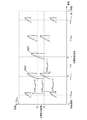
- FIG. 9A, FIG. 9B, FIG. 9C, FIG. 9D, FIG. 9E, and FIG. 9F are explanatory diagrams showing the influence of the Doppler frequency when pulse compression is performed on received signals having different transmission frequencies.
- 10A and 10B are explanatory diagrams showing the influence of the Doppler frequency when band-combining signals after correlation for each transmission frequency.
- FIG. 12A, FIG. 12B, and FIG. 12C are explanatory diagrams showing frequency domain conversion results for the received video signal at the transmission frequency of the transmission radar by CZT. It is explanatory drawing which shows the relationship of the input / output by a frequency domain conversion process.
- 14A and 14B are explanatory diagrams showing the spectrum of a signal based on the received video signal, speed, and distance. It is explanatory drawing which shows the input / output relationship by a correlation process. It is explanatory drawing which shows the spectrum of the signal based on the distance after velocity and the correlation.
- FIG. 18A, FIG. 18B, and FIG. 18C are explanatory views showing the spectrum of a signal based on the speed at the target relative distance of each transmission frequency and the distance after correlation.
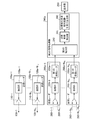
- FIG. 1 is a configuration diagram of a radar apparatus according to the present embodiment.
- the transmission radar 100-n Tx includes an antenna 110-n Tx and a transmission unit 120-n Tx .
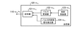
- the transmitter 120-n Tx includes a transmitter 121-n Tx , a pulse modulator 122-n Tx , a local oscillator 123-n Tx , and an intra-pulse modulation signal generator 124-n Tx . .
- the receiving radar 200-1 includes an antenna 210-1, a receiving unit 220-1, and a first signal processor 230-1.
- the receiving unit 220-1 includes a receiver 221-1 and an A / D converter 222-1.
- the first signal processor 230-1 includes a frequency domain conversion unit 231-1, a correlation unit 232-1, and an integration unit 233-1.
- the second signal processor 240 includes a target candidate detection unit 241 and a target relative speed / relative distance / arrival angle calculation unit 242.
- the transmission radar 100-n Tx is a transmission radar that radiates transmission signals of different frequencies, each generated using a pulse signal and an intra-pulse modulation signal that modulates the frequency of the pulse signal.
- the antennas 110-n Tx are antennas that radiate signals transmitted from the transmission units 120-n Tx as transmission RF signals 130-n Tx , respectively.
- Transmitter 121-n Tx in the transmitter unit 120-n Tx is generating a transmission signal based on the pulse in the modulated signal from the pulse signal and the pulse in the modulation signal generator 124-n Tx from the pulse modulator 122-n Tx Is a processing unit.
- the pulse modulator 122-n Tx is a processing unit that generates a pulse signal based on the local oscillation signal from the local oscillator 123-n Tx .
- the local oscillator 123-n Tx is a processing unit that generates a local oscillation signal based on a preset period and pulse width.
- the intra-pulse modulation signal generator 124-n Tx is a processing unit that generates an intra-pulse modulation signal for frequency-modulating the pulse signal.
- the reception radar 200-1 is a processing unit that receives a transmission signal that is radiated from the transmission radar 100-nTx and reflected by the target and returned.
- An antenna 210-1 of the reception radar 200-1 is an antenna for receiving the reception RF signals 260-1-1 to 260-N Tx -1.
- the receiver 221-1 in the receiving unit 220-1 is a processing unit that converts the received signal received by the antenna 210-1 into a received video signal.
- the A / D converter 222-1 is connected to the receiver 221-1. It is a processing unit for A / D converting the output received video signal.
- the frequency domain transforming unit 231-1 in the first signal processor 230-1 converts the received video signal from the receiving unit 220-1 into speed bins having the same target Doppler frequency regardless of the change in the frequency of the transmission signal. It is a processing unit that converts a signal based on speed and distance so as to belong to a number.
- the correlation unit 232-1 performs correlation processing on the output signal of the frequency domain conversion unit 231-1 using a reference signal corresponding to the transmission frequency of the transmission radar 100-n Tx and the speed corresponding to the speed bin number. This is a processing unit for generating a signal based on the speed separated for each transmission frequency of the transmission radar 100-n Tx and the distance after the correlation.
- the integrating unit 233-1 is a processing unit that integrates the output signal of the correlator 232-1 with the target arrival angle candidates and generates a signal based on the band-combined speed and the correlated distance.
- the target candidate detection unit 241 in the second signal processor 240 is a processing unit that detects a target candidate based on the signal strength with respect to the output signal of the integration unit 233-1.
- the target relative speed / relative distance / arrival angle calculation unit 242 is a processing unit that calculates the relative speed, relative distance, and arrival angle of the target candidate.
- the display device 250 is a display device for displaying signal processing results.
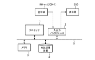
- the radar apparatus includes a processor 1, an input / output interface 2, a memory 3, an external storage device 4, and a signal path 5.
- the processor 1 is a processor for realizing the functions of the transmission radar 100-n Tx , the reception radar 200-1, and the second signal processor 240 in the radar apparatus.
- Output interface 2 is an interface transmitting and receiving the signal from antenna 210-1 of antenna 110-n Tx and receiver radar 200-1 in transmitted radar 100-n Tx, also at the interface of the output signal to the display unit 250 is there.
- the memory 3 includes a program memory that stores various programs for realizing the radar apparatus according to the present embodiment, a work memory that is used when the processor 1 performs data processing, a ROM that is used as a memory that develops signal data, and the like.
- a storage unit such as a RAM.
- the external storage device 4 is used to store various data such as various setting data and signal data of the processor 1.
- a volatile memory such as SDRAM, an HDD, or an SSD can be used.
- a program including an OS (Operating System), various setting data, and various data such as signal data can be stored. Note that data in the memory 3 can be stored in the external storage device 4.
- the signal path 5 is a bus for connecting the processor 1, the input / output interface 2, the memory 3, and the external storage device 4 to each other. Further, there may be a plurality of processors 1 and memories 3, and the plurality of processors 1 and memories 3 may be configured to perform signal processing in cooperation. Furthermore, at least one of the transmission radar 100-n Tx , the reception radar 200-1 and the second signal processor 240 may be configured by dedicated hardware.
- the transmission operation of the transmission radar 100-n Tx will be described with reference to FIG.
- the antennas 110-n Tx are distributed, and the antenna elements may be distributed.
- it may be realized by MIMO (multiple-input and multiple-output) radar and DBF (digital beam forming).
- the local oscillator 123-n Tx generates the local oscillation signal L 0 (t) and outputs it to the pulse modulator 122-n Tx as shown in the equation (1). (Step ST11).
- a L is the amplitude of the local oscillation signal
- ⁇ 0 is the initial phase of the local oscillation signal
- f 0 is the center transmission frequency
- T obs is the observation time.
- the pulse modulator 122-n Tx based on the pulse repetition information indicating the period T pri and the pulse width T 0 set in advance, from equation (2), the local oscillation signal L 0 from the local oscillator 123-n Tx Pulse modulation is performed on (t) to generate a pulse signal L pls (h, t), which is output to the transmitter 121-n Tx (step ST12).
- h is a hit number and H is the number of hits (represented by equation (3), floor (X) is an integer obtained by rounding down the decimal point of variable X).
- the intra-pulse modulation signal generator 124-n Tx uses the frequency modulation amount B nTx and the modulation bandwidth ⁇ B nTx according to the equation (4) to modulate the intra-pulse modulation signal L chp (n Tx , H, t) are generated and output to the transmitter 121-n Tx (step ST13).
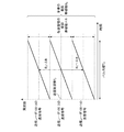
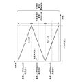
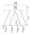
- FIG. 5 shows the relationship between the frequency modulation amount B nTx and the modulation bandwidth ⁇ B nTx of each transmission radar. In the first embodiment, an effect when the modulation bandwidths of the transmission radars are the same will be described. Frequency modulation amount B 2 is zero.
- the transmitter 121-n Tx uses the pulse signal L pls (h, t) and the intra-pulse modulation signal L chp (n Tx , h, t) according to the equation (5) to transmit the RF signal T x (n Tx , h, t) is generated and output to the antenna 110-n Tx (step ST14). Thereafter, the transmission RF signal T x (n Tx , h, t) is radiated into the air from the antenna 110-n Tx (step ST15).
- the transmission RF signal radiated into the air is reflected by the target and enters the antenna 210-1 as a reflected RF signal. Therefore, the antenna 210-1 receives the incident reflected RF signal, and receives the received RF signal Rx (n Rx , h, t) of the receiving radar 200-n Rx expressed by the equation (6) as the receiver 221- 1 (step ST21).
- Rx 0 (n Tx , n Rx , h, t) is a received RF signal received by the receiving radar 200-n Rx from the reflected RF signal of the transmitting radar 100-n Tx expressed by the equation (7),
- a R is the amplitude of the reflected RF signal
- R 0 is the initial target relative distance
- v is the target relative speed
- ⁇ is the target angle
- c is the speed of light
- t ′ is the time within one hit.
- phase difference ⁇ Tx (n Tx ) of the transmission radar 100-n Tx is expressed by equation (8)
- the phase difference ⁇ Rx (n Tx , n Rx ) of the reception radar 200-1 is expressed by equation (9). .
- the receiver 221-1 receives the local oscillation signal L 0 (t) expressed by the equation (1) with respect to the reception RF signal Rx (n Tx , n Rx , h, t) input from the antenna 210-1. Down-converted, and after passing through a band filter (not shown), amplification and phase detection are performed, and the received video signal V ′ (n Rx , h, t) of the receiving radar 200-n Rx expressed by the equation (10) Is output to the A / D converter 222-1 (step ST22).
- V 0 ′ (n Tx , n Rx , h, t) is a reception video signal generated by the reception radar 200-n Rx from the reception video signal of the transmission radar 100-n Tx expressed by the equation (11), AV is the amplitude of the received video signal.
- the A / D converter 222-1 performs A / D conversion on the received video signal V ′ (n Rx , h, t) of the receiving radar 200-n Rx input from the receiver 221-1, A reception video signal V (n Rx , h, m) of the reception radar 200-n Rx represented by Expression (12) is generated and output to the first signal processor 230-1 (step ST23).
- V 0 (n Tx , n Rx , h, m) is a received video obtained by A / D converting the received video signal of the transmission radar 100-n Tx represented by the equation (13) by the receiving radar 200-n Rx.
- Signal, m is a sampling number in PRI, and M in PRI is the number of sampling.
- step ST31 shows the processing of the frequency domain conversion unit 231-1
- step ST32 shows the processing of the correlation unit 232-1
- step ST33 shows the processing of the integration unit 233-1.
- the received video signal V (n Rx , h, m) of the receiving radar 200-n Rx is input from the A / D converter 222-1 to the frequency domain converting unit 231-1.
- the reception video signal V (n Rx , h, m) of the reception radar 200-n Rx is superimposed with a signal modulated by a plurality of transmission radars at different center frequencies as represented by the equation (12).
- the first signal processor 230-1 can improve detection performance by transmitting a plurality of transmission radars, reflecting them at a target, separating the received signals received for each transmission radar, and coherently integrating them. To do.
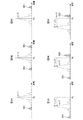
- 9A, 9B, and 9C show signals after correlation for each transmission radar when there is no influence of the Doppler frequency.
- 9A shows a signal after correlation of the transmission radar 100-1
- FIG. 9B shows a transmission radar 100-2
- FIG. 9C shows a signal after correlation of the transmission radar 100-3.
- FIGS. 9A to 9C since the band is different for each transmission radar, the reception signal for each transmission radar can be separated. It can be seen that the target relative distance is integrated.
- cross-correlation occurs due to the influence of adjacent bands, and the side lobe slightly increases (see section 901 in the figure).
- FIG. 9D, FIG. 9E, and FIG. 9F show the signals after correlation for each transmission radar when there is an influence of the Doppler frequency.
- 9D shows the signal after correlation of the transmission radar 100-1
- FIG. 9E shows the transmission radar 100-2
- FIG. 9F shows the correlation signal of the transmission radar 100-3.
- the band is different for each transmission radar, the received signal for each transmission radar can be separated.
- the target relative distance is affected by the influence of the Doppler frequency and is compressed to a distance ⁇ R PC (n Tx ) different from the target relative distance as expressed by the equation (14), there is a problem that the ranging performance deteriorates. is there.
- the side lobe is increased by the cross-correlation, and as shown in the section 902 of FIGS. 9E and 9F, there is an influence of the Doppler frequency, and the side lobe is further increased by the cross-correlation. ing.
- Fig. 10 shows the effect of Doppler frequency when band synthesis is performed.
- FIG. 10A when there is no influence of the Doppler frequency, signals in adjacent bands are coherently combined, power is increased, detection performance is improved, and distance resolution is improved (see section 1001 in the figure).
- FIG. 10B when there is an influence of the Doppler frequency, there is a problem in that the phase of the signal after the correlation between adjacent bands is different and an integration loss occurs (see arrow 1002 in the figure). Further, when there is an influence of the Doppler frequency, there is a problem that the distance to be compressed is different from the target relative distance (see arrow 1003 in the figure).
- a section 1005 indicates a portion where the side lobe is increased due to cross-correlation.
- the Doppler frequency can be obtained by converting the received video signal into the frequency domain in the hit direction.
- FFT fast Fourier transform
- the Doppler frequency is different, and detection and synthesis are difficult. That is, in FFT, the frequency sampling interval is the same regardless of the transmission frequency, and the speed sampling interval is different depending on the transmission frequency.
- the frequency domain transforming unit 231-1 of the first embodiment performs Doppler for each transmission frequency for the purpose of coherently synthesizing the received video signal V (n Rx , h, m) of the receiving radar 200-n Rx.
- Chirp z-transform (CZT: Chirp Z-Transform) is used to convert to the frequency domain while changing the Doppler frequency interval for each different transmission frequency so that the speed bins are the same.
- FIG. 12 shows the frequency domain conversion result for the received video signal of the transmission frequency of the transmission radar 100-n Tx by CZT. However, although the received video signal is sampled by the pulse width per hit, FIG. 12 shows only one sample for the sake of explanation.
- FIG. 12A shows an example of frequency conversion so that the received signal of the transmission radar 100-1 becomes a speed bin indicating the target relative speed v
- FIG. 12B shows the case of the transmission radar 100-2
- FIG. 12C shows the transmission radar 100-3. Shows the case.
- ⁇ v CZT is a velocity sample interval in the frequency domain.
- the frequency domain transform unit 231-1 operates so that the Doppler velocity bins of the signals after the frequency domain transform become the same by changing the CZT transform function based on the transmission frequency.
- the frequency domain transforming unit 231-1 performs CZT represented by Expression (16) on the received video signal V (n Rx , h, m) of the receiving radar 200-n Rx to transform it into the frequency domain, A signal F CZT (n Tx , n Rx , h czt , m) based on speed and distance is generated.
- z nTx -h conversion function CZT corresponding to each transmission frequency (f 0 + B nTx)
- W nTx ⁇ hczt is a CZT conversion range function (equation (18)) corresponding to each transmission frequency (f 0 + B nTx )
- v st is a conversion start speed
- v en is a conversion end speed
- H czt is a sampling after CZT.
- the number, f samp is the sampling frequency (formula (19)).
- the relative speed v CZT (h czt ) of the speed bin number h czt after conversion into the frequency domain is expressed by Expression (20).
- the signal F CZT (n Tx) based on the speed and distance is obtained at any transmission frequency (f 0 + B nTx ) by the processing of the frequency domain transform unit 231-1 according to the equations (16) to (18).
- N Rx , h czt , m) are sampled in the frequency direction from the conversion start speed v st to the conversion end speed v en at the same speed sampling interval ⁇ v czt , and the target is sampled to the same Doppler speed bin.
- the sampling number H czt after CZT can be set arbitrarily, and a desired sampling interval can be obtained.
- the conversion start speed v st and the conversion end speed v en it is possible to arbitrarily set an assumed relative speed.
- the frequency domain transform unit 231-1 converts the CZT represented by the equation (16) into a frequency domain using a fast Fourier transform (FFT) and an inverse fast Fourier transform (IFFT: Inverse FFT) represented by the equation (21).
- FFT fast Fourier transform
- IFFT inverse fast Fourier transform
- DFT Discrete Fourier Transform
- * represents convolution.
- FIG. 13 shows the input / output relationship by the frequency domain conversion processing.
- FIG. 14 shows a spectrum of the received video signal V (n Rx , h, m) and a signal F CZT (n Tx , n Rx , h czt , m) based on speed and distance.
- 14A shows a received video signal
- FIG. 14B shows a signal based on speed and distance.
- the value of the distance indicated by a dotted line is a distance R amb that can be measured without ambiguity.
- FIG. 14 explains that the received video signal having the corresponding transmission frequency appears in the target relative velocity bin.
- the frequency domain transforming unit 231-1 follows the formula (22). Window function processing is performed to generate a received video signal V ′ (n Rx , h, m) after the window function processing.
- the hamming window w ham (m) represented by the equation (23) is used for explanation.
- a window function other than the Hamming window may be used.
- the frequency domain transform unit 231-1 replaces the received video signal V (n, h, m) with the received video signal V ′ (n Rx , h, m) after the window function processing. Is converted into the frequency domain in accordance with Expression (16) or Expression (21), and a signal F CZT (n Tx , n Rx , h czt , m) based on speed and distance is generated.
- the frequency domain transform unit 231-1 outputs a signal F CZT (n Tx , n Rx , h czt , m) based on the speed and distance to the correlation unit 232-1.
- the correlation unit 232-1 correlates the reference signal based on the speed corresponding to each transmission frequency and each speed bin and the signal F CZT (n Tx , n Rx , h czt , m) based on the speed and distance, that is, pulse compression.
- F CZT n Tx , n Rx , h czt , m
- R PC n Tx , n Rx , h czt , l
- a processing block 1501-1 is a pulse compression and processing block 1501- for a signal Fczt (1, n Rx , h czt , m) based on the speed and distance of the transmitting radar 100-1 and the receiving radar 200-n Rx.
- N Tx indicates pulse compression with respect to a signal Fczt (N Tx , n Rx , h czt , m) based on the speed and distance of the transmission radar 100-N Tx and the reception radar 200-n Rx .
- FIG. 16 shows a signal based on the speed and the distance after correlation, and the distance value indicated by a dotted line is a distance R amb that can be measured without ambiguity.
- the correlation is low if the Doppler frequency is not included in the reference signal when performing pulse compression.
- the solid line indicates the transmission signals of the transmission radars 100-1 to 100-3, and the broken line indicates the reception signal that is affected by the Doppler frequency.
- the cross-correlation between adjacent bands becomes high, the unnecessary peak becomes high as shown by a curve 1004 in FIG. 10B, and the distance is shifted as shown by an arrow 1003.
- the correlator 232-1 adds the frequency modulation amount B nTx and the modulation bandwidth ⁇ B nTx of each transmission radar 100-n Tx that is the same as the intra-pulse modulation signal L chp (n Tx , t).
- the reference signal Ex (n Tx , h czt , m) including the Doppler frequency corresponding to the speed of each speed bin is generated according to the equation (24).
- the second term in the equation (24) represents the Doppler frequency corresponding to the speed of each speed bin, and is converted into the frequency domain in the hit direction by the frequency domain converter 231-1 before the pulse compression.
- the signal integrated in the relative velocity bin is not affected by the Doppler frequency and can be pulse-compressed.
- the received video signal from the target for each speed at each transmission frequency is influenced by the Doppler frequency. It is possible to perform pulse compression without any problem.
- the frequency domain is converted into the frequency domain in the hit direction by the frequency domain converter 231-1 before the pulse compression. That is, the signal to be pulse-compressed is not a signal for one hit, but a signal during the observation time, and becomes a signal for H hit.
- the phase based on the target movement distance of the H hit (the third term in the expression (25)) according to the equation (25). ) May also be generated to generate the reference signal Ex (n Tx , h czt , m).
- the correlator 232-1 uses the signal F CZT (n Tx , n Rx , h czt , m) and the reference signal Ex (n Tx , h czt , m) based on the speed and the distance to the expressions (26) and (27). Then, fast Fourier transform (FFT: Fast Fourier Transform) is performed, respectively, and then multiplied (Equation (28)).
- FFT Fast Fourier Transform
- the correlator 232-1 performs fast Fourier inverse transform (IFFT: Inverse Fast Fourier Transform) on the multiplication result F V ⁇ Ex (n Tx , n Rx , h czt , k r ) according to Equation (29).
- IFFT Inverse Fast Fourier Transform
- signals 1801, 1802, and 1803 signals in different bands are compressed, and only the received signal of the transmission radar 100-n Tx is separated and pulse-compressed.
- the correlator 232-1 outputs a signal R PC (n Tx , n Rx , h czt , l) based on the speed separated for each transmission frequency and the distance after correlation to the integrator 233-1.
- the integrating unit 233-1 uses the equation (2) for the signal R PC (n Tx , n Rx , h czt , l) based on the speed separated for each transmission frequency acquired from the correlator 232-1 and the distance after correlation. 30), integration is performed to generate a signal R ⁇ Tx (n ⁇ , n Rx , h czt , l) based on the band synthesized velocity and the correlated distance.
- ⁇ ′ (n ⁇ ) is an arrival angle candidate
- n ⁇ is an arrival angle candidate number
- N ⁇ is the number of arrival angle candidates.
- the signal R PC (n Tx , n Rx , h ctz , l) based on the speed separated for each transmission frequency and the distance after correlation is coherently integrated and band-synthesized.
- a signal R ⁇ Tx (n ⁇ , n Rx , h czt , l) based on the speed and the distance after correlation indicates the maximum value.
- the integrating unit 233-1 outputs a signal R ⁇ Tx (n ⁇ , n Rx , h czt , l) based on the band-combined speed and the correlated distance to the target candidate detecting unit 241 in the second signal processor 240.
- the target candidate detecting unit 241 uses the band intensity obtained from the integrating unit 233-1 and the signal R ⁇ Tx (n ⁇ , n Rx , h czt , l) based on the correlated distance and the signal intensity based on the signal intensity. , Detect target candidates. More specifically, for example, CA-CFAR (Cell Average Constant False Alarm Rate) processing can be considered.
- CA-CFAR Cell Average Constant False Alarm Rate
- the target candidate detection unit 241 includes a signal R ⁇ Tx (n ⁇ , n Rx , h czt , l) based on the band-combined speed and the correlated distance, the arrival angle candidate number n ⁇ ′ of the detected target candidate, the speed The bin number h czt ′ and the sampling number l ′ in the distance direction are output to the target relative speed / relative distance / arrival angle calculator 242.
- Target relative speed and the relative distance and angle of arrival calculator 242 based on the obtained arrival angle candidate number n theta target candidate ', velocity bin number h czt' the distance direction of the sampling number l ', the target according to the formula (31) 'the tgt, target candidate relative distance R according to equation (32)' candidate relative velocity v is calculated tgt.
- ⁇ r IFFT is a sampling interval in the distance direction after correlation.
- the target relative speed / relative distance / arrival angle calculation unit 242 includes a target candidate arrival angle ⁇ ′ ( n ⁇ ′) corresponding to the arrival angle candidate number n ⁇ ′, a target candidate relative speed v ′ tgt , and a target candidate relative distance R ′.
- the tgt is output to the display 250.
- the display unit 250 displays the target candidate arrival angle ⁇ ′ (n ⁇ ′), the target candidate relative speed v ′ tgt and the target candidate relative distance R ′ tgt as target information on the screen as signal processing results.
- a plurality of transmission radars transmit different transmission frequencies, and are received by reflection at a target, the received video signals having different transmission frequencies are not affected by the Doppler frequency.
- the frequency domain transform unit 231-1 transforms the frequency domain by chirp z transformation while changing the Doppler frequency interval for each different transmission frequency so that the Doppler velocity bin is the same for each different transmission frequency. To do.
- the conversion processing to the frequency domain requires a large amount of calculation, but may be a discrete Fourier transform.
- the frequency domain conversion unit 231-1 converts the Doppler speed bin to the same frequency domain for each different transmission frequency, there is no need to detect and calculate the target relative speed, and low SNR (Signal to Noise Ratio: It is possible to obtain a radar apparatus with improved target detection performance (signal-to-noise ratio).
- the correlator 232-1 includes a reference signal Ex (n Tx , h czt , m) based on the speed corresponding to each transmission frequency and each speed bin, and a signal F CZT (n Tx , n Rx , h) based on the speed and distance.
- the signal R PC (n, n, h, m) based on the speed separated for each transmission frequency and the distance after the correlation is generated by performing correlation with czt , m), that is, pulse compression.
- the correlation unit 232-1 performs pulse compression using the reference signal Ex (n Tx , h czt , m) based on the speed corresponding to each transmission frequency and each speed bin, the pulse compression is possible without being affected by the Doppler frequency. Become. As a result, it is possible to obtain a radar apparatus in which distance measurement performance is improved by pulse compression to a target relative distance, and an increase in unnecessary peaks can be suppressed even for a received signal having a Doppler frequency.
- the integrating unit 233-1 performs integration on the signal R PC (n Tx , n Rx , h ctz , l) based on the speed separated for each transmission frequency input from the correlator 232-1 and the distance after the correlation. Then, a signal R ⁇ Tx (n ⁇ , n Rx , h czt , l) is generated based on the band-combined speed and the distance after correlation.
- the received video signals with different transmission frequencies are integrated, but when the transmission frequencies are different, the Doppler frequencies are also different, and as a result, the received video signals with different transmission frequencies have different phases and are not coherent, resulting in an integration loss. There is.
- the correlator 232-1 uses the reference signal Ex (n Tx , h czt , m) based on the speed corresponding to each transmission frequency and each speed bin, so that it becomes coherent and can be integrated without loss. It becomes possible. Therefore, it is possible to obtain a radar apparatus with increased power and improved detection performance after integration.
- a plurality of transmission radars that radiate transmission signals of different frequencies generated by using a pulse signal and an intra-pulse modulation signal that modulates the frequency of the pulse signal
- a reception unit that converts the reception signal of the transmission signal reflected back from the target into a reception video signal, and the reception video signal is set to the same speed bin number regardless of the change in the frequency of the transmission signal.
- a frequency domain conversion unit that converts the signal into a signal based on speed and distance, and a reference signal corresponding to the speed corresponding to the transmission frequency and speed bin number of a plurality of transmission radars with respect to the output signal of the frequency domain conversion unit
- the correlation unit generates a signal based on the speed separated for each transmission frequency of the plurality of transmission radars and the distance after the correlation, and the output signal of the correlation unit
- An integration unit that integrates the target arrival angle candidates and generates a signal based on the band-combined speed and the correlated distance, and a target candidate detection unit that detects a target candidate based on the signal strength with respect to the output signal of the integration unit
- a target relative speed / relative distance / arrival angle calculation unit for calculating the target candidate's relative speed, relative distance, and angle of arrival, so that target detection performance can be improved even when the target Doppler frequency is affected. it can.
- the plurality of transmission radars radiate transmission signals having different frequencies based on the transmission frequencies obtained by frequency-modulating the pulses in ascending or descending order at set frequency intervals. Therefore, signals with different transmission frequencies can be transmitted with a simple configuration.
- the frequency domain conversion unit performs the conversion process by applying the window function process to the received video signal, so that the speed direction of the signal after the frequency domain conversion is changed.
- the side lobes are reduced, and the target can be avoided from being buried in the side lobes.
- the frequency domain transform unit uses the discrete Fourier transform to sample the received video signal after the frequency domain transform at a frequency interval set based on the center transmission frequency. Therefore, a radar apparatus with improved target detection performance can be obtained.
- the frequency domain transform unit uses the chirp z transform to sample the received video signal after the frequency domain transform at an interval set based on the center transmission frequency. Therefore, a radar apparatus with improved target detection performance can be obtained, and processing can be performed with a small amount of calculation.
- the correlation unit uses the reference signal to which the phase based on the target moving distance during the observation time is added, so that the pulse compression can be performed without the influence of the Doppler frequency. it can.
- Embodiment 2 describes a configuration in which N Rx has a plurality of )
- a second signal processor 240a, and a display 250 in which N Rx has a plurality of
- FIG. 20 is a configuration diagram of the transmission unit 120a-n Tx .
- the transmitters 120a-n Tx include a transmitter 121-n Tx , a pulse modulator 122-n Tx , a local oscillator 123-n Tx, and an intra-pulse modulation signal generator 124a-n Tx . And except for the intra-pulse modulation signal generators 124a-n Tx .
- FIG. 21 is a configuration diagram of the first signal processor 230a-n Rx .
- the first signal processor 230a-n Rx includes a frequency domain transform unit 231-n Rx , a correlation unit 232a-n Rx, and an integration unit 233-n Rx , and a correlation unit 232a-n.
- the second embodiment is the same as the first embodiment.
- the second signal processor 240a is different from the first embodiment in that a second integration unit 243 is provided.
- the intra-pulse modulation signal generators 124a-n Tx of the transmitters 120a-n Tx use the frequency modulation amount Bn Tx and the modulation bandwidth ⁇ Bn Tx according to the equation (33), and the frequency modulation of adjacent frequency bands is complex.
- An intra-pulse modulation signal L chp (n Tx , t) for frequency-modulating the pulse signal is generated so as to be conjugate and output to the transmitter 121-n Tx .
- ⁇ uses a minus sign (that is, down-chirp frequency modulation) when n Tx is an odd number, and a plus sign (that is, up-chirp frequency modulation) when n Tx is an odd number.
- FIG. 22 shows the relationship between the frequency modulation amount Bn Tx and the modulation bandwidth ⁇ Bn Tx of each transmission radar and the frequency modulation. Frequency modulation amount B 2 is zero.
- Correlator 232a-n Rx a pulse in the modulated signal L chp (n Tx, t) and the frequency modulation amount B nTx the same each transmitted radar 100a-n Tx addition to the modulation bandwidth DerutaBn Tx, the speed of each speed bin A reference signal Ex (n Tx , h czt , m) including the corresponding Doppler frequency is generated according to the equation (34).
- the phase based on the target moving distance of the H hit (the first in the formula (35)
- the reference signal Ex (n Tx , h czt , m) may also be generated with the addition of item 3).
- ⁇ is a sign of ⁇ (that is, down-chirp frequency modulation) when n Tx is odd, and a sign of + (that is, frequency modulation of up-chirp) when n Tx is an odd number. Is used). Since the subsequent pulse compression processing is the same as that of the correlation unit 232-1 of the first embodiment, the description thereof is omitted here.
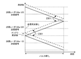
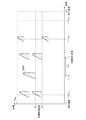
- FIG. 23 shows a received signal when there is a Doppler frequency.
- the transmission signal of the transmission radar 100a-n Tx is indicated by a solid line
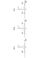
- the reception signal affected by the Doppler frequency is indicated by a broken line. Since the transmission signals of the transmission radars 100a-n Tx are made complex conjugate in the frequency modulation of adjacent bands, the cross-correlation cancels out during pulse compression (see arrow 2301), and as shown in FIG.
- 24A shows the signal after correlation of the transmission radar 100a-1
- FIG. 24B shows the signal after correlation of the transmission radar 100a-2
- FIG. 24C shows the signal after correlation of the transmission radar 100a-3.
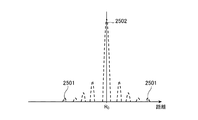
- band integration is performed by the integrating unit 233-n Rx , there is no influence of cross-correlation, side lobes do not increase, and low side lobe integration results can be obtained (see section 2501).
- the bands are combined, the power is increased and the distance resolution is improved (see section 2502). That is, it is possible to obtain a radar apparatus with improved detection performance. Also, as shown in FIG.
- the frequency modulation of the target frequency band may be complex conjugate.
- the transmission signal of the transmission radar 100a-1 and the transmission signal of the transmission radar 100a-4, and the transmission signal of the transmission radar 100a-2 and the transmission signal of the transmission radar 100a-3 are complex conjugates. Even with such a configuration, an effect similar to that in the case of transmitting a transmission signal in which the frequency modulation of adjacent bands is complex conjugate can be obtained.
- Second integrator section 243 the signal based on the distance after correlation with band synthesis velocity from the first signal processor 230-1 ⁇ N Rx R ⁇ Tx (n ⁇ , n Rx, h czt, l) is input Is done.
- the second integration unit 243 applies the equation (36) to the signal R ⁇ Tx (n ⁇ , n Rx , h czt , l) based on the band-combined speed for each reception radar 200a-n Rx and the correlated distance.
- the signal R ⁇ Tx (n ⁇ , n Rx , h ctz , l) based on the band-combined speed for each of the receiving radars 200a-n Rx and the correlated distance is integrated coherently. Then, the signal R ⁇ Tx (n ⁇ , n Rx , h czt , l) based on the integrated speed and the distance after the correlation shows the maximum value.
- the second integration unit 243 outputs signals R ⁇ Tx, Rx (n ⁇ , h ctz , l) based on the integrated speed and the correlated distance to the target candidate detection unit 241.
- the operations after the target candidate detection unit 241 are the same as those in the first embodiment.
- the frequency modulation of the adjacent bands of the transmission signals from the transmission radars 100a-n Tx is complex conjugate, the cross-correlation cancels out during the pulse compression, Unnecessary peaks do not occur, and side lobes are not increased. Further, even when band synthesis is performed by the integrating unit 233-1n Rx , there is no influence of cross-correlation, the side lobe does not increase, and an integration result of a low side lobe can be obtained. That is, it is possible to obtain a radar apparatus with improved detection performance.
- the second integration unit 243 integrates the signals for each of the reception radars 200a-n Rx, it is possible to obtain a radar apparatus with increased power and improved detection performance. Further, by integrating the signals for each of the receiving radars 200a-n Rx , the antenna aperture length is virtually increased, so that the angular resolution is improved.
- the signal based on the band-combined speed and the correlated distance is integrated with the target arrival angle candidate, and the signal based on the integrated speed and the correlated distance is obtained.
- the target candidate detection unit detects the target candidate for the output signal of the second integration unit instead of the integration unit, so that the power is increased and the detection performance is increased. And the angular resolution can be improved.
- a plurality of transmission radars have different frequencies based on transmission frequencies that are frequency-modulated in ascending order and descending order in the pulse so that the frequency modulation of adjacent frequency bands becomes complex conjugate. Since the transmission signal is radiated at a set frequency interval, the cross-correlation cancels during pulse compression, no unnecessary peak occurs, and the side lobe does not increase. As a result, a radar device with improved detection performance can be obtained.
- the plurality of transmission radars are different based on the transmission frequency obtained by frequency modulation in the ascending order and descending order in the pulse so that the frequency modulation of the target frequency band becomes a complex conjugate. Since the transmission signal of the frequency is radiated at the set frequency interval, the cross-correlation cancels out at the time of pulse compression, an unnecessary peak does not occur, and the side lobe does not increase. As a result, a radar device with improved detection performance can be obtained.
- Embodiment 3 In the radar apparatus according to the third embodiment, the second signal processor 240a in the radar apparatus according to the second embodiment is replaced with a second signal processor 240b.
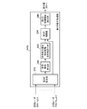
- the configuration of the second signal processor 240b is illustrated in FIG. 27. Note that the configurations of the transmission radars 100a-n Tx and the reception radars 200a-n Rx in the radar apparatus of the third embodiment are the same as those of the second embodiment shown in FIG. This is explained with the aid of.
- the second signal processor 240b of Embodiment 3 includes a second integration unit 243, a target candidate detection unit 241, a target relative speed / relative distance / arrival angle calculation unit 242, a second A correlation unit 244 and a second target candidate detection unit 245 are provided.
- the configurations and operations of the second integration unit 243, the target candidate detection unit 241, and the target relative speed / relative distance / arrival angle calculation unit 242 are the same as those in the second embodiment.
- the second correlator 244 receives signals R ⁇ Tx, Rx (n ⁇ , h czt , l) based on the integrated speed and the distance after correlation, and the relative speed, relative distance, and angle of arrival of the target candidate. .
- the second correlator 244 generates a signal based on the integrated speed and the distance after the correlation based on the relative speed, the relative distance, and the arrival angle of the target candidate, and sets it as the two-dimensional reference signal Ex (n t ).
- the two-dimensional reference signal Ex (n t ) is set to the target relative speed v, the relative distance R 0 , and the arrival angle of the first target candidate 2801 as shown in FIG. Can be generated.
- the two-dimensional reference signal Ex ( nt ) of the second target candidate 2802 is generated based on the target relative speed v ⁇ v amb , the relative distance R 2 , and the arrival angle of the second target candidate 2802 as shown in FIG. can do.
- n t is a target candidate number.
- the second correlator 244 generates signals R ⁇ Tx, Rx (n ⁇ , h czt , l) and a two-dimensional reference signal Ex (n t ) based on the speed integrated according to equation (39) and the distance after correlation. 2 correlation processing is performed to generate a second correlated signal R 2 (n t ) with the target candidate.
- fft2 (X) represents the signal after the two-dimensional FFT of the signal X
- ift2 (X) represents the signal after the two-dimensional IFFT of the signal X
- the complex conjugate of the signal Y of Y * The second correlator 244 outputs the second correlated signal R 2 (n t ) with the target candidate to the second target candidate detector 245.
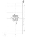
- the second target candidate detection unit 245 detects a target candidate based on the signal strength for the second correlated signal R 2 (n t ) acquired from the second correlation unit 244. However, the second target candidate detection unit 245 distinguishes whether the target is a true target or a virtual image from among the target candidates, and the speed difference is ⁇ v w / 2 and the distance difference is ⁇ as shown in FIG. Target candidates for R w / 2 are detected based on the signal intensity (see detection range 3001). That is, in the case of a true target, the speed difference is 0 and the distance difference is 0, so the vicinity of the speed difference 0 and the distance difference 0 is set as a detection target.
- the speed difference range v w and the distance difference range R w based on the velocity v amb that can be measured without ambiguity are calculated according to the equation (40).
- the speed difference and the distance are small.
- the speed difference and the distance difference are large. Therefore, by providing a detection range from the signal after the second correlation, the target and the virtual image can be distinguished. Thus, false alarms are reduced and detection performance is improved. Therefore, in the case of the signal state shown in FIG.
- the second target candidate detection unit 245 outputs the target candidate arrival angle, target candidate relative speed, and target candidate relative distance of the detected target candidate to the display 250.
- the signal R ⁇ Tx, Rx (n ⁇ , h czt , l) and the two-dimensional reference signal based on the speed integrated by the second correlator 244 and the distance after the correlation.
- Ex (n t ) second correlation processing is performed to generate a second correlated signal R 2 (n t ) with the target candidate, and the second target candidate detecting unit 245 performs the second correlated processing. Since the target candidate is detected for the signal R 2 (n t ) based on the signal strength, the target and the virtual image can be distinguished from the target candidates, the false alarm is reduced, and the detection performance is improved. An improved radar apparatus can be obtained.
- the two-dimensional reference based on the relative speed, the relative distance, and the arrival angle of the target candidate with respect to the signal based on the band synthesized speed and the correlated distance.
- a second correlation unit that performs correlation processing using the signal and generates a signal after the second correlation processing; and a second candidate that detects a target candidate based on the signal strength for the output signal of the second correlation unit Therefore, it is possible to distinguish between a target and a virtual image from among the target candidates, and it is possible to obtain a radar apparatus with reduced false alarms and improved detection performance.
- the radar apparatus relates to a configuration capable of improving the target detection performance even when there is an influence of the target Doppler frequency, and is suitable for use in a MIMO radar or the like.
- 100-n Tx transmitter radar 110-n Tx antenna, 120-n Tx , 120a-n Tx transmitter, 121-n Tx transmitter, 122-n Tx pulse modulator, 123-n Tx local oscillator, 124-n Tx , 124a-n Tx intra-pulse modulation signal generator, 200-n Rx , 200a-n Rx reception radar, 210-n Rx antenna, 220-n Rx receiver, 221-n Rx receiver, 222-n Rx A / D converter, 230-n Rx , 230a-n Rx first signal processor, 231-n Rx frequency domain transformer, 232-n Rx , 232a-n Rx correlator, 233-n Rx integrator, 240 , 240a, 240b second signal processor, 241 target candidate detection unit, 242 target relative speed / relative distance / arrival angle calculation unit, 243 second integration unit, 244 second Seki unit, 245 second target candidate detection unit, 250 display.
Landscapes
- Engineering & Computer Science (AREA)
- Radar, Positioning & Navigation (AREA)
- Remote Sensing (AREA)
- Computer Networks & Wireless Communication (AREA)
- Physics & Mathematics (AREA)
- General Physics & Mathematics (AREA)
- Radar Systems Or Details Thereof (AREA)
Priority Applications (5)
| Application Number | Priority Date | Filing Date | Title |
|---|---|---|---|
| EP16892441.3A EP3407085B1 (de) | 2016-02-29 | 2016-02-29 | Radarvorrichtung |
| JP2017559724A JP6279187B2 (ja) | 2016-02-29 | 2016-02-29 | レーダ装置 |
| US16/074,362 US10746865B2 (en) | 2016-02-29 | 2016-02-29 | Radar system |
| CN201680082136.9A CN108713154B (zh) | 2016-02-29 | 2016-02-29 | 雷达装置 |
| PCT/JP2016/056045 WO2017149596A1 (ja) | 2016-02-29 | 2016-02-29 | レーダ装置 |
Applications Claiming Priority (1)
| Application Number | Priority Date | Filing Date | Title |
|---|---|---|---|
| PCT/JP2016/056045 WO2017149596A1 (ja) | 2016-02-29 | 2016-02-29 | レーダ装置 |
Publications (1)
| Publication Number | Publication Date |
|---|---|
| WO2017149596A1 true WO2017149596A1 (ja) | 2017-09-08 |
Family
ID=59743541
Family Applications (1)
| Application Number | Title | Priority Date | Filing Date |
|---|---|---|---|
| PCT/JP2016/056045 Ceased WO2017149596A1 (ja) | 2016-02-29 | 2016-02-29 | レーダ装置 |
Country Status (5)
| Country | Link |
|---|---|
| US (1) | US10746865B2 (de) |
| EP (1) | EP3407085B1 (de) |
| JP (1) | JP6279187B2 (de) |
| CN (1) | CN108713154B (de) |
| WO (1) | WO2017149596A1 (de) |
Cited By (11)
| Publication number | Priority date | Publication date | Assignee | Title |
|---|---|---|---|---|
| JP6425863B1 (ja) * | 2018-02-13 | 2018-11-21 | 三菱電機株式会社 | レーダ装置 |
| WO2019043749A1 (ja) * | 2017-08-28 | 2019-03-07 | 三菱電機株式会社 | レーダ装置 |
| WO2019082269A1 (ja) * | 2017-10-24 | 2019-05-02 | 三菱電機株式会社 | レーダ装置 |
| EP3511734A1 (de) * | 2018-01-11 | 2019-07-17 | Infineon Technologies AG | System und verfahren zur verbesserung der reichweitengenauigkeit im fmcw-radar unter verwendung von fsk-moduliertem chirp |
| JP2020016474A (ja) * | 2018-07-23 | 2020-01-30 | 株式会社東芝 | レーダシステム及び信号処理方法 |
| JP6664554B1 (ja) * | 2018-11-16 | 2020-03-13 | 三菱電機株式会社 | レーダ装置及び信号処理方法 |
| JP2020051802A (ja) * | 2018-09-25 | 2020-04-02 | パナソニックIpマネジメント株式会社 | レーダ装置及び物標判定方法 |
| CN111157981A (zh) * | 2018-11-08 | 2020-05-15 | 英飞凌科技股份有限公司 | 多入多出调频连续波雷达系统 |
| EP3746806A1 (de) * | 2018-01-29 | 2020-12-09 | Robert Bosch GmbH | Verfahren und vorrichtung zum betreiben von mehreren sensoren eines fahrzeugs |
| JPWO2021240810A1 (de) * | 2020-05-29 | 2021-12-02 | ||
| JP7090826B1 (ja) * | 2021-10-25 | 2022-06-24 | 三菱電機株式会社 | レーダ装置 |
Families Citing this family (16)
| Publication number | Priority date | Publication date | Assignee | Title |
|---|---|---|---|---|
| US10613212B2 (en) * | 2017-08-14 | 2020-04-07 | Oculii Corp. | Systems and methods for doppler-enhanced radar tracking |
| DE102017119624A1 (de) * | 2017-08-28 | 2019-04-18 | HELLA GmbH & Co. KGaA | Verfahren zum Betrieb eines Radarsystems eines Fahrzeuges |
| US10564277B2 (en) | 2018-01-30 | 2020-02-18 | Oculii Corp. | Systems and methods for interpolated virtual aperature radar tracking |
| CN113330324B (zh) * | 2019-01-31 | 2023-06-06 | 三菱电机株式会社 | 雷达装置和信号处理方法 |
| US11313948B2 (en) * | 2019-07-08 | 2022-04-26 | GM Global Technology Operations LLC | Radar system and method for identifying multiple targets in a beam response spectrum |
| CN112433214B (zh) * | 2019-08-08 | 2024-09-24 | 华为技术有限公司 | 一种雷达信号发送方法及装置 |
| CN110672875B (zh) * | 2019-10-21 | 2021-02-23 | 中国科学院电子学研究所 | 基于Chirp-Z变换的表面水流速度检测方法 |
| US11994578B2 (en) | 2019-12-13 | 2024-05-28 | Oculli Corp. | Systems and methods for virtual doppler and/or aperture enhancement |
| US11047974B1 (en) | 2019-12-13 | 2021-06-29 | Oculii Corp. | Systems and methods for virtual doppler and/or aperture enhancement |
| US11041940B1 (en) | 2019-12-20 | 2021-06-22 | Oculii Corp. | Systems and methods for phase-modulated radar detection |
| WO2022026033A1 (en) | 2020-06-16 | 2022-02-03 | Oculii Corp. | System and method for radar interference mitigation |
| KR102342749B1 (ko) * | 2020-07-30 | 2021-12-23 | 국방과학연구소 | 재밍신호 생성장치 및 그 방법 |
| WO2022104259A1 (en) * | 2020-11-16 | 2022-05-19 | Oculii Corp. | System and method for radar-based localization and/or mapping |
| CN112558059A (zh) * | 2020-11-27 | 2021-03-26 | 森思泰克河北科技有限公司 | 雷达测角方法及雷达 |
| US11846701B1 (en) * | 2021-03-08 | 2023-12-19 | GM Global Technology Operations LLC | Long signal integration of multiple velocity hypotheses |
| US11561299B1 (en) | 2022-06-03 | 2023-01-24 | Oculii Corp. | System and method for multi-waveform radar tracking |
Citations (3)
| Publication number | Priority date | Publication date | Assignee | Title |
|---|---|---|---|---|
| JP2007033129A (ja) * | 2005-07-25 | 2007-02-08 | Mitsubishi Electric Corp | 分散ネットワーク・レーダ装置 |
| JP2007508545A (ja) * | 2003-10-10 | 2007-04-05 | レイセオン・カンパニー | レンジ、レーダ感度、及び角度精度の強化のための複数レーダ結合 |
| JP2014222168A (ja) * | 2013-05-13 | 2014-11-27 | 三菱電機株式会社 | レーダ装置 |
Family Cites Families (26)
| Publication number | Priority date | Publication date | Assignee | Title |
|---|---|---|---|---|
| US5374931A (en) * | 1989-12-27 | 1994-12-20 | Raytheon Company | Radar target velocity estimator |
| US7038612B2 (en) * | 2003-08-05 | 2006-05-02 | Raytheon Company | Method for SAR processing without INS data |
| EP1718179A2 (de) * | 2004-01-16 | 2006-11-08 | GHZ TR Corporation | Verfahren und vorrichtung für kraftfahrzeugradarsensoren |
| GB0523676D0 (en) * | 2005-11-21 | 2005-12-28 | Plextek Ltd | Radar system |
| US7450057B2 (en) * | 2006-10-20 | 2008-11-11 | Northrop Grumman Space & Missions Systems Corp. | Signal processing for accelerating moving targets |
| US7439906B1 (en) * | 2007-01-25 | 2008-10-21 | The United States Of America As Represented By The Secretary Of The Navy | Doppler-compensated radar pulse compression processing system and method |
| CN101452073B (zh) * | 2007-11-30 | 2011-12-28 | 清华大学 | 基于多发多收频分雷达的宽带信号合成方法 |
| US7791528B2 (en) * | 2008-11-24 | 2010-09-07 | Autoliv Asp, Inc. | Method and apparatus for radar signal processing |
| JP5595238B2 (ja) * | 2010-11-16 | 2014-09-24 | 三菱電機株式会社 | レーダ装置 |
| FR2972808B1 (fr) * | 2011-03-17 | 2013-04-12 | Thales Sa | Procede de surveillance radar et d'acquisition de signaux radar |
| JP5871559B2 (ja) * | 2011-10-20 | 2016-03-01 | 三菱電機株式会社 | レーダ装置 |
| US9529081B2 (en) * | 2013-04-03 | 2016-12-27 | The Boeing Company | Using frequency diversity to detect objects |
| JP6331195B2 (ja) * | 2014-09-29 | 2018-05-30 | パナソニックIpマネジメント株式会社 | レーダ装置 |
| JP6396244B2 (ja) * | 2015-03-25 | 2018-09-26 | パナソニック株式会社 | レーダ装置 |
| US20160363648A1 (en) * | 2015-06-15 | 2016-12-15 | Humatics Corporation | High precision motion tracking with time of flight measurement systems |
| WO2016205219A1 (en) * | 2015-06-15 | 2016-12-22 | Humatics Corporation | High precision time of flight measurement system for industrial automation |
| JP6818541B2 (ja) * | 2016-03-14 | 2021-01-20 | パナソニック株式会社 | レーダ装置および測位方法 |
| JP2017173227A (ja) * | 2016-03-25 | 2017-09-28 | パナソニック株式会社 | レーダ装置及びレーダ方法 |
| US9791551B1 (en) * | 2016-04-25 | 2017-10-17 | Uhnder, Inc. | Vehicular radar system with self-interference cancellation |
| JP6853642B2 (ja) * | 2016-09-26 | 2021-03-31 | パナソニック株式会社 | レーダ装置 |
| EP3301470A3 (de) * | 2016-09-29 | 2018-06-20 | Panasonic Corporation | Multiradarsystem |
| US10746862B2 (en) * | 2017-02-07 | 2020-08-18 | Saab Ab | Short range radar cohabitation |
| WO2018158353A1 (en) * | 2017-03-03 | 2018-09-07 | Iee International Electronics & Engineering S.A. | Method and system for obtaining an adaptive angle-doppler ambiguity function in mimo radars |
| US10690743B2 (en) * | 2017-08-17 | 2020-06-23 | GM Global Technology Operations LLC | Doppler measurements to resolve angle of arrival ambiguity of wide aperture radar |
| US10901065B2 (en) * | 2017-10-11 | 2021-01-26 | The Boeing Company | Location determination of an emitter using frequency-of-arrival (FOA) measured from a single moving platform |
| US10754008B2 (en) * | 2018-02-15 | 2020-08-25 | GM Global Technology Operations LLC | Vehicle radar system that addresses doppler frequency shift and method of using the same |
-
2016
- 2016-02-29 CN CN201680082136.9A patent/CN108713154B/zh active Active
- 2016-02-29 JP JP2017559724A patent/JP6279187B2/ja active Active
- 2016-02-29 EP EP16892441.3A patent/EP3407085B1/de active Active
- 2016-02-29 US US16/074,362 patent/US10746865B2/en active Active
- 2016-02-29 WO PCT/JP2016/056045 patent/WO2017149596A1/ja not_active Ceased
Patent Citations (3)
| Publication number | Priority date | Publication date | Assignee | Title |
|---|---|---|---|---|
| JP2007508545A (ja) * | 2003-10-10 | 2007-04-05 | レイセオン・カンパニー | レンジ、レーダ感度、及び角度精度の強化のための複数レーダ結合 |
| JP2007033129A (ja) * | 2005-07-25 | 2007-02-08 | Mitsubishi Electric Corp | 分散ネットワーク・レーダ装置 |
| JP2014222168A (ja) * | 2013-05-13 | 2014-11-27 | 三菱電機株式会社 | レーダ装置 |
Cited By (23)
| Publication number | Priority date | Publication date | Assignee | Title |
|---|---|---|---|---|
| JPWO2019043749A1 (ja) * | 2017-08-28 | 2019-11-07 | 三菱電機株式会社 | レーダ装置 |
| WO2019043749A1 (ja) * | 2017-08-28 | 2019-03-07 | 三菱電機株式会社 | レーダ装置 |
| WO2019082269A1 (ja) * | 2017-10-24 | 2019-05-02 | 三菱電機株式会社 | レーダ装置 |
| EP3511734A1 (de) * | 2018-01-11 | 2019-07-17 | Infineon Technologies AG | System und verfahren zur verbesserung der reichweitengenauigkeit im fmcw-radar unter verwendung von fsk-moduliertem chirp |
| CN110031806A (zh) * | 2018-01-11 | 2019-07-19 | 英飞凌科技股份有限公司 | 利用fsk调制的啁啾提高fmcw雷达中的范围精度的系统和方法 |
| CN110031806B (zh) * | 2018-01-11 | 2024-06-18 | 英飞凌科技股份有限公司 | 利用fsk调制的啁啾提高fmcw雷达中的范围精度的系统和方法 |
| US10718860B2 (en) | 2018-01-11 | 2020-07-21 | Infineon Technologies Ag | System and method to improve range accuracy in FMCW radar using FSK modulated chirps |
| EP3746806A1 (de) * | 2018-01-29 | 2020-12-09 | Robert Bosch GmbH | Verfahren und vorrichtung zum betreiben von mehreren sensoren eines fahrzeugs |
| WO2019159231A1 (ja) * | 2018-02-13 | 2019-08-22 | 三菱電機株式会社 | レーダ装置 |
| JP6425863B1 (ja) * | 2018-02-13 | 2018-11-21 | 三菱電機株式会社 | レーダ装置 |
| US11960023B2 (en) | 2018-02-13 | 2024-04-16 | Mitsubishi Electric Corporation | Radar device |
| JP2020016474A (ja) * | 2018-07-23 | 2020-01-30 | 株式会社東芝 | レーダシステム及び信号処理方法 |
| JP7182929B2 (ja) | 2018-07-23 | 2022-12-05 | 株式会社東芝 | レーダシステム及び信号処理方法 |
| JP7108929B2 (ja) | 2018-09-25 | 2022-07-29 | パナソニックIpマネジメント株式会社 | レーダ装置及び物標判定方法 |
| JP2020051802A (ja) * | 2018-09-25 | 2020-04-02 | パナソニックIpマネジメント株式会社 | レーダ装置及び物標判定方法 |
| CN111157981A (zh) * | 2018-11-08 | 2020-05-15 | 英飞凌科技股份有限公司 | 多入多出调频连续波雷达系统 |
| CN111157981B (zh) * | 2018-11-08 | 2024-05-24 | 英飞凌科技股份有限公司 | 多入多出调频连续波雷达系统 |
| JP6664554B1 (ja) * | 2018-11-16 | 2020-03-13 | 三菱電機株式会社 | レーダ装置及び信号処理方法 |
| JP7109710B2 (ja) | 2020-05-29 | 2022-07-29 | 三菱電機株式会社 | レーダ装置及びレーダ信号処理方法 |
| WO2021240810A1 (ja) * | 2020-05-29 | 2021-12-02 | 三菱電機株式会社 | レーダ装置及びレーダ信号処理方法 |
| JPWO2021240810A1 (de) * | 2020-05-29 | 2021-12-02 | ||
| JP7090826B1 (ja) * | 2021-10-25 | 2022-06-24 | 三菱電機株式会社 | レーダ装置 |
| WO2023073763A1 (ja) * | 2021-10-25 | 2023-05-04 | 三菱電機株式会社 | レーダ装置 |
Also Published As
| Publication number | Publication date |
|---|---|
| JP6279187B2 (ja) | 2018-02-14 |
| EP3407085A4 (de) | 2019-02-06 |
| EP3407085B1 (de) | 2020-04-08 |
| JPWO2017149596A1 (ja) | 2018-03-15 |
| CN108713154A (zh) | 2018-10-26 |
| CN108713154B (zh) | 2022-04-15 |
| EP3407085A1 (de) | 2018-11-28 |
| US10746865B2 (en) | 2020-08-18 |
| US20190339374A1 (en) | 2019-11-07 |
Similar Documents
| Publication | Publication Date | Title |
|---|---|---|
| JP6279187B2 (ja) | レーダ装置 | |
| JP6644193B2 (ja) | レーダ装置 | |
| CN104937436B (zh) | 雷达装置 | |
| JP6576595B2 (ja) | レーダ装置 | |
| US7511659B2 (en) | Radar device | |
| JP3821688B2 (ja) | レーダ装置 | |
| JP5871559B2 (ja) | レーダ装置 | |
| EP2363727B1 (de) | Radarvorrichtung und Zielerkennungsverfahren | |
| CN108885254A (zh) | 物体检测装置 | |
| JP6164918B2 (ja) | レーダ装置 | |
| JP2010169671A (ja) | レーダ装置 | |
| KR20190135267A (ko) | Cw 레이더 및 cw 레이더를 이용한 거리 측정 방법 | |
| JP6573748B2 (ja) | レーダ装置 | |
| JP6567226B2 (ja) | レーダ装置 | |
| JP3865761B2 (ja) | レーダ装置 | |
| US11960023B2 (en) | Radar device |
Legal Events
| Date | Code | Title | Description |
|---|---|---|---|
| ENP | Entry into the national phase |
Ref document number: 2017559724 Country of ref document: JP Kind code of ref document: A |
|
| WWE | Wipo information: entry into national phase |
Ref document number: 2016892441 Country of ref document: EP |
|
| NENP | Non-entry into the national phase |
Ref country code: DE |
|
| ENP | Entry into the national phase |
Ref document number: 2016892441 Country of ref document: EP Effective date: 20180822 |
|
| 121 | Ep: the epo has been informed by wipo that ep was designated in this application |
Ref document number: 16892441 Country of ref document: EP Kind code of ref document: A1 |