WO2017149618A1 - Dispositif de commande, dispositif de commande de production d'énergie, procédé de commande, système et programme - Google Patents
Dispositif de commande, dispositif de commande de production d'énergie, procédé de commande, système et programme Download PDFInfo
- Publication number
- WO2017149618A1 WO2017149618A1 PCT/JP2016/056115 JP2016056115W WO2017149618A1 WO 2017149618 A1 WO2017149618 A1 WO 2017149618A1 JP 2016056115 W JP2016056115 W JP 2016056115W WO 2017149618 A1 WO2017149618 A1 WO 2017149618A1
- Authority
- WO
- WIPO (PCT)
- Prior art keywords
- power generation
- output
- surplus
- power
- control device
- Prior art date
- Legal status (The legal status is an assumption and is not a legal conclusion. Google has not performed a legal analysis and makes no representation as to the accuracy of the status listed.)
- Ceased
Links
Images









Classifications
-
- H—ELECTRICITY
- H02—GENERATION; CONVERSION OR DISTRIBUTION OF ELECTRIC POWER
- H02J—ELECTRIC POWER NETWORKS; CIRCUIT ARRANGEMENTS OR SYSTEMS FOR SUPPLYING OR DISTRIBUTING ELECTRIC POWER; SYSTEMS FOR STORING ELECTRIC ENERGY
- H02J3/00—Circuit arrangements for AC mains or AC distribution networks
- H02J3/28—Arrangements for balancing of the load in networks by storage of energy
-
- G—PHYSICS
- G05—CONTROLLING; REGULATING
- G05B—CONTROL OR REGULATING SYSTEMS IN GENERAL; FUNCTIONAL ELEMENTS OF SUCH SYSTEMS; MONITORING OR TESTING ARRANGEMENTS FOR SUCH SYSTEMS OR ELEMENTS
- G05B15/00—Systems controlled by a computer
- G05B15/02—Systems controlled by a computer electric
-
- H—ELECTRICITY
- H02—GENERATION; CONVERSION OR DISTRIBUTION OF ELECTRIC POWER
- H02J—ELECTRIC POWER NETWORKS; CIRCUIT ARRANGEMENTS OR SYSTEMS FOR SUPPLYING OR DISTRIBUTING ELECTRIC POWER; SYSTEMS FOR STORING ELECTRIC ENERGY
- H02J3/00—Circuit arrangements for AC mains or AC distribution networks
- H02J3/003—Load forecast, e.g. methods or systems for forecasting future load demand
-
- H—ELECTRICITY
- H02—GENERATION; CONVERSION OR DISTRIBUTION OF ELECTRIC POWER
- H02J—ELECTRIC POWER NETWORKS; CIRCUIT ARRANGEMENTS OR SYSTEMS FOR SUPPLYING OR DISTRIBUTING ELECTRIC POWER; SYSTEMS FOR STORING ELECTRIC ENERGY
- H02J3/00—Circuit arrangements for AC mains or AC distribution networks
- H02J3/38—Arrangements for feeding a single network from two or more generators or sources in parallel; Arrangements for feeding already energised networks from additional generators or sources in parallel
-
- H—ELECTRICITY
- H02—GENERATION; CONVERSION OR DISTRIBUTION OF ELECTRIC POWER
- H02J—ELECTRIC POWER NETWORKS; CIRCUIT ARRANGEMENTS OR SYSTEMS FOR SUPPLYING OR DISTRIBUTING ELECTRIC POWER; SYSTEMS FOR STORING ELECTRIC ENERGY
- H02J3/00—Circuit arrangements for AC mains or AC distribution networks
- H02J3/38—Arrangements for feeding a single network from two or more generators or sources in parallel; Arrangements for feeding already energised networks from additional generators or sources in parallel
- H02J3/381—Dispersed generators
-
- H—ELECTRICITY
- H02—GENERATION; CONVERSION OR DISTRIBUTION OF ELECTRIC POWER
- H02J—ELECTRIC POWER NETWORKS; CIRCUIT ARRANGEMENTS OR SYSTEMS FOR SUPPLYING OR DISTRIBUTING ELECTRIC POWER; SYSTEMS FOR STORING ELECTRIC ENERGY
- H02J3/00—Circuit arrangements for AC mains or AC distribution networks
- H02J3/38—Arrangements for feeding a single network from two or more generators or sources in parallel; Arrangements for feeding already energised networks from additional generators or sources in parallel
- H02J3/46—Controlling the sharing of generated power between the generators, sources or networks
-
- H—ELECTRICITY
- H02—GENERATION; CONVERSION OR DISTRIBUTION OF ELECTRIC POWER
- H02J—ELECTRIC POWER NETWORKS; CIRCUIT ARRANGEMENTS OR SYSTEMS FOR SUPPLYING OR DISTRIBUTING ELECTRIC POWER; SYSTEMS FOR STORING ELECTRIC ENERGY
- H02J7/00—Circuit arrangements for charging or discharging batteries or for supplying loads from batteries
- H02J7/50—Circuit arrangements for charging or discharging batteries or for supplying loads from batteries acting upon multiple batteries simultaneously or sequentially
-
- H—ELECTRICITY
- H02—GENERATION; CONVERSION OR DISTRIBUTION OF ELECTRIC POWER
- H02J—ELECTRIC POWER NETWORKS; CIRCUIT ARRANGEMENTS OR SYSTEMS FOR SUPPLYING OR DISTRIBUTING ELECTRIC POWER; SYSTEMS FOR STORING ELECTRIC ENERGY
- H02J2101/00—Supply or distribution of decentralised, dispersed or local electric power generation
- H02J2101/20—Dispersed power generation using renewable energy sources
-
- Y—GENERAL TAGGING OF NEW TECHNOLOGICAL DEVELOPMENTS; GENERAL TAGGING OF CROSS-SECTIONAL TECHNOLOGIES SPANNING OVER SEVERAL SECTIONS OF THE IPC; TECHNICAL SUBJECTS COVERED BY FORMER USPC CROSS-REFERENCE ART COLLECTIONS [XRACs] AND DIGESTS
- Y02—TECHNOLOGIES OR APPLICATIONS FOR MITIGATION OR ADAPTATION AGAINST CLIMATE CHANGE
- Y02B—CLIMATE CHANGE MITIGATION TECHNOLOGIES RELATED TO BUILDINGS, e.g. HOUSING, HOUSE APPLIANCES OR RELATED END-USER APPLICATIONS
- Y02B70/00—Technologies for an efficient end-user side electric power management and consumption
- Y02B70/30—Systems integrating technologies related to power network operation and communication or information technologies for improving the carbon footprint of the management of residential or tertiary loads, i.e. smart grids as climate change mitigation technology in the buildings sector, including also the last stages of power distribution and the control, monitoring or operating management systems at local level
- Y02B70/3225—Demand response systems, e.g. load shedding, peak shaving
-
- Y—GENERAL TAGGING OF NEW TECHNOLOGICAL DEVELOPMENTS; GENERAL TAGGING OF CROSS-SECTIONAL TECHNOLOGIES SPANNING OVER SEVERAL SECTIONS OF THE IPC; TECHNICAL SUBJECTS COVERED BY FORMER USPC CROSS-REFERENCE ART COLLECTIONS [XRACs] AND DIGESTS
- Y02—TECHNOLOGIES OR APPLICATIONS FOR MITIGATION OR ADAPTATION AGAINST CLIMATE CHANGE
- Y02E—REDUCTION OF GREENHOUSE GAS [GHG] EMISSIONS, RELATED TO ENERGY GENERATION, TRANSMISSION OR DISTRIBUTION
- Y02E70/00—Other energy conversion or management systems reducing GHG emissions
- Y02E70/30—Systems combining energy storage with energy generation of non-fossil origin
-
- Y—GENERAL TAGGING OF NEW TECHNOLOGICAL DEVELOPMENTS; GENERAL TAGGING OF CROSS-SECTIONAL TECHNOLOGIES SPANNING OVER SEVERAL SECTIONS OF THE IPC; TECHNICAL SUBJECTS COVERED BY FORMER USPC CROSS-REFERENCE ART COLLECTIONS [XRACs] AND DIGESTS
- Y04—INFORMATION OR COMMUNICATION TECHNOLOGIES HAVING AN IMPACT ON OTHER TECHNOLOGY AREAS
- Y04S—SYSTEMS INTEGRATING TECHNOLOGIES RELATED TO POWER NETWORK OPERATION, COMMUNICATION OR INFORMATION TECHNOLOGIES FOR IMPROVING THE ELECTRICAL POWER GENERATION, TRANSMISSION, DISTRIBUTION, MANAGEMENT OR USAGE, i.e. SMART GRIDS
- Y04S10/00—Systems supporting electrical power generation, transmission or distribution
- Y04S10/50—Systems or methods supporting the power network operation or management, involving a certain degree of interaction with the load-side end user applications
-
- Y—GENERAL TAGGING OF NEW TECHNOLOGICAL DEVELOPMENTS; GENERAL TAGGING OF CROSS-SECTIONAL TECHNOLOGIES SPANNING OVER SEVERAL SECTIONS OF THE IPC; TECHNICAL SUBJECTS COVERED BY FORMER USPC CROSS-REFERENCE ART COLLECTIONS [XRACs] AND DIGESTS
- Y04—INFORMATION OR COMMUNICATION TECHNOLOGIES HAVING AN IMPACT ON OTHER TECHNOLOGY AREAS
- Y04S—SYSTEMS INTEGRATING TECHNOLOGIES RELATED TO POWER NETWORK OPERATION, COMMUNICATION OR INFORMATION TECHNOLOGIES FOR IMPROVING THE ELECTRICAL POWER GENERATION, TRANSMISSION, DISTRIBUTION, MANAGEMENT OR USAGE, i.e. SMART GRIDS
- Y04S20/00—Management or operation of end-user stationary applications or the last stages of power distribution; Controlling, monitoring or operating thereof
- Y04S20/20—End-user application control systems
- Y04S20/222—Demand response systems, e.g. load shedding, peak shaving
Definitions
- the present invention relates to a control device, a power generation control device, a control method, a system, and a program.
- renewable energy such as a solar power generation device or a wind power generation device (hereinafter also referred to as “renewable power source”) is known.
- renewable energy such as a solar power generation device or a wind power generation device (hereinafter also referred to as “renewable power source”).
- the number of renewable energy power sources connected to the power system has increased rapidly.
- the output of the renewable energy power source varies depending on the weather and is not stable (cannot be planned). For this reason, when the renewable energy power source connected to the electric power system increases, it becomes difficult to maintain the supply and demand balance of the electric power system. When the supply and demand balance in the power system is disrupted due to the output fluctuation of the renewable energy power source, it becomes difficult to maintain the frequency and voltage of the power system within a predetermined range.
- Non-Patent Document 1 a technique for suppressing the output change rate to be maintained at a predetermined value (or within a range) on the renewable energy power source side has been studied, and a technique related to Non-Patent Document 1 is disclosed.
- Patent Document 2 discloses a solar power generation system that suppresses system disruption in an electric power system and enables effective use of generated power.
- this solar power generation system includes a solar cell module that performs solar power generation and a measurement unit that measures generated power, and further supplies electric power as an electric device that can consume generated power.
- An electric water heater that boils hot water accordingly is included. And when this solar power generation system acquires the output suppression information which instruct
- JP 2013-5537 A Japanese Patent Laying-Open No. 2015-106937
- Patent Document 2 when it is determined that the electric water heater can be heated, the output suppression of the generated electric power is released, but absorption is performed by charging and / or consuming electric power in the energy storage device including the electric water heater provided therewith. The surplus output beyond the possible power cannot be absorbed, in which case the solar power generation system must be suppressed immediately. In addition, since it only supports power generation fluctuations of a solar power generation system with an electric water heater, it is actually not necessary to suppress the total amount of renewable energy such as solar power generation elsewhere. Moreover, power generation is suppressed.
- An object of this invention is to provide the technique which solves the said subject.
- First calculation means for calculating a total surplus output in the plurality of power generation devices based on the power generation related information and the upper limit power generation output in each of the plurality of power generation devices; Second calculating means for calculating residual surplus power information based on the total surplus output and storage related information in a plurality of energy storage devices that absorb the total surplus output; Transmitting means for transmitting power generation suppression control information to each of the plurality of power generation devices based on the remaining surplus power information; A control device is provided.
- a receiving unit that receives the total surplus output and power generation suppression control information in a plurality of power generation devices whose power generation output is equal to or higher than the upper limit power generation output;
- a calculation unit that calculates a surplus output that is a difference between the actual measurement value of the power generation output and the upper limit power generation output;
- a control unit for controlling the power generation output based on the ratio of the surplus output in the total surplus output and the power generation suppression control information;
- a power generation control device is provided.
- a system having the control device and the power generation control device is provided.
- Computer First calculation means for calculating a total surplus output in the plurality of power generation devices based on the power generation related information and the upper limit power generation output in each of the plurality of power generation devices;
- a second calculating means for calculating residual surplus power information based on the total surplus output and storage related information in a plurality of energy storage devices that absorb the total surplus output;
- Transmitting means for transmitting power generation suppression control information to each of the plurality of power generation devices based on the remaining surplus power information;
- power generation related information is a concept corresponding to the rated output (W) and actual power generation performance (W) of each power generator.
- “storage related information in a plurality of energy storage devices” is a concept corresponding to the rated output (W), the rated capacity (Wh), etc. of each energy storage device.
- “Remaining surplus power information” is a concept corresponding to the remaining surplus output (W), the remaining surplus power (Wh), and the like. The definitions of “residual surplus output (W)” and “residual surplus power (Wh)” will be described in the following embodiments.
- the present inventor distributes the total surplus output of a plurality of renewable energy power sources distributed over a wide area from the viewpoint of flexible scale change of a renewable energy power source and an energy storage device and effective utilization.
- a technology for charging and / or consuming in real time with a plurality of energy storage devices (hereinafter also referred to as “examination technology”) was studied. And the following subjects were found.
- the energy storage device managed by each of a plurality of users is used to charge and / or consume the total surplus output generated by a plurality of renewable energy sources. In this way, it is possible to reduce the influence of power generation variation among individual renewable energy sources, and it is not necessary to prepare a new energy storage device for the processing, thereby reducing the cost burden.
- the energy storage device managed by each of the plurality of users can be freely used by each of the plurality of users. For this reason, when a process for charging and / or consuming the total surplus output is necessary, a situation in which a sufficient energy storage device for the process cannot be secured may occur.
- An object of the present invention is to solve the problem in the technology of charging and / or consuming the total surplus output of a plurality of renewable energy power sources distributed over a wide area with a plurality of energy storage devices distributed over a wide area ( Problem).
- the power control system of this embodiment includes a control device 10, a plurality of energy storage systems 31, and a plurality of power generation devices 60.
- the power generation device 60 is a power generation device that generates power using natural energy such as sunlight, wind power, small hydropower, and geothermal heat, and is a so-called renewable energy source.
- the power generation device 60 may be a large-scale power generation device (eg, mega solar) managed by a business operator, or a small-scale power generation device managed by a general household.
- the power generation device 60 includes a power generation element 62 and an output control device (power generation control device) 61.
- the power generation element 62 is a solar cell panel or the like, and generates power using natural energy.
- the output control device 61 includes a power conditioner and a power generation control unit.
- the power conditioner adjusts the power supplied from the power generation element 62 to the power system.
- the power generation control unit controls the power conditioner based on the power generation suppression control information received from the control device 10, and suppresses the power supplied from the power generation element 62 to the power system to be equal to or less than a predetermined value.
- the energy storage system 31 includes a storage control device 20 and an energy storage device 30.
- the energy storage device 30 is configured to store the supplied power as predetermined energy.
- a storage battery that stores the supplied power as power an electric vehicle (a storage battery installed therein), a heat pump water heater that converts the supplied power into heat energy and stores the heat energy, and the like can be considered, but are not limited thereto.
- the energy storage device 30 may be a large-scale energy storage device managed by a business operator or a small-scale energy storage device managed by a general household.
- the storage control device 20 controls the operation of the energy storage device 30.
- the control device 10 transmits information for controlling the power generation element 62 to the output control device 61. In addition, the control device 10 transmits information for controlling the energy storage device 30 to the storage control device 20.
- the control device 10 may be a so-called cloud server.
- These devices are connected to each other via a network 50 such as the Internet, and transmit / receive information to / from each other.
- a network 50 such as the Internet
- the power control system of the present embodiment is configured to charge and / or consume the total surplus output of the plurality of power generation devices 60 distributed over a wide area with the plurality of energy storage devices 30 distributed over a wide area.
- the total surplus output (W) is the amount by which the sum of the power generation outputs (W) of each of the plurality of power generation devices 60 exceeds the sum of the upper limit power generation output (W) of each of the plurality of power generation devices specified by the power generation suppression command. is there.
- the power generation suppression command is created, for example, by a power transmission / distribution company that manages power transmission / distribution of the power system.
- the power generation device 60 can be effectively utilized to the maximum extent without breaking the power supply-demand balance.
- the output of the power generation device 60 is as much as the energy storage device 30 cannot be charged and / or consumed. Do suppression. In such a case, the power generation device 60 can be effectively used as much as possible while giving priority to maintaining the supply and demand balance of the power system.
- a suppression time zone as shown in the figure and an upper limit power generation output (60% of the rated output of the power generation device 60) are determined in the power generation suppression command.
- the power that can be charged and / or consumed by the energy storage device 30 secured for the process of absorbing the total surplus output is 20% of the rated output of the power generation device 60.
- the total surplus output up to 20% of the rated output is charged and / or consumed by the energy storage device 30, but the power generation of the power generation device 60 is suppressed for more than this. .
- the power generation device 60 can output up to 80% of the rated output, it can output exceeding the upper limit power generation output (60%) determined by the power generation suppression command.
- the presence / absence of the power generation suppression of the power generation device 60 and the content thereof are determined according to the content of the power generation suppression command and the securing status of the energy storage device 30.
- Each device shown in FIG. 2 generally operates as follows.
- the control device 10 acquires a power generation suppression command for each of the plurality of power generation devices 60.
- the power generation suppression command includes a suppression implementation time zone and an upper limit power generation output for each unit time zone.
- the control device 10 determines (reserves) the energy storage device 30 that performs the process of charging and / or consuming the total surplus output during the suppression implementation time period.
- control device 10 determines the remaining surplus output (W) that cannot be charged or consumed by the energy storage device 30 determined based on the power generation suppression command and the content of the determination (the securing status of the energy storage device 30) and / or The remaining surplus power (Wh) is calculated.
- the control device 10 controls power generation suppression for suppressing power generation (output) for the remaining surplus output and / or the remaining surplus power amount. Information is transmitted to the power generator 60. When the remaining surplus output and the remaining surplus power amount are “0”, power generation suppression (output suppression) is not performed.
- the power generation device 60 includes a receiving unit that receives information from an external device and a transmitting unit that transmits information to the external device.
- the receiving unit of the power generation device 60 receives the power generation suppression control information from the control device 10.
- the transmission unit of the power generation device 60 transmits, for example, power generation related information (measured actual output value (W) or the like) indicating the power generation status of the own device to the control device 10.
- the power generation device 60 When there is a remaining surplus output and a remaining surplus power, the power generation device 60 receives power generation suppression control information from the control device 10. In this case, the power generation device 60 performs power generation suppression (output suppression) based on the power generation suppression control information in the suppression execution time zone. On the other hand, when the remaining surplus output and the remaining surplus power amount are “0”, the power generation device 60 generates power without power generation suppression (output suppression) even during the suppression implementation time period.
- control device 10 transmits control information for charging and / or consuming the total surplus output by the energy storage device 30 to the storage control device 20.
- the storage control device 20 includes a receiving unit that receives information from an external device and a transmitting unit that transmits information to the external device.
- the reception unit of the storage control device 20 receives the control information from the control device 10.
- the transmission unit of the storage control device 20 includes, for example, state information indicating the state of the energy storage device 30 (for example, SOC (State Of Charge), free capacity (Wh), charge amount (Wh), voltage, current, temperature. , Energy storage amount, error information, etc.) are transmitted to the control device 10.
- state information indicating the state of the energy storage device 30 for example, SOC (State Of Charge), free capacity (Wh), charge amount (Wh), voltage, current, temperature. , Energy storage amount, error information, etc.
- the storage control device 20 When the storage control device 20 receives the control information from the control device 10, the storage control device 20 charges and / or consumes the energy storage device 30 with predetermined charging power (W) and / or power consumption (W) determined according to the control information.
- W charging power
- W power consumption
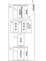
- FIG. 3 shows an example of a functional block diagram of the control device 10.
- the control device 10 includes a reception unit 111, a selection unit 17, a remaining surplus calculation unit 18, and a transmission unit 191.
- the reception unit 111 includes a command acquisition unit 11.
- the remaining surplus calculation unit 18 includes a first calculation unit 181 and a second calculation unit 182.
- the transmission unit 191 includes a power generation suppression control information transmission unit 19.
- a plurality of power generation devices 60 and a plurality of energy storage devices 30 to be managed are registered in the control device 10.
- the control device 10 charges and / or consumes the total surplus output of the plurality of power generation devices 60 to be managed by the plurality of energy storage devices 30 to be managed.
- each power generation device 60 as shown in FIG. 4 is registered in the control device 10 in advance.
- a power generation device ID (Identification) for identifying each of the plurality of power generation devices 60, a rated output (W) of each power generation device 60, and an installation position of each power generation device 60 are associated with each other. Some of these may not be included, and other attribute information may be further registered.
- the rated output (W) here is the inverse of each photovoltaic power generation device determined by the total number of power conditioners and installed solar panels when the power generation device 60 is a photovoltaic power generation device, for example. It is the upper limit of tidal power.
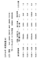
- attribute information (storage related information) of each energy storage device 30 as shown in FIG. 5 is registered in the control device 10 in advance.
- the energy storage device ID for identifying each of the plurality of energy storage devices 30, the type of each energy storage device 30, the rated output (W) of each energy storage device 30, and the rated capacity of each energy storage device 30. (Wh) and address information on the network 50 of the storage control device 20 that controls each energy storage device 30 are associated with each other. Some of these may not be included, and other attribute information may be further registered.
- the types shown in FIG. 5 are classified according to energy storage means, such as storage batteries and heat pump water heaters, types of batteries such as lead storage batteries and lithium ion storage batteries, and charge / discharge response characteristics of storage batteries. Indicates.
- energy storage means such as storage batteries and heat pump water heaters, types of batteries such as lead storage batteries and lithium ion storage batteries, and charge / discharge response characteristics of storage batteries. Indicates.
- the energy storage device 30 registered as a management target is limited to one type (for example, only a lithium ion storage battery), registration of the attribute information is unnecessary.
- the receiving unit 111 receives predetermined information from the external device.
- the command acquisition unit 11 is a command for the power generation device 60 that generates power using natural energy, and acquires a power generation suppression command including a suppression implementation time zone and an upper limit power generation output for each unit time zone (for example, 30 minutes). .
- the command acquisition unit 11 acquires a power generation suppression command for the power generation device 60 to be managed.
- the power generation suppression command may have different contents for each power generation device 60.
- FIG. 6 schematically shows an example of such a power generation suppression command.
- FIG. 6 shows a power generation suppression command for each power generation device 60 (for each power generation device ID).
- the upper limit power generation output for each unit time zone is indicated.
- the upper limit power generation output is shown in units of 30 minutes.
- the upper limit power generation output is indicated by a ratio (%) where the rated output (W) of each power generation device 60 is 100 (%). From the figure, it is understood that the upper limit power generation output in each unit time zone is different for each power generation device 60.
- the suppression implementation time zones of the two power generation devices 60 are the same from 13:00 to 15:00, but the suppression implementation time zones may be different for each power generation device 60. Moreover, the power generation device 60 that has received the power generation suppression command and the power generation device 60 that has not received the power generation suppression command may be mixed in the power generation device 60 to be managed.
- the content of the power generation suppression command may be common to a plurality of power generation devices 60.
- FIG. 7 schematically shows an example of such a power generation suppression command.
- the power generation suppression command is shown without being divided for each power generation device 40.
- the power generation devices 60 that have received the power generation suppression command and the power generation devices 60 that have not received the power generation suppression command may be mixed in the power generation devices 60 to be managed.
- the command acquisition unit 11 acquires information for identifying the power generation device 60 that is the target of the power generation suppression command, in addition to the power generation suppression command as illustrated in FIG. 7.
- zone is made into the unit of 30 minutes, you may make others, such as 1 hour unit, 15 minute unit, 5 minutes, 1 minute unit.
- the upper limit power generation output is shown as a ratio (%) to the rated output of each power generation device 60, but the upper limit output may be indicated by the output value itself (example: 400 kW).
- the power generation suppression command as described above is created, for example, by a transmission / distribution company system (hereinafter also referred to as “transmission / distribution company system”) that manages transmission / distribution of the power system, and is transmitted to a predetermined target person. Since the processing by the power transmission / distribution company system can be realized according to the conventional technology, a detailed description thereof is omitted here, but an outline of an example is as follows.
- the power transmission / distribution company system is based on the next day's attribute information (e.g., weather forecast, date, day of the week, event, etc.) based on the power demand forecast for the next day and the power generation device 60 connected to the power system. Make power generation predictions. And based on these predictions, the necessity of power generation suppression, the time zone in which power generation suppression should be performed, the region to be implemented, the power generation device 60 to be implemented, the total power generation amount to be suppressed (per unit time zone), each power generation The amount of suppression (for each unit time zone) of the device 60 is determined. Then, the power transmission and distribution company system transmits a power generation suppression command to a predetermined target at a predetermined timing (eg, a predetermined time on the previous day).
- a predetermined target e.g, a predetermined time on the previous day.
- the power transmission and distribution company system may be configured to transmit a power generation suppression command for each of the plurality of power generation devices 60 registered in the control device 10 to the control device 10.
- the command acquisition unit 11 receives a power generation suppression command from the power transmission and distribution company system.
- the power transmission and distribution company system may transmit a power generation suppression command to each of the plurality of power generation devices 60.
- the command acquisition unit 11 receives a power generation suppression command from each of the plurality of power generation devices 60 to be managed.
- the selection unit 17 determines a plurality of energy storage devices 30 that execute the surplus absorption process for charging or consuming the total surplus output during the suppression implementation time period.
- the total surplus output (W) is the amount by which the total measured value of the power generation output (W) of each of the plurality of power generation devices 60 exceeds the sum of the upper limit power generation output (W) of each of the plurality of power generation devices 60.
- the upper limit power generation output of each of the plurality of power generation devices 60 is determined based on the power generation suppression command.
- the upper limit power generation output of the power generation device 60 that has received the power generation suppression command is the upper limit power generation output determined by the power generation suppression command.
- the upper limit power generation output of the power generation device 60 that has not received the power generation suppression command is, for example, a rated output.
- the selection unit 17 determines a plurality of energy storage devices 30 that perform the surplus absorption processing.
- all the energy storage devices 30 registered in advance may participate in all surplus absorption processes and execute a process of charging and / or consuming the total surplus output.
- the selection unit 17 determines all the energy storage devices 30 registered in advance as the energy storage devices 30 that execute the surplus absorption process.
- At least a part of the plurality of energy storage devices 30 registered in advance may perform a process of charging and / or consuming the total surplus output by participating in the surplus absorption process.
- the selection unit 17 determines at least a part of the energy storage devices 30 participating in each surplus absorption process from the plurality of energy storage devices 30 registered in advance.
- the concept of “one surplus absorption process” will be described.
- the surplus absorption process (the surplus absorption process from 13:00 to 15:00 in the case of the example in FIG. 6) for one power generation suppression command (for example, the power generation suppression command for the next day shown in FIG. 6) for one time May be treated as
- surplus absorption processes (excess absorption processes from 13:00 to 15:00 in the example of FIG. 6) for one generation suppression instruction (example: power generation suppression instruction for the next day in FIG. 6)
- the surplus absorption process may be divided for each time period, and the surplus absorption process at 13:00 to 14:00 may be treated as one time, and the surplus absorption process at 14:00 to 15:00 may be treated as one time.
- the minimum unit for dividing the time zone is not limited to 30 minutes, and may be 15 minutes, 10 minutes, 1 minute, or a few dozen seconds. As the unit to be divided is made shorter, finer excess absorption processing becomes possible.
- surplus absorption processing for multiple power generation suppression commands may be handled as one time.
- the selection unit 17 determines at least a part of the energy storage devices 30 that participate in each surplus absorption process from the plurality of energy storage devices 30 registered in advance.
- rotation may be determined in advance, and a plurality of energy storage devices 30 may be configured to participate in the surplus absorption process sequentially according to the rotation.
- the selection unit 17 determines at least a part of the energy storage devices 30 that participate in each surplus absorption process based on the rotation.
- a user who manages each of the plurality of energy storage devices 30 may determine the conditions of the surplus absorption process to participate in and register them in the control device 10 in advance.
- Such conditions include, for example, time conditions (eg, participation from March to August, others not participating, etc.), time conditions (eg, participation from 9:00 to 17:00, others not participating, etc.), incentive conditions ( Example: Participation with surplus absorbed power of 5 yen / kWh or more), other conditions (eg, participation if the total time is less than 2 hours, non-participation if it exceeds 2 hours, etc.), but limited to these Not.
- the selection unit 17 determines at least a part of the energy storage devices 30 that match the participation condition from the plurality of energy storage devices 30 registered in advance.
- the selection unit 17 may recruit a user who manages each of the plurality of energy storage devices 30 to participate in the surplus absorption process every time. In this case, the selection unit 17 determines the energy storage device 30 of the user who has announced participation as the energy storage device 30 that participates in each surplus absorption process.
- the recruitment can be performed using communication means such as e-mail, an electronic bulletin board on the network 50, and social media.
- the user who manages each of the plurality of energy storage devices 30 may be able to determine the use conditions of the energy storage device 30 in the surplus absorption process.
- the usage conditions are the upper limit of output (W) that can be used in the surplus absorption process, the upper limit of capacity (Wh) that can be used in the surplus absorption process, etc. (that is, only a part of the output and capacity of the energy storage device 30 is surplus absorption) Participate in the process).
- the usage conditions may be determined for each surplus absorption process.
- the remaining surplus calculation unit 18 determines the remaining surplus output that cannot be charged or consumed by the determined energy storage device 30 based on the power generation suppression command and the content determined by the selection unit 17 before the suppression execution time period. (W) and / or residual surplus power (Wh) is calculated. Specifically, the remaining surplus calculation unit 18 calculates a remaining surplus output (W) and / or a remaining surplus power (Wh) for each unit time zone. Then, the power generation suppression content of the power generation device 60 is determined for each unit time zone.
- the remaining surplus calculation unit 18 calculates the remaining surplus output and / or the remaining surplus electric energy based on the use condition.
- the remaining surplus calculation unit 18 processes by the remaining surplus calculation unit 18 are “a first calculation unit 181 that calculates the total surplus output in the plurality of power generation devices based on the power generation related information and the upper limit power generation output in each of the plurality of power generation devices”, and “ The second surplus power is calculated based on the total surplus output and the storage related information in the plurality of energy storage devices 30 that absorb the total surplus output.
- W residual surplus output
- Wh residual surplus power
- the command acquisition unit 11 acquires a power generation suppression command as shown in FIG. 7 for 10 power generation devices 60 (rated output 500 kW) and 5 power generation devices 60 (rated output 400 kW). To do.
- the upper limit of the total surplus output (W) and the upper limit of the total surplus output amount (Wh) in each unit time zone are calculated.
- a unit time zone from 13:00 to 13:30 will be described as an example.
- the upper limit power generation output in the unit time zone is 80% of the rated output.
- the upper limit of the surplus output in the unit time zone is 20% of the rated output.
- the upper limit of the total surplus output is a value obtained by adding 20% of the rated output of each of the 15 power generation devices 60 that have received the power generation suppression command as shown in FIG.
- the total surplus output amount is a value obtained by multiplying the upper limit of the total surplus output by 0.5 hours corresponding to the unit time zone.
- the maximum upper limit of the total surplus output in the entire suppression implementation time zone is 2100 kW in the unit time zone from 14:00 to 14:30, and the total surplus output amount in the entire suppression implementation time zone It can be seen that the upper limit of 3150 kWh.
- the selection unit 17 uses 200 energy storage devices 30 that can use the output of 5 kW and the capacity of 6 kWh for the surplus absorption process, and the output of 4 kW and the capacity of 5 kWh for the surplus absorption process. Assume that 100 possible energy storage devices 30 have been determined (secured).
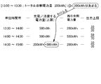
- the remaining surplus calculation unit 18 allocates an available capacity to each unit time zone, for example, as shown in FIG.
- Allocation rules are a matter of design. For example, it may be equally allocated to a plurality of unit time zones, or the operator of the control device 10 may determine how to allocate each time. However, in the case of renewable energy power generation, it is not possible to plan the power generation amount, so it is desirable to refer to the power generation prediction value in advance or to use a method that can reduce the power generation suppression amount stochastically throughout the suppression time zone.
- each power generation device may be individually allocated based on the power generation prediction value of each power generation device 60 and the upper limit power generation output. Specifically, when the power generation prediction value differs for each power generation device 60, the size of the power generation suppression control information is determined based on the amount by which the power generation prediction value for each power generation device 60 exceeds the upper limit power generation output. Also good. That is, a larger power generation suppression burden (a large amount of power generation is suppressed) may be allocated to the power generation apparatus 60 having a relatively large power generation prediction value that exceeds the upper limit power generation output.
- a smaller power generation suppression burden (a small amount of power generation is suppressed) may be allocated to the power generation device 60 having a relatively small power generation prediction value exceeding the upper limit power generation output. Note that the power generation device 60 whose power generation prediction value is relatively smaller than the upper limit power generation output does not receive the power generation suppression control information, or does not need to suppress power generation even if it is received.
- the control device 10 calculates a surplus output that is a power generation output that exceeds the upper limit power generation output using the value of the power generation prediction for each power generation device 60, and in the plurality of power generation devices 60 that the power generation output is equal to or higher than the upper limit power generation output.
- the ratio of the surplus output to the total surplus output may be calculated for each power generation device 60.
- the control apparatus 10 may allocate for every power generation apparatus 60 based on the burden coefficient (ratio) for every power generation apparatus 60 and power generation suppression control information.
- the control apparatus 10 may transmit the electric power generation suppression information which shows the content allocated individually for every electric power generating apparatus 60.
- the amount of power allocated to each unit time zone needs to be equal to or less than the product of “total output of multiple energy storage devices 30” and “time of each unit time zone”.
- the amount of power allocated to each unit time zone needs to be 700 kWh or less, which is the product of 1400 kW (see FIG. 9) and 0.5 hour.
- W residual surplus output
- the allocation is performed so as to satisfy the condition.
- the power generation amount from 13:00 to 14:00 is relatively large, but the power generation amount from 14:00 to 15:00 is relatively small (power generation suppression command (There is also a power source that does not reach the upper limit power generation output due to power generation), and therefore, the situation of the upper limit power generation output due to the power generation suppression command is also taken into consideration, from 13:00 to 13:30, 13:30 to 14:00, and 14 From 0:00 to 14:30, 500 kWh (necessary output 1000 kW) is allocated, and from 14:30 to 15:00, 200 kWh (necessary output 400 kW) is allocated.
- a total of 1000 kW is output by the plurality of energy storage devices 30.
- the total surplus output is charged and / or consumed with the total capacity of 500 kWh as the upper limit of the capacity, and in the unit time zone from 14:30 to 15:00, the total output of 400 kW with the plurality of energy storage devices 30 is the upper limit of the output, This means that the total surplus output is charged and / or consumed with a total capacity of 200 kWh as the upper limit of the capacity.
- the remaining surplus calculation unit 18 calculates the capacity allocated to each unit time zone (the amount of power charged / charged (upper limit)) and the total surplus output for each unit time zone. The difference from the upper limit of the power (see FIG. 8) is calculated as the remaining surplus power amount in each unit time zone.
- the residual surplus calculating unit 18 increases the value of power generation suppression (output suppression) (the value of power generation suppression information is increased) as the residual surplus power and / or the residual surplus power amount (value of residual surplus power information) is large.
- the remaining surplus calculating unit 18 allocates power generation suppression (output suppression) corresponding to the remaining surplus power amount to the plurality of power generation devices 60.
- power generation suppression output suppression
- the rule to allocate is a design matter, you may allocate equally to the several electric power generating apparatus 60.
- power generation suppression (output suppression) for the remaining surplus power may be apportioned by a plurality of power generation devices 60.
- FIG. 9 shows an example in which the ratio of suppression with respect to the rated output is evenly arranged by a plurality of power generators 60.
- the value of “output upper limit” in each unit time zone shown in FIG. 9 indicates the content of power generation suppression (output suppression). This indicates a suppression ratio (output upper limit) with respect to the rated output, and is commonly applied to all the power generation devices 60.
- the output upper limit is set to M (M is a percentage value and 0 ⁇ M ⁇ 1) for ten power generators 60 (see FIG. 8) with a rated output of 500 kW, and similarly, the rated output is 400 kW. Assume that the output upper limit is set to M for the five power generation devices 60. In this case, the maximum amount of power suppressed in the unit time zone is 500 kW ⁇ (1 ⁇ M) ⁇ 10 units ⁇ 0.5 hours + 400 kW ⁇ (1 ⁇ M) ⁇ 5 units ⁇ 0.5 hours. What is necessary is just to calculate M so that this value may become the amount of remaining surplus power in each unit time zone.
- Example 2 An example in which the remaining surplus power (Wh) is mainly generated and power generation suppression (output suppression) for this amount has been described.
- Example 2 an example will be described in which residual surplus output (W) is generated and power generation suppression (output suppression) corresponding to this amount is performed.
- the command acquisition unit 11 acquires power generation suppression commands as shown in FIG. 7 for 10 power generation devices 60 (rated output 500 kW) and 5 power generation devices 60 (rated output 400 kW).
- the upper limit of the total surplus output (W) and the upper limit of the total surplus output amount (Wh) in each unit time zone are calculated.
- the selection unit 17 can use 200 energy storage devices 30 that can use the output of 5 kW and the capacity of 20 kWh for the surplus absorption process, and the output of 4 kW and the capacity of 20 kWh for the surplus absorption process. Assume that 100 energy storage devices 30 are determined (secured).
- the sum (3150 kWh) of the total surplus output amount of the plurality of unit time zones shown in FIG. 8 is equal to or less than the total capacity (6000 kWh) of the energy storage device 30 shown in FIG. That is, a sufficient capacity is secured to charge and / or consume the upper limit of the total surplus output amount.
- the remaining surplus calculation unit 18 calculates the remaining surplus output in the other unit time zone as 0 kW.
- the remaining surplus calculation unit 18 determines the suppression content for performing power generation suppression (output suppression) for the remaining surplus output in the unit time zone from 14:00 to 14:30.
- the rule for allocating power generation suppression (output suppression) for the remaining surplus output to the plurality of power generation devices 60 is a design matter, here, the suppression ratio for the rated output is assumed to be evenly distributed among the plurality of power generation devices 60. .
- the output upper limit is set to M (M is a percentage value and 0 ⁇ M ⁇ 1) for ten power generators 60 (see FIG. 8) with a rated output of 500 kW, and similarly, the rated output is 400 kW. Assume that the output upper limit is set to M for the five power generation devices 60. In this case, the output power to be suppressed is 500 kW ⁇ (1 ⁇ M) ⁇ 10 units + 400 kW ⁇ (1 ⁇ M) ⁇ 5 units. What is necessary is just to calculate M so that this value becomes the remaining surplus output of each unit time zone.
- the suppression ratio for the remaining surplus output and / or the remaining surplus power amount is not made to coincide among the plurality of power generators 60, and the power generation prediction situation for each power generator, etc. In consideration of the above, it may be different for each power generator 60. Even in this case, it is possible to calculate the output upper limit (e.g., the suppression ratio with respect to the rated output) of each power generator 60 by the same concept.
- the transmission unit 191 transmits predetermined information to the external device.
- the power generation suppression control information transmission unit 19 transmits power generation suppression control information for suppressing power generation for the remaining surplus output and / or the remaining surplus power amount to each of the plurality of power generation devices 60.
- the power generation suppression control information may include an upper limit power generation output for each unit time zone of the suppression implementation time zone.
- the power generation suppression control information transmission unit 19 can transmit power generation suppression information before the suppression implementation time period.
- the power generation suppression control information transmission unit 19 uses the output upper limit (eg, the suppression ratio with respect to the rated output; see the output upper limit in FIGS. 9 and 10) for each unit time zone calculated by the remaining surplus calculation unit 18 as a plurality of power generators. 60.
- the output upper limit eg, the suppression ratio with respect to the rated output; see the output upper limit in FIGS. 9 and 10.
- the transmission unit 191 can transmit control information for charging and / or consuming the total surplus output by the energy storage device 30 to the storage control device 20.
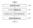
- the command acquisition unit 11 is a command for the power generation device 60 that generates power using natural energy, and acquires a power generation suppression command including a suppression execution time zone and an upper limit power generation output for each unit time zone (S30). .
- the selection unit 17 determines (reserves) a plurality of energy storage devices 30 that perform the surplus absorption process for charging and / or consuming the total surplus output during the suppression implementation time period (S31).
- the remaining surplus calculation unit 18 is based on the power generation suppression command acquired in S30 and the content determined by the selection unit 17 in S31, and the remaining surplus output that cannot be charged and / or consumed by the determined energy storage device 30. (W) and / or remaining surplus power (Wh) is calculated (S32).
- the power generation suppression control information transmission unit 19 transmits power generation suppression control information for suppressing power generation for the remaining surplus output and / or the remaining surplus power amount to each of the plurality of power generation devices 60 (S33).
- the process of S33 may be terminated without being executed, or power generation suppression information indicating that may be transmitted. .
- S30 to S33 The processing of S30 to S33 is performed before the suppression implementation time period specified by the power generation suppression command.
- the power generation device 60 that has received the power generation suppression control information transmitted in S33 performs power generation suppression (output suppression) based on the power generation suppression control information during the suppression execution time period specified by the power generation suppression command.
- the power generation control unit of the power generation device 60 controls the power conditioner based on the power generation suppression control information received from the power generation suppression control information transmission unit 19, and generates power suppression from the power supplied from the power generation element to the power system. Suppressed below the upper limit power generation output specified by the control information.
- the storage control device 20 of FIG. 2 controls the energy storage device 30 according to the control information received from the control device 10, and is charged and / or consumed with predetermined charging power and / or power consumption.
- the details of the processing are design matters, and any configuration can be adopted. An example will be described in the following embodiment.
- the power control system of the present embodiment charges and / or consumes the total surplus output of the plurality of power generation devices 60 distributed over a wide area with the plurality of energy storage devices 30 distributed over a wide area.
- the power control system of the present embodiment charges and / or consumes the total surplus output of the plurality of power generation devices 60 distributed over a wide area with the plurality of energy storage devices 30 distributed over a wide area.
- the power generation device is generated by the amount of power that cannot be charged and / or consumed (estimated or predicted).
- 60 power generation suppression (output suppression) is performed. That is, the energy storage device 30 and the power generation device 60 absorb the total surplus output (charging and / or consumption, power generation suppression (output suppression)).
- the absorption (charging and / or consumption) of the total surplus output by the energy storage device 30 is utilized as much as possible, and only the shortage is supplemented by absorption by the power generation device 60 (power generation suppression (output suppression)).
- the power generation device 60 can be effectively used as much as possible while giving priority to maintaining the supply and demand balance of the power system.
- the control device 10 of the present embodiment can detect the occurrence of an event whose content of the power generation suppression control information should be changed during the suppression execution time zone.
- the control device 10 transmits new power generation suppression control information to the plurality of power generation devices 60 in response to the detection of the event.
- the determined (secured) capacity of the energy storage device 30 can be used without waste.
- the power supply / demand balance of the power system can be maintained appropriately. Details will be described below.
- the configuration of the storage control device 20 and the energy storage device 30 of the power control system of this embodiment is the same as that of the first embodiment.
- configurations of the control device 10 and the power generation device 60 will be described.
- FIG. 12 shows an example of a functional block diagram of the control device 10 of the present embodiment.
- the control device 10 includes a reception unit 111, a selection unit 17, a remaining surplus calculation unit 18, a transmission unit 191, and an event detection unit 16.
- the configurations of the reception unit 111 and the selection unit 17 are the same as those in the first embodiment.
- the event detection unit 16 detects the occurrence of an event whose content of the power generation suppression control information should be changed during the suppression execution time zone.
- the event detecting unit 16 determines that the total surplus output amount in the first unit time zone is the first unit by the remaining surplus calculating unit 18.
- An event (first event) that is less than “the amount of power charged and / or consumed by a plurality of energy storage devices 30 (“the amount of power to be charged and / or consumed (upper limit) ”in FIG. 9)” assigned in the time zone ) Is detected.
- the remaining surplus electric power is generated in each unit time zone, and “in the plurality of energy storage devices 30 determined according to the unit time zone from 13:00 to 13:30”.
- the amount of electric power to be charged and / or consumed is 500 kWh.
- the event detection unit 16 changes the content of the power generation suppression control information. Detect as an event to be performed.
- the event detection unit 16 determines the “amount of power charged and / or consumed by the plurality of energy storage devices 30 in each of the plurality of unit time zones” (“power to be charged and / or consumed in FIG. 9) determined by the remaining surplus calculation unit 18. Information indicating the amount (upper limit) ")" is held in advance. And the event detection part 16 calculates the result of a total surplus output amount based on the measured value of each of the some power generator 60 for every unit time slot
- the event detection unit 16 monitors the state of the communication path from the control device 10 to the storage control device 20 and the state of the energy storage device 30 (full charge or depletion state of the storage battery, SOC value, etc.), and implements suppression.
- the energy storage device 30 is used for another purpose, such as a communication failure, a significant communication delay, an abnormal rise in the temperature of the energy storage device 30, an overcurrent, or a voltage abnormality during the time period. Detecting an event (second event) in which a part of the plurality of energy storage devices 30 determined by the selection unit 17 cannot execute the surplus absorption process due to the loss of the energy storage capacity due to the influence such as Also good. Other causes of the inability to perform the surplus absorption process may be, for example, a failure of the energy storage device 30, but are not limited thereto.
- the event detection unit 16 may acquire a signal indicating the occurrence of the second event from, for example, a monitoring device that monitors the operation of the energy storage device 30 that is executing the surplus absorption process.
- a monitoring device that monitors the operation of the energy storage device 30 that is executing the surplus absorption process.
- the operator of the control device 10 may input the signal to the control device 10.
- the event detection part 16 may detect a 2nd event by acquisition of the said signal.
- each storage control device 20 may have the monitoring device.
- the remaining surplus calculating unit 18 recalculates the remaining surplus output and / or the remaining surplus electric power according to the event detection by the event detecting unit 16. Then, the remaining surplus calculation unit 18 re-determines the power generation suppression content for each of the plurality of power generation devices 60 based on the result.
- the remaining surplus calculation unit 18 has a plurality of energies in a unit time zone in which the first event occurs (hereinafter, “first unit time zone”). Based on the amount of power determined to be charged and / or consumed by the storage device 30 (“charged and / or consumed power (upper limit)” in FIG. 9), the total surplus output amount in the first unit time zone is obtained. The subtracted value (hereinafter “unused capacity”) is calculated.
- the remaining surplus calculation unit 18 allocates the unused capacity in a unit time zone after the first unit time zone. For example, you may allocate to the unit time slot
- the amount of power determined to be charged and / or consumed by the plurality of energy storage devices 30 in a predetermined unit time zone (“the amount of power to be charged and / or consumed (upper limit)” in FIG. 9) is allocated. Increase by a certain amount. In this way, the remaining surplus calculation unit 18 re-determines the amount of power to be charged and / or consumed by the plurality of energy storage devices 30 for each unit time zone.
- the remaining surplus calculation unit 18 determines the power generation suppression content of the plurality of power generation devices 60 according to the newly calculated remaining surplus power amount in each unit time zone. The method of determining the power generation suppression content of the plurality of power generation devices 60 according to the remaining surplus power is as described above.
- the remaining surplus calculation unit 18 determines the amount of power to be charged and / or consumed by the plurality of energy storage devices 30 in each of the plurality of unit time zones as shown in FIG. 9 before the suppression implementation time zone. To do. That is, 500 kWh is determined in the unit time zone from 13:00 to 13:30, 13:30 to 14:00, and 14:00 to 14:30, and from 14:30 to 15:00 In the unit time zone, 200 kWh is determined.
- the remaining surplus calculation unit 18 allocates 300 kWh of power in the unit time zone from 14:30 to 15:00.
- the electric energy determined to be charged and / or consumed by the plurality of energy storage devices 30 in the unit time zone is 500 kWh
- the remaining surplus electric energy is 200 kWh.
- the residual surplus calculation part 18 grasps
- the power generation suppression control information transmission unit 19 outputs a plurality of newly determined power generation suppression control information according to recalculation of the residual surplus output and / or the residual surplus power amount by the residual surplus calculation unit 18. It transmits to each power generator 60.
- Used capacity occurs when the total capacity of the determined (reserved) energy storage devices 30 is insufficient and the remaining surplus power is generated, by effectively utilizing such unused capacity, the power generator 60 can be made more effective. Can be used effectively. Since the first event is detected, the power generation suppression amount can be reduced.
- the power generation device 60 can be used more effectively.
- the power generation suppression contents for the plurality of power generation devices 60 can be reviewed.
- the power generation suppression amount of each of the plurality of power generation devices 60 can be changed to increase. As a result, it is possible to reduce the disadvantage of excessive power supply to the power system. Since the 2nd event was detected, it can change in the direction which increases power generation suppression amount.
- ⁇ Third Embodiment> configuration examples of the storage control device 20 and the energy storage device 30 will be described. Specifically, a specific example of processing for charging and / or consuming the total surplus output of the plurality of power generation devices 60 will be described. In addition, according to this embodiment, the time lag between the timing when the surplus output is reversely flowed from the power generation device 60 to the power system and the timing when the energy storage device 30 charges / consumes the surplus output can be reduced. . This will be described below.
- the configuration of the power generation device 60 is the same as in the first and second embodiments.
- the control device 10 includes a reception unit 111, a surplus calculation unit 12, a burden coefficient determination unit 13, a selection unit 17, a remaining surplus calculation unit 18, and a transmission unit 191.
- FIG. The reception unit 111 includes a command acquisition unit 11.
- the transmission unit 191 includes a surplus notification unit 14, a burden coefficient notification unit 15, and a power generation suppression control information transmission unit 19.
- the remaining surplus calculation unit 18 includes a first calculation unit 181 and a second calculation unit 182.
- the surplus notification part 14, the burden coefficient notification part 15, and the power generation suppression control information transmission part 19 can communicate via the same communication part.
- the configurations of the reception unit 111, the event detection unit 16, the selection unit 17, the remaining surplus calculation unit 18, and the power generation suppression control information transmission unit 19 are the same as those in the first and second embodiments.
- the burden coefficient determination unit 13 determines a burden coefficient indicating the burden ratio of the surplus absorption process corresponding to each of the plurality of energy storage devices 30 determined as the apparatus that executes the surplus absorption process by the selection unit 17.
- the burden coefficient determination unit 13 determines the burden coefficient before the surplus absorption process is started. For example, the burden coefficient determination unit 13 determines the burden coefficient by the following method.
- a user who manages each of the plurality of energy storage devices 30 can determine the use conditions of the energy storage device 30 in the surplus absorption process.
- the usage conditions include an output upper limit (W) that can be used in the surplus absorption process, a capacity upper limit (Wh) that can be used in the surplus absorption process, and the like.
- the burden coefficient determination unit 13 determines the burden coefficient based on, for example, such usage conditions and the design of each energy storage device 30 (see FIG. 5). For example, a burden coefficient that is a heavier burden ratio, that is, a larger burden coefficient is determined for the energy storage device 30 having a large available output upper limit and a usable capacity upper limit.
- the specific calculation method is a design matter.
- the burden coefficient indicates the burden ratio of each energy storage device 30 with respect to the total surplus output.
- the burden coefficient may be expressed as a percentage. In the case of this example, for example, the energy storage device 30 for which a burden coefficient of “0.05” is determined is charged and / or consumed at an output of 5% of the total surplus output during the surplus absorption process.
- the burden coefficient may be a value obtained by standardizing the above percentage value. For example, a value obtained by multiplying the percentage value by a predetermined value N (a value equal to or greater than the upper limit value of the total surplus output (W)) may be used as the burden coefficient.
- the burden coefficient determination unit 13 can determine a burden coefficient for each unit time zone of the suppression implementation time zone.
- the burden coefficient notification unit 15 transmits the burden coefficient of each energy storage device 30 determined by the burden coefficient determination unit 13 to each of the plurality of storage control devices 20 that control the operation of each energy storage device 30.
- the burden coefficient may be transmitted in association with information capable of identifying a surplus absorption process in which the burden coefficient is effective. For example, it may be transmitted in association with an effective period or time, such as “December 4, 2015, 13:00 to 15:00”.
- the transmission timing of the burden coefficient is an arbitrary timing after the determination by the burden coefficient determination unit 13 and before the start of the surplus absorption process.
- the burden coefficient notification unit 15 sequentially transmits a burden coefficient having contents corresponding to each energy storage device 30 to each of the plurality of storage control devices 20.
- the surplus calculation unit 12 repeatedly calculates the total surplus output based on the actual power generation value of each of the plurality of power generation devices 60 during the suppression implementation time period.
- the total surplus output (W) is the amount by which “the total of the measured values of the power generation outputs (W) of each of the plurality of power generation devices 60” exceeds “the total of the upper limit power generation output (W) of each of the plurality of power generation devices 60”. is there.
- FIG. 20 shows an example of a functional block diagram of the surplus calculation unit 12.
- the surplus calculation unit 12 includes a first addition unit 121, a subtraction unit 122, a specification unit 123, and a second addition unit 124.
- the receiving unit 111 receives power generation related information (power generation output: actual measurement value) regarding each power generation state from each of the plurality of power generation devices 60 for each predetermined period T1a.
- power generation related information power generation output: actual measurement value
- each of the plurality of power generation devices 60 obtains data on the power generation output (instantaneous value (W)) of each power generation device 60 measured at a predetermined time interval (for example, 400 msec) by real-time processing during the suppression execution time zone. Get repeatedly. And each of the some electric power generating apparatus 60 transmits the said measured value to the control apparatus 10 repeatedly with the period T1a (example: 10 sec) longer than the said time interval. For example, the power generation device 60 transmits representative values (eg, average value, maximum value, minimum value, mode value, intermediate value, etc.) of a plurality of measurement values obtained during the period T1a to the control device 10. .
- representative values eg, average value, maximum value, minimum value, mode value, intermediate value, etc.
- the plurality of power generation devices 60 transmit the measurement values to the control device 10 while shifting the timing by a time smaller than the period T1a in order to prevent the transmission data from being congested.
- the first adding unit 121 acquires the power generation related information received by the receiving unit 111. Then, the first addition unit 121 calculates the sum of the power generation outputs (actually measured values) of the plurality of power generation devices 60. The first addition unit 121 repeatedly calculates, for example, “the sum of the power generation outputs (measured power generation actual values) by each of the plurality of power generation devices 60” in the same cycle as the cycle T1a.
- the specifying unit 123 acquires the power generation suppression command acquired by the command acquisition unit 11. Thereafter, the specifying unit 123 specifies the upper limit power generation output (W) of each power generation device 60.
- the upper limit power generation output of the power generation device 60 that has received the power generation suppression command is the upper limit power generation output determined by the power generation suppression command.
- the upper limit power generation output of the power generation device 60 that has not received the power generation suppression command is, for example, a rated output.
- the second addition unit 124 calculates the sum of the upper limit power generation outputs of the plurality of power generation devices 60.
- the specifying unit 123 may specify the upper limit power generation output of each of the plurality of power generation devices 60 for each unit time zone defined by the power generation suppression command. And the 2nd addition part 124 may calculate "the total of the upper limit electric power generation output of each of the some electric power generating apparatus 60" for every unit time slot
- the subtraction unit 122 calculates the sum of the power generation outputs (actually measured values) of the plurality of power generation devices 60 calculated by the first addition unit 121 and the sum of the upper limit power generation outputs of the plurality of power generation devices 60 calculated by the second addition unit 124.
- the difference (total surplus output) is repeatedly calculated at a predetermined cycle T1.
- the subtraction unit 122 calculates “the plurality of power generation devices 60 in the corresponding time zone”.
- the total surplus output is calculated using the “total of the upper limit power generation output by each”.
- the surplus notification unit 14 repeatedly transmits surplus output information indicating the total surplus output to the plurality of storage control devices 20 during the suppression execution time period.
- the surplus output information may be a value of the total surplus output (W) itself calculated by the surplus calculation unit 12 or may be a value obtained by standardizing the value. For example, the value obtained by dividing the total surplus output (W) by a predetermined value N (a value equal to or greater than the upper limit value of the total surplus output (W). For example, the total rated output of all the power generation devices 60 to be suppressed-the maximum upper limit power output). May be a normalized value.
- the predetermined value N is the same value as the predetermined value N used for normalization of the burden coefficient described above.
- the surplus notification unit 14 repeatedly transmits surplus output information indicating the total surplus output repeatedly calculated by the surplus calculation unit 12 in the cycle T1 to the storage control device 20 in the same cycle.
- the surplus notification unit 14 can simultaneously transmit surplus output information to the storage control device 20.
- the present invention is not limited thereto.
- FIG. 15 shows an example of a functional block diagram of the storage control device 20.
- the storage control device 20 includes a burden coefficient receiving unit 21, a surplus receiving unit 22, a charging power determining unit 23, and an operation control unit 24.
- the burden coefficient receiving unit 21 and the surplus receiving unit 22 can communicate via the same communication unit.
- FIG. 21 shows another example of a functional block diagram of the storage control device 20.
- the storage control device 20 shown in the figure includes a load coefficient receiving unit 21, a surplus receiving unit 22, a charging power determination unit 23, an operation control unit 24, and a monitoring device 25.
- the burden coefficient receiving unit 21 receives the burden coefficient individually transmitted by the burden coefficient notification unit 15 to each of the plurality of storage control devices 20 before the start of the surplus absorption process.
- the surplus receiving unit 22 receives surplus output information simultaneously transmitted by the surplus notification unit 14 to the plurality of storage control devices 20 during the suppression implementation time period.
- the surplus receiving unit 22 repeatedly receives surplus output information repeatedly transmitted by the surplus notifying unit 14 in the cycle T1.
- the charging power determining unit 23 is an energy storage device that charges and / or consumes the power of the total surplus output based on the burden coefficient received by the burden coefficient receiving unit 21 and the latest surplus output information received by the surplus receiving unit 22. 30 charging powers and / or power consumption are determined. When the surplus receiving unit 22 repeatedly receives surplus output information, the charging power determining unit 23 repeatedly determines charging power and / or power consumption accordingly.
- the burden coefficient is a percentage (for example, “0.05”) indicating the burden ratio of each energy storage device 30 with respect to the total surplus output
- the surplus output information is the value (W) of the total surplus output itself.
- the charging power determination unit 23 can determine the product of the total surplus output and the burden coefficient as charging power (W) / power consumption (W).
- the charging power determination unit 23 charges the product of the information indicating the total surplus output (value obtained by normalizing the total surplus output) and the burden coefficient. It can be determined as power (W) / power consumption (W).
- the operation control unit 24 controls the energy storage device 30 to execute the surplus absorption process during the suppression implementation time period.
- the operation control unit 24 causes the energy storage device 30 to charge and / or consume the charging power and / or power consumption determined by the charging power determination unit 23.
- the charging power determination unit 23 repeatedly determines charging power and / or power consumption during the suppression execution time period.
- the operation control unit 24 causes the energy storage device 30 to charge and / or consume with the newly determined charging power and / or power consumption.
- the monitoring device 25 acquires (detects and measures) state information indicating the state of the energy storage device 30 and repeatedly transmits it to the control device 10.
- the state information is, for example, SOC, free capacity (Wh), charge amount (Wh), voltage, current, temperature, energy storage amount, error information, and the like.
- the power transmission / distribution company system is, for example, based on the next day's attribute information (eg, weather forecast, date, day of the week, event, etc.), the power demand forecast for the next day and the power generator connected to the power system Power generation prediction by 60 is performed. And based on these predictions, the necessity of power generation suppression, the time zone in which power generation suppression should be performed, the region to be implemented, the power generation device 60 to be implemented, the total amount to be suppressed (per unit time zone), each power generation device 60 suppression amounts (per unit time zone) and the like are determined. Then, the power transmission and distribution company system transmits a power generation suppression command for the next day to a predetermined target at a predetermined timing (eg, a predetermined time on the previous day).
- a predetermined target eg, a predetermined time on the previous day.
- the power generation suppression command includes the suppression implementation time zone and the upper limit power generation output for each unit time zone (see FIGS. 6 and 7).
- the power transmission and distribution company system transmits to the control device 10 power generation suppression commands for the plurality of power generation devices 60 registered in the control device 10.
- the power transmission and distribution company system determines whether the power generation suppression command is a target of the power generation suppression command. Information for identifying the power generation device 60 is transmitted to the control device 10.
- the power transmission and distribution company system may transmit a power generation suppression command to each of the plurality of power generation devices 60 subject to power generation suppression.
- a power generation suppression command is transmitted from each of the power generation devices 60 to the control device 10, whereby the control device 10 grasps the contents of the power generation suppression command.
- control device 10 determines the energy storage device 30 that participates in the surplus absorption process for the power generation suppression command acquired in S10.
- the specific example of the process to determine is as above-mentioned.
- control device 10 may invite a user who manages each of the plurality of registered energy storage devices 30 to participate in the surplus absorption process. And the control apparatus 10 may determine the energy storage apparatus 30 of the user who announced participation as the energy storage apparatus 30 which participates in a surplus absorption process. Note that the order of S10 and S11 may be switched.
- control device 10 determines the remaining surplus output and / or the remaining surplus power that cannot be charged and / or consumed by the determined energy storage device 30 based on the power generation suppression command acquired in S10 and the content determined in S11. Is calculated. A specific example of the calculation process is as described above.
- control device 10 when there is a remaining surplus output and / or a remaining surplus power amount, the control device 10 generates power generation suppression control information for suppressing power generation for the calculated remaining surplus output and / or remaining surplus power amount. Generate for each.
- a specific example of this processing is as described above.
- the control device 10 determines a burden coefficient for each energy storage device 30 determined in S11.
- a specific example of the process for determining the burden coefficient is as described above.
- the control apparatus 10 can determine the burden coefficient of each of the some storage control apparatuses 20 for every unit time slot
- control device 10 transmits the power generation suppression control information generated in S12 to each of the plurality of power generation devices 60.
- the control device 10 may notify the plurality of power generation devices 60 of the suppression execution time zone.
- the control device 10 When the remaining surplus output and / or the remaining surplus power is “0”, the control device 10 does not have to transmit the power generation suppression control information in S14. Alternatively, power generation suppression control information indicating that the remaining surplus output and / or the remaining surplus power amount is “0” may be transmitted.
- control device 10 transmits the burden coefficient of each of the plurality of energy storage devices 30 determined in S13 to the storage control device 20 that controls each of the energy storage devices 30 to be controlled.
- S15 is preferably performed before the suppression implementation time zone, but may be performed at the beginning of the suppression implementation time zone. S15 may determine a burden coefficient (may be the same coefficient) for a plurality of suppression time zones when a power generation suppression command is received for each suppression time zone (every minute or every few seconds) in real time.
- each of the plurality of power generation devices 60 performs power generation suppression (output suppression) based on the power generation suppression control information.
- the power generation device 60 performs the suppression. Even during the time period, power generation is continued without power generation suppression (output suppression).
- each of the plurality of power generation devices 60 repeatedly transmits the power generation actual measurement value (instantaneous value (W)) of the power generation device 60 to the control device 10 in a cycle T1.
- the output (W) of the power generator 60 is measured at a measurement interval (eg, 400 msec) smaller than the cycle T1, and a representative value (eg, an average value) of a plurality of measured values (W) obtained during the cycle T1.
- the maximum value, the minimum value, the mode value, the intermediate value, the integrated value during the period T1, etc.) are transmitted to the control device 10.
- the plurality of power generation devices 60 transmit measured power generation values while shifting the timing by a time smaller than the period T1 in order to prevent the transmission data from being congested.
- control device 10 repeatedly calculates the total surplus output in the cycle T1.
- the total surplus output is calculated based on the actual power generation value of each of the plurality of power generation devices 60 repeatedly acquired in S16.
- the method for calculating the total surplus output is as described above.
- control device 10 repeatedly transmits the surplus output information indicating the total surplus output to the plurality of storage control devices 20 in the period T1.
- the control device 10 can simultaneously transmit the surplus output information to the plurality of storage control devices 20 using means such as multicast.
- each of the plurality of storage control devices 20 charges each storage control device 20 in the surplus absorption process based on the burden coefficient received in S15 and the surplus output information (latest surplus output information) received repeatedly in S18.
- the power and / or power consumption is determined repeatedly.
- the storage control device 20 determines new charge power and / or power consumption based on the new surplus output information.
- the burden coefficient is a percentage (for example, “0.05”) indicating the burden ratio of each energy storage device 30 with respect to the total surplus output
- the surplus output information is the value (W) of the total surplus output itself.
- the charging power determination unit 23 can determine the product of the total surplus output and the burden coefficient as charging power (W) / power consumption (W).
- the storage control device 20 uses the burden coefficient of the unit time slot corresponding to the current time to calculate the charging power and / or the power consumption. decide.
- each of the plurality of storage control devices 20 controls each of the plurality of energy storage devices 30 so as to be charged and / or consumed with the latest charging power and / or power consumption determined in S19.
- the control device 10 acquires a power generation suppression command.
- the control device 10 has acquired a power generation suppression command as shown in FIG. 7 for ten power generation devices 60 with a rated output of 500 kW and five power generation devices 60 with a rated output of 400 kW.
- the upper limit of the total surplus output (W) and the upper limit of the total surplus output amount (Wh) in each unit time zone are calculated. The calculation method is as described above.
- the control device 10 determines the energy storage device 30 that participates in the surplus absorption process for the power generation suppression command.
- 200 energy storage devices 30 that can use an output of 5 kW and a capacity of 6 kWh by surplus absorption processing and 100 energy storage devices 30 that can use an output of 4 kW and a capacity of 5 kWh by surplus absorption processing are determined.
- the determined total output of the plurality of energy storage devices 30 is 1400 kW, and the total capacity is 1700 kWh.
- the control device 10 calculates the remaining surplus output and / or the remaining surplus power for each unit time zone. In addition, when there is a remaining surplus output and / or a remaining surplus power amount, the control device 10 generates power generation suppression control information for suppressing power generation for the calculated remaining surplus output and / or remaining surplus power amount. Generate for each. Here, it is assumed that it is calculated and determined as shown in FIG. The calculation and determination method is as described above.
- the control device 10 calculates a burden coefficient for each of the plurality of energy storage devices 30.
- the burden ratios of the determined 300 energy storage devices 30 are equalized.
- the burden ratio (percentage) of each of the 300 energy storage devices 30 is 1/300.
- this value may be used as the burden coefficient, here, a value obtained by standardizing the value is used as the burden coefficient.
- FIG. 17 shows a standard value obtained by multiplying the burden ratio (percentage) by the upper limit of the total surplus output (W) for each unit time zone as a burden coefficient for each unit time zone.
- a different burden coefficient may be determined for each energy storage device 30.
- control device 10 transmits the power generation suppression control information to the plurality of power generation devices 60 based on the content determined in S12.
- the output upper limit ratio to the rated output for each unit time zone shown in FIG. 9 is transmitted.
- control device 10 transmits the burden coefficient determined in S13 to each of the plurality of storage control devices 20.
- the power generation device 60 performs power generation suppression (output suppression) based on the power generation suppression control information received in S14.
- the power generation device 60 that has acquired the output upper limit (ratio to the rated output) for each unit time zone shown in FIG. 9 controls the output for each unit time zone to be equal to or lower than the output upper limit shown in FIG.
- each of the plurality of power generation devices 60 repeatedly transmits the power generation actual measurement value (instantaneous value (W)) to the control device 10 in the cycle T1.
- control device 10 repeatedly calculates the total surplus output in the cycle T1 based on the data received in S16.
- the control device 10 transmits surplus output information related to the total surplus output.
- the control device 10 transmits, as surplus output information, a value (standardized value) obtained by dividing the total surplus output calculated in S17 by the total surplus output upper limit (see FIG. 17) of each unit time zone.
- the control device 10 can simultaneously transmit the surplus output information to the plurality of storage control devices 20 using means such as multicast.
- each of the plurality of storage control devices 20 charges each storage control device 20 in the surplus absorption process based on the burden coefficient received in S15 and the surplus output information (latest surplus output information) received repeatedly in S18. Determine power and / or power consumption. Specifically, the storage control device 20 determines the product of the normalized burden coefficient and the normalized total surplus output (surplus output information) as charging power and / or power consumption. Each time the storage control device 20 acquires new surplus output information, the storage control device 20 determines new charge power and / or power consumption based on the new surplus output information.
- each of the plurality of storage control devices 20 controls each of the plurality of energy storage devices 30 so as to be charged and / or consumed with the latest charging power and / or power consumption determined in S19.
- the power control system of the present embodiment includes a power generation side device group (power generation device 60 and the like) distributed in a wide area, a server (control device 10), and a charging and / or consumption side distributed in a wide area. And a device group (storage control device 20, energy storage device 30 and the like).
- a measurement / communication delay ⁇ t1 occurs due to measurement of each of the plurality of power generation side devices and data transmission from each to the server.
- a processing delay ⁇ t2 due to calculation processing at the server occurs.
- a communication / response delay ⁇ t3 occurs due to data transmission from the server to a plurality of charging and / or consuming devices.
- the time lag between the timing when the surplus output is reversely flowed from the power generation device 60 to the power system and the timing when the energy storage device 30 charges and / or consumes the surplus output increases.
- the communication / response delay ⁇ t3 can be reduced. This will be described below.
- control device 10 (server) determines the burden coefficient of each of the plurality of energy storage devices 30 before the suppression implementation time period, and the plurality of storage control devices 20 (charging and / or consumption side devices). Group) send to each. In the suppression execution time zone, the control device 10 repeatedly transmits the same data (surplus output information) to the plurality of storage control devices 20.
- the burden coefficient is transmitted before the suppression implementation time zone, it is not related to the communication / response delay ⁇ t3. Further, since the contents of the surplus output information transmitted to the plurality of storage control devices 20 are the same, the control device 10 can simultaneously transmit the surplus output information to the plurality of storage control devices 20. As a result, the communication / response delay ⁇ t3 can be reduced as compared with the case where predetermined data is sequentially transmitted to the plurality of storage control devices 20 one after another.
- the processing delay ⁇ t2 can be reduced. This will be described below.
- control device 10 performs “arithmetic processing for calculating the total surplus output based on the actual power generation measurement value”, and each of the plurality of storage control devices 20 performs “each energy storage device based on the calculated total surplus output”. 30 arithmetic operations for determining charging and / or power consumption ”.
- the “arithmetic processing for determining charging and / or power consumption of each energy storage device 30 based on the calculated total surplus output” is shared by the plurality of storage control devices 20.
- Each of the plurality of storage control devices 20 determines only charging and / or power consumption of the corresponding energy storage device 30. For this reason, the said arithmetic processing can be divided for every energy storage device 30, and can be advanced in parallel.
- the processing delay ⁇ t2 can be reduced as compared with the case where the control device 10 performs both arithmetic processes.
- charging and / or power consumption of each energy storage device 30 can be determined by a simple calculation of multiplying the burden coefficient and the value indicated by the surplus output information. For this reason, the increase in the delay which generate
- the power control system of the present embodiment realizes further reduction of the processing delay ⁇ t ⁇ b> 2 described with reference to FIG. 18 by the characteristic configuration of the control device 10 and the power generation device 60.
- Other configurations such as the storage control device 20 and the energy storage device are the same as those in the third embodiment.
- configurations of the power generation device 60 and the control device 10 will be described.
- Each of the plurality of power generation devices 60 acquires a power generation suppression command.
- the control device 10 may transmit the power generation suppression command acquired from the power transmission and distribution company system to each power generation device 60.
- the power transmission / distribution company system may transmit a power generation suppression command to each power generation device 60. In any case, the transmission is performed before the suppression implementation time period.
- Each of the plurality of power generation devices 60 repeats the surplus output (W) during the suppression execution time zone based on the actual power generation value (W) and the upper limit power generation output (W) for each unit time zone specified by the power generation suppression command. calculate.
- the surplus output is an output portion greater than or equal to the upper limit power generation output in the power generation actual measurement value.
- the actual measurement value of the power generation output of each power generation device 60 is a value less than the upper limit power generation output of each power generation device 60
- the difference from the upper limit power generation output is calculated as a negative value to obtain a negative surplus output.
- each of the plurality of power generation devices 60 repeatedly measures the power generation output (instantaneous value (W)) at a predetermined measurement interval (eg, 400 msec) during the suppression implementation time period. And each of the some electric power generating apparatus 60 calculates a surplus output repeatedly based on a measured value. Each of the plurality of power generation devices 60 repeats the calculated surplus output to the control device 10 at a period T1 (eg, a time interval (several seconds) longer than the measurement interval or the same time interval as the measurement interval). Send.
- a period T1 eg, a time interval (several seconds) longer than the measurement interval or the same time interval as the measurement interval.
- the power generation device 60 represents the representative values (eg, average value, maximum value, minimum value, mode value) of a plurality of measurement values obtained during the period T1. , Intermediate value, integrated value during the period T1, etc.) may be used to calculate the surplus output to be transmitted to the control device 10.
- representative values eg, average value, maximum value, minimum value, mode value
- FIG. 23 shows an example of a functional block diagram of the power generation device 60.
- the receiving unit 601 receives a power generation suppression command.
- the subtraction unit 602 repeatedly calculates the surplus output by subtracting the upper limit power generation output from the power generation result value.
- the upper limit power generation output is specified based on the power generation suppression command.
- the transmission unit 603 repeatedly transmits the surplus output calculated by the subtraction unit 602 to the control device 10.
- FIG. 14 An example of a functional block diagram of the control device 10 is shown in FIG. 14 as in the third embodiment.
- the control device 10 includes a reception unit 111, a surplus calculation unit 12, a burden coefficient determination unit 13, a selection unit 17, a remaining surplus calculation unit 18, and a transmission unit 191. Furthermore, you may have the event detection part 16.
- FIG. The reception unit 111 includes a command acquisition unit 11.
- the transmission unit 191 includes a surplus notification unit 14, a burden coefficient notification unit 15, and a power generation suppression control information transmission unit 19.
- the remaining surplus calculation unit 18 includes a first calculation unit 181 and a second calculation unit 182.
- the surplus notification part 14, the burden coefficient notification part 15, and the power generation suppression control information transmission part 19 can communicate via the same communication part.
- the configurations of the reception unit 111, the event detection unit 16, the selection unit 17, the remaining surplus calculation unit 18, the power generation suppression control information transmission unit 19, the burden coefficient determination unit 13, the surplus notification unit 14, and the burden coefficient notification unit 15 are first to thru. This is the same as in the third embodiment.
- the surplus calculation unit 12 receives information indicating a surplus output from each of the plurality of power generation devices 60. Then, the surplus calculation unit 12 calculates the total surplus output by adding the surplus outputs of each of the plurality of power generation devices 60.
- the same operational effects as those of the first to third embodiments can be realized. Further, according to the present embodiment, the processing delay ⁇ t2 described with reference to FIG. 18 can be reduced.
- each of the plurality of power generation devices 60 performs “processing for calculating surplus output of each power generation device 60”, and the control device 10 performs “processing for adding the surplus outputs of each power generation device 60”. That is, the “processing for calculating the surplus output of each power generation device 60” is shared by the plurality of power generation devices 60.
- the processing delay ⁇ t2 can be reduced as compared with the case where the control device 10 performs both arithmetic processes.
- the control device 10 predicts the total surplus output for the next period based on the past total surplus output, and transmits the predicted total surplus output to the plurality of storage control devices 20.
- Have Other configurations such as the storage control device 20, the energy storage device 30, and the power generation device 60 are the same as those in the first to fourth embodiments.
- FIG. 14 An example of a functional block diagram of the control device 10 is shown in FIG. 14 as in the third and fourth embodiments.
- the control device 10 includes a reception unit 111, a surplus calculation unit 12, a burden coefficient determination unit 13, a selection unit 17, a remaining surplus calculation unit 18, and a transmission unit 191. Furthermore, you may have the event detection part 16.
- FIG. The reception unit 111 includes a command acquisition unit 11.
- the transmission unit 191 includes a surplus notification unit 14, a burden coefficient notification unit 15, and a power generation suppression control information transmission unit 19.
- the remaining surplus calculation unit 18 includes a first calculation unit 181 and a second calculation unit 182.
- the surplus notification part 14, the burden coefficient notification part 15, and the power generation suppression control information transmission part 19 can communicate via the same communication part.
- the configurations of the reception unit 111, the event detection unit 16, the selection unit 17, the remaining surplus calculation unit 18, the power generation suppression control information transmission unit 19, the burden coefficient determination unit 13, and the burden coefficient notification unit 15 are the first to fourth embodiments. It is the same.
- the surplus calculation unit 12 calculates a predicted value of the total surplus output of the next period based on the newly calculated total surplus output and the total surplus output calculated before that.
- the surplus calculation unit 12 can employ any prediction method.
- a prediction model may be created. Then, the estimated value may be obtained by inputting time series data in which the N total surplus outputs including the newly calculated total surplus output are arranged in the calculation order to the prediction model.
- a linear expression (prediction) in a graph with time on the horizontal axis and total surplus output on the vertical axis Formula) may be calculated. Then, an estimated value may be obtained by inputting the time t2 at the next cycle to the linear equation.
- the surplus notification unit 14 replaces the total surplus output calculated by the surplus calculation unit 12 with the predicted value of the total surplus output of the next period calculated based on the total surplus output calculated by the surplus calculation unit 12 as surplus output information. It transmits to the plurality of storage control devices 20.
- the control device 10 can estimate the total surplus output for the next period and notify the storage control device 20 of it.
- the surplus output is estimated for the total value of the plurality of power generators 60, a leveling effect can be expected, and a rapid output fluctuation can be mitigated. As a result, it is possible to estimate the surplus output more accurately.
- the problem of the time lag between the timing when the surplus output is supplied from the power generation device 60 to the power system and the timing when the surplus output is charged and / or consumed by the energy storage device 30 can be reduced, and the supply-demand balance accompanying the time lag. Can be sufficiently reduced.
- the processing delay ⁇ t2 and the communication / response delay ⁇ t3 can be reduced as described in these embodiments. For this reason, the period from the measurement of the output of the power generation device 60 to the charging of the energy storage device 30 and / or the determination of the power consumption based on the measurement value can be reduced. As a result, it becomes easier to predict the total surplus output for the next period, and the estimation accuracy can be improved.
- the control device 10 of the power control system of the present embodiment repeatedly acquires information indicating the state of each of the plurality of energy storage devices 30 during the suppression implementation time period, and based on the information, the burden on each of the plurality of energy storage devices 30.
- the coefficient is determined repeatedly.
- the control device 10 repeatedly transmits the repeatedly determined burden coefficient to each storage control device 20. Since the burden coefficient redetermination process requires a sufficiently long calculation time, the period Ta for transmitting the burden coefficient is the period Tb for transmitting surplus output information (described in the third to fifth embodiments). Longer than the cycle T1).
- the configurations of the energy storage device 30 and the power generation device 60 are the same as those in the first to fifth embodiments.
- the control device 10 includes a reception unit 111, a surplus calculation unit 12, a burden coefficient determination unit 13, a selection unit 17, a remaining surplus calculation unit 18, and a transmission unit 191. Furthermore, you may have the event detection part 16.
- FIG. The reception unit 111 includes a command acquisition unit 11.
- the transmission unit 191 includes a surplus notification unit 14, a burden coefficient notification unit 15, and a power generation suppression control information transmission unit 19.
- the remaining surplus calculation unit 18 includes a first calculation unit 181 and a second calculation unit 182.
- the burden coefficient determination unit 13 includes an acquisition unit 131.
- the surplus notification part 14, the burden coefficient notification part 15, and the power generation suppression control information transmission part 19 can communicate via the same communication part.
- the configurations of the reception unit 111, the event detection unit 16, the selection unit 17, the remaining surplus calculation unit 18, the power generation suppression control information transmission unit 19, the surplus calculation unit 12, and the surplus notification unit 14 are the same as those in the first to fifth embodiments. It is.
- the burden factor determination unit 13 repeatedly determines the burden factor of each of the plurality of energy storage devices 30 during the suppression implementation time period (while the energy storage device 30 is performing the absorption process).
- the acquisition unit 131 of the burden coefficient determination unit 13 acquires information indicating the state of each of the plurality of energy storage devices 30.
- the reception unit 111 repeatedly acquires information indicating the state of each of the plurality of energy storage devices 30 from each of the plurality of storage control devices 20. Then, the acquisition unit 131 acquires the information from the reception unit 111.
- the information indicating the state of the energy storage device 30 is, for example, SOC (State Of Charge), free capacity (Wh), charge amount (Wh), voltage, current, temperature, energy storage amount, error information, and the like.
- the burden coefficient determination part 13 is based on the information (example: SOC, free capacity (Wh), charge amount (Wh)) which shows the state of each of the several energy storage device 30, and the burden of each of the several energy storage device 30. Redetermine the coefficients. That is, the burden coefficient determination unit 13 redetermines an appropriate burden coefficient (burden ratio) for each of the plurality of energy storage devices 30 according to the latest state.
- the burden coefficient determination unit 13 may determine a larger burden ratio for the energy storage device 30 having a lower SOC.
- the burden coefficient determination part 13 may determine a larger burden ratio with respect to the energy storage device 30 with a larger free capacity.
- the load coefficient determination unit 13 receives the SOC or the charge amount (Wh), based on the information and the rated capacity of each energy storage device 30 registered in advance, the free capacity (Wh) of each energy storage device 30 ) May be calculated.
- the burden factor notification unit 15 repeatedly transmits the burden factor of each of the plurality of energy storage devices 30 to the plurality of storage control devices 20 during the suppression implementation time period (while the energy storage device 30 is performing the absorption process).
- the period Ta for transmitting the burden coefficient is longer than the period Tb for transmitting the surplus output information by the surplus notification unit 14 (the period T1 described in the third to fifth embodiments).
- Ta is, for example, several minutes to several tens of minutes
- Tb is, for example, several seconds.
- the storage control device 20 includes a burden coefficient receiving unit 21, a surplus receiving unit 22, a charging power determining unit 23, and an operation control unit 24.
- the configurations of the surplus receiving unit 22 and the operation control unit 24 are the same as those in the third to fifth embodiments.
- the burden coefficient receiving unit 21 repeatedly receives the burden coefficient of the corresponding energy storage device 30 during the suppression implementation time period (while the energy storage device 30 is performing the absorption process).
- the period Ta for receiving the burden coefficient is longer than the period Tb for receiving the surplus output information by the surplus receiving unit 22 (the period T1 described in the third to fifth embodiments).
- Ta is, for example, several minutes to several tens of minutes, and Tb is, for example, several seconds.
- the charging power determination unit 23 determines the control content based on the latest burden coefficient received by the burden coefficient reception unit 21 and the latest surplus output information received by the surplus reception unit 22. That is, the charging power determination unit 23 determines the charging power and / or power consumption of the energy storage device 30 by the same method as in the third to fifth embodiments.
- the burden ratio of each energy storage device 30 can be determined according to the latest state of each energy storage device 30 that executes the absorption process.
- the energy storage device 30 even if it is determined that the energy storage device 30 can be used up to 5 kWh, for example, due to forgetting to discharge, the energy storage device 30 does not have the capacity reserved. obtain.
- the administrator forgets that the energy storage device 30 is performing the absorption process, and the charging / discharging is controlled by the operation on the energy storage device 30 side, so that the above capacity cannot be used. Can do.
- a situation in which the capacity cannot be used may also occur due to an abnormal state of the energy storage device 30 such as overvoltage, overcurrent, and temperature rise, other error information, and disconnection of the communication path.
- the burden coefficient can be re-determined in the suppression implementation time period based not only on the usage conditions determined by the administrator but also on the latest state of each energy storage device 30 (eg, SOC). For this reason, even when the unexpected situation as described above occurs, the burden coefficient (burden ratio) can be determined again according to the situation. As a result, even if such an unexpected situation occurs, the total surplus output can be appropriately absorbed.
- the period Ta for acquiring information indicating the state of the energy storage device 30 and determining / transmitting the burden coefficient can be made larger than the transmission period Tb of the surplus output information. Since the state of the energy storage device 30 hardly changes greatly in a short time, such a relatively long cycle can be set. By suppressing the frequency of transmission / reception of information for detecting the state of the energy storage device 30 and the frequency of transmission / reception of the burden coefficient, the processing load on the system can be reduced.
- the control device 10 when the remaining surplus output and / or the remaining surplus power amount is generated, the control device 10 generates power for the remaining surplus output and / or the remaining surplus power amount before the suppression time zone.
- Power generation suppression control information for performing suppression was generated and transmitted to each power generation device 60 (S14 in FIG. 16).
- the control device of the present embodiment is different in that the power generation suppression control information is generated based on the power generation status of each power generation device 60 during the suppression time period and transmitted to each power generation device 60 (for example, FIG.
- the power generation suppression control information is transmitted between 16 S17 and S18).
- the power generation device 60 of the present embodiment performs power generation suppression (output suppression) based on the power generation suppression control information received from the control device 10 during the suppression time period, and thus the power generation device 60 of the first to sixth embodiments. And different.
- the configuration of the energy storage system 31, the other configurations of the control device 10, and the other configurations of the power generation device 60 are the same as those in the first to sixth embodiments.
- the receiving unit 111 (see FIG. 3) of the control device 10 acquires power generation related information (power generation result, power generation output (W)) from each power generation device 60 in real time during the suppression time period.
- the reception unit 111 executes the generation related information acquisition process in the same manner as the process described in the third embodiment.
- the process which the receiving part 111 acquires the said information was demonstrated for the process which makes the energy storage device 30 charge and / or consume a total surplus output.
- the power generation related information acquired by the receiving unit 111 is the same as the processing described in the third embodiment (the energy storage device 30 is charged with the total surplus output and / Or processing to be consumed) and processing described in the present embodiment (processing for causing the power generation device 60 to suppress a predetermined output).
- the remaining surplus calculation unit 18 uses the contents of the power generation suppression command (upper limit power generation output (W)), the power generation performance (W) of each power generation device 60 received by the reception unit 111, and the suppression time zone during the suppression time zone. Based on the content previously determined by the selection unit 17 (energy storage device 30 that executes surplus absorption processing), the presence / absence of residual surplus output (W) is generated and, if it is generated, the value is calculated in real time. .
- the remaining surplus calculating unit 18 determines the power generation device 60 that suppresses the output.
- the remaining surplus calculation unit 18 detects the power generation device 60 whose power generation performance (W) exceeds the upper limit power generation output (W) when the remaining surplus output (W) is generated, as a power generation suppression target ( Output suppression target). That is, the power generation device 60 whose power generation performance (W) does not exceed the upper limit power generation output (W) is not a power generation suppression target (output suppression target).
- the transmission unit 191 transmits the content (burden ratio, etc.) of power generation suppression (output suppression) to the power generation apparatus 60 determined as the power generation suppression target (output suppression target) by the remaining surplus calculation unit 18 during the suppression time period. Information for identification is transmitted in real time. The transmission unit 191 may transmit the information to all the power generation devices 60 in real time.
- the plurality of power generation devices 60 calculate the power generation suppression content (output suppression content) of the own device based on the information received from the control device 10. And the output of electric power is suppressed according to the calculated content.
- the transmission unit 191 transmits the above information only to the power generation device 60 determined as the power generation suppression target (output suppression target), the power generation device 60 that has received the information ). And based on the information received from the control apparatus 10, the power generation suppression content (output suppression content) of an own apparatus is calculated, and the output for the calculated electric power is suppressed.
- the power generation device 60 that has received the information is based on the magnitude relationship between the power generation performance of the own device and the upper limit power generation output (W). It is determined whether or not the device is a power generation suppression target (output suppression target). When the power generation performance of the own device is larger than the upper limit power generation output (W), it is determined that the own device is a power generation suppression target (output suppression target). On the other hand, when the power generation performance of the own device is equal to or lower than the upper limit power generation output (W), it is determined that the own device is not a power generation suppression target (output suppression target).
- the power generation device 60 that has determined that the own device is a power generation suppression target (output suppression target) calculates the power generation suppression content (output suppression content) of the own device based on the information received from the control device 10, and calculates the amount of power calculated Suppress output.
- N generators 60 of renewable energy power sources (solar power generation).
- a number n is given as the ID of the N power generation devices 60.
- U (n) and m (n) shall be indicated as a ratio to the rated output.
- the power generation output (W) allowed for the entire N power generation devices 60 under the power generation suppression command is represented by ⁇ P (n) ⁇ U (n).
- the remaining surplus calculation part 18 of the control apparatus 10 performs the calculation divided
- the remaining surplus calculation unit 18 determines that no remaining surplus output (W) is generated when M + I is 0 or less.
- the remaining surplus calculating unit 18 determines whether or not the remaining surplus output (W) is generated based on the securing status of the energy storage device 30 and the value of (M + I). To do.
- the selection unit 17 determines that the R energy storage devices 30 execute the surplus absorption process from the length of the suppression time zone and the situation of the free capacity (Wh) of the energy storage device.
- a number r is given as the ID of the R energy storage devices 30.
- the rated output Q (r) of the PCS of each energy storage device 30 is set as the output upper limit Z (r) in the surplus absorption process planned in advance.
- Z (r) shall be shown by the ratio with respect to a rated output.
- the output upper limit (W) of the R energy storage devices 30 as a whole is represented by ⁇ Q (r) ⁇ Z (r).
- the remaining surplus calculation unit 18 compares (M + I) and ⁇ Q (r) ⁇ Z (r) when (M + I) is greater than 0.
- the remaining surplus calculation unit 18 determines the power generation suppression content (output suppression content) for the plurality of power generation devices 60.
- the remaining surplus calculation unit 18 of the present embodiment determines the power generation device 60 that satisfies (m (n) ⁇ U (n) ⁇ 0) as a power generation suppression target (output suppression target).
- the power generation device 60 that satisfies (m (n) ⁇ U (n) ⁇ 0) is not regarded as a power generation suppression target (output suppression target).
- the transmission unit 191 transmits I and J simultaneously to the plurality of power generation devices 60.
- the contents of I and J transmitted to the plurality of power generators 60 are the same.
- the power generation apparatus 60 determines whether or not the self apparatus is a power generation suppression target (output suppression target) based on the magnitude relationship between m (n) and U (n) of the self apparatus. In the case of (m (n) ⁇ U (n) ⁇ 0), it is determined that it is not a power generation suppression target (output suppression target). On the other hand, when (m (n) ⁇ U (n) ⁇ 0, it is determined that it is a power generation suppression target (output suppression target).
- the power generation device 60 that has determined that its own device is a power generation suppression target (output suppression target) calculates m ′ (n) based on the above formula (1) and m (n) and U (n) of its own device. , (M (n) ⁇ m ′ (n)) with respect to the rated output, the output upper limit is set, and output exceeding that value is suppressed.
- the energy storage device 30 performs an energy storage process in accordance with the control of the control device 10 in the same manner as in the first to sixth embodiments.
- Tables 1 and 2 show specific examples.
- Table 1 shows the power generation performance at a certain moment of the six power generation devices 60 to be managed.
- Table 2 shows information on the four power generation devices 60 determined as power generation suppression targets based on the current state shown in Table 1.
- the server (control device 10) of the present embodiment transmits predetermined information to the power generation side device group (power generation device 60 and the like) and the charging / consumption side device group ( Storage control device, energy storage device 30 and the like).
- the power generation side device group (the power generation device 60 and the like) repeatedly transmits the generated power at the period Ta during the suppression time period, and receives the information repeatedly transmitted from the server at the period Tc. It will be repeated. Therefore, it is preferable to provide means for reducing data congestion.
- a device that repeatedly transmits generated power to the power generation device 60 and a device that receives information repeatedly transmitted from the server may be separately installed, or other means may be provided.
- Ta and Tc shown in FIG. 24 may be the same value or different.
- the control device 10 may generate power generation suppression control information before the suppression time zone and transmit the power generation suppression control information to each power generation device 60. And the control apparatus 10 may switch to the process of 7th Embodiment according to the detection of the predetermined event which generate
- the power generation suppression control information based on the residual surplus power information is transmitted to a plurality of power generation devices. Then, power generation suppression (output suppression) is performed in the power generation device.
- a surplus output that is a power generation output exceeding the upper limit power generation output is calculated for the power generation device 60 whose power generation output is equal to or higher than the upper limit power generation output, and a plurality of power generation devices 60 whose power generation output is equal to or higher than the upper limit power generation output.
- the ratio of the surplus output to the total surplus output at is calculated for each power generator 60.
- the control device 10 transmits the power generation suppression control information based on the remaining surplus power information to the plurality of power generation devices 60 and the total surplus output in the plurality of power generation devices whose power generation output is equal to or higher than the upper limit power generation output.
- Each power generator 60 receives the power generation suppression control information and the total surplus output in a plurality of power generators whose power generation output is equal to or higher than the upper limit power generation output.
- the power generation device 60 calculates a surplus output that is a power generation output exceeding the upper limit power generation output.
- each power generator 60 calculates the ratio of the surplus output in the self apparatus with respect to the total surplus output in the plurality of power generators that is equal to or more than the received upper limit power generation output, and generates the power generation suppression control information based on the magnitude of the ratio.
- Power generation control output suppression is performed by assigning to the power generation device 60.
- each power generation device 60 the power generation suppression ratio is calculated by calculating the ratio of power generation suppression by the own device in the power generation suppression control information.
- each power generation device 60 has a load coefficient (ratio) based on the surplus output for each power generation device 60 with respect to the total surplus output that is the surplus output of the plurality of power generation devices 60 whose total power generation output is equal to or greater than the upper limit power generation output.
- each power generator 60 is based on the burden coefficient set for every power generator 60 and the power generation suppression control information shared by the plurality of power generators 60 as a whole. ).
- the control device 10 transmits to the plurality of power generation devices 60 the same information, that is, the total surplus output in the plurality of power generation devices equal to or higher than the upper limit power generation output and the power generation suppression control information.
- the control device 10 itself can reduce the delay associated with the process of calculating the distribution of the power generation suppression control information based on the surplus output for each power generation device. This is because the power generation device 60 side calculates the ratio (burden coefficient) of power generation suppression by the device relative to the power generation suppression control information.
- the control device 10 when the control device 10 is monitoring (detecting or acquiring) power generation-related information such as the power generation output of each power generation device 60, the control device 10 generates power that exceeds the upper limit power generation output of each power generation device 60. A surplus output that is an output may be calculated. And the control apparatus 10 calculates the burden coefficient (ratio) for every power generator 60 based on the total surplus output in the some power generator 60 whose power generation output is more than an upper limit power generation output, and the surplus output for every power generator 60. Also good. Then, the control device 10 may calculate the power generation suppression control information for each power generation device 60 based on the load coefficient (ratio) for each power generation device 60 and the power generation suppression control information.
- control apparatus 10 may transmit the electric power generation suppression information calculated for every electric power generating apparatus 60 separately. That is, the control device 10 calculates the power generation suppression control information in the power generation device 60 based on the magnitude of the burden coefficient (ratio), and the power generation suppression information calculated individually for each power generation device 60. You may send it.
- the power generation suppression control information is calculated based on the surplus output of the power generation device 60 in the control device 10 and the individual power generation suppression information is transmitted to each power generation device 60, the processing delay on the power generation device 60 side is reduced. .
- FIG. 25 shows an example of a functional block diagram of the output control device 61 (power generation control device) of the present embodiment.
- the output control device 61 includes a reception unit 611, a calculation unit 612, and a control unit 613.
- the receiving unit 611 receives information indicating the total surplus output in the plurality of power generation devices 60 whose power generation output is equal to or higher than the upper limit power generation output and power generation suppression control information.
- the calculation unit 612 calculates a surplus output that is the difference between the actual value of the power generation output and the upper limit power generation output.
- the control unit 613 controls the power generation output based on the total surplus output, the surplus output, and the power generation suppression control information.
- the control unit 613 can control the power generation output based on the ratio of the ratio of the surplus output to the total surplus output or the magnitude of the surplus output. For example, the control unit 613 may increase the power generation suppression value in the power generation device 60 as the surplus output increases. Or the control part 613 may enlarge the value of the electric power generation suppression in the electric power generating apparatus 60, so that the ratio of the surplus output with respect to a total surplus output is large. Note that the total surplus output is the total of actually measured values of the power generation output that is equal to or higher than the upper limit power generation output in each of the plurality of power generation devices 60.
- Each unit included in the apparatus of the present embodiment is stored in a CPU (Central Processing Unit), a memory, a program loaded into the memory, a storage unit such as a hard disk storing the program (from the stage of shipping the apparatus in advance).
- a storage unit such as a hard disk storing the program (from the stage of shipping the apparatus in advance).
- storage media such as CDs (Compact Discs) and programs downloaded from servers on the Internet can also be stored.) Realized by any combination of hardware and software, centering on the network connection interface Is done. It will be understood by those skilled in the art that there are various modifications to the implementation method and apparatus.
- FIG. 1 is a block diagram illustrating the hardware configuration of the apparatus according to the present embodiment.
- the apparatus includes a processor 1A, a memory 2A, an input / output interface 3A, a peripheral circuit 4A, a bus 5A, and the like.
- the peripheral circuit includes various modules.
- the bus 5A is a data transmission path through which the processor 1A, the memory 2A, the peripheral circuit 4A, and the input / output interface 3A transmit / receive data to / from each other.
- the processor 1A is an arithmetic processing device such as a CPU (Central Processing Unit) or a GPU (Graphics Processing Unit).
- the memory 2A is a memory such as a RAM (Random Access Memory) or a ROM (Read Only Memory).
- the input / output interface 3A includes an interface for acquiring information from an external device, an external server, an external sensor, and the like.
- the processor 1A issues a command to each module and performs a calculation based on the calculation result.
- First calculation means for calculating a total surplus output in the plurality of power generation devices based on the power generation related information and the upper limit power generation output in each of the plurality of power generation devices; Second calculating means for calculating residual surplus power information based on the total surplus output and storage related information in a plurality of energy storage devices that absorb the total surplus output; Transmission means for calculating power generation suppression control information based on the remaining surplus power information and transmitting the power generation suppression control information to each of the plurality of power generation devices;
- a control device comprising: 2.
- the transmission unit calculates a power generation suppression control information for each of the plurality of power generation devices based on the power generation related information and the upper limit power generation output in the power generation device, and transmits the power generation suppression control information.
- the control device according to The power generation related information is a predicted value of power generation output
- the transmission means calculates power generation suppression control information for each of the plurality of power generation devices based on the predicted value of the power generation output in the power generation device and the upper limit power generation output, and transmits the power generation suppression control information. . 4).
- the control device transmits the power generation suppression control information in which the power generation suppression value in the power generation device is increased as the output greater than the upper limit power generation output in the predicted value of the power generation output is larger.
- the control device according to The said transmission means is a control apparatus which transmits the said electric power generation suppression control information with respect to the said electric power generating apparatus whose predicted value of the said electric power generation output is more than the said upper limit electric power generation output. 6).
- the control device according to The power generation related information is a measured value of power generation output
- the transmission means calculates power generation suppression control information for each of the plurality of power generation devices based on the measured value of the power generation output in the power generation device and the upper limit power generation output, and transmits the power generation suppression control information.
- the control device transmits the power generation suppression control information in which the power generation suppression value in the power generation device increases as the output of the power generation output that is greater than or equal to the upper limit power generation output increases.
- the control device according to The transmission unit is a control device that transmits the power generation suppression control information to the power generation device having an actual measurement value of the power generation output equal to or greater than the upper limit power generation output. 9.
- the transmission means is a ratio of a surplus output that is a predicted value or a measured value greater than or equal to an upper limit power generation output for each power generation device to a total surplus output in a plurality of power generation devices whose predicted value or actual measurement value of the power generation output is equal to or greater than the upper limit power generation output
- the control apparatus which transmits the said power generation suppression control information distributed based on. 10.
- the transmission means is a control device that simultaneously transmits information indicating the total surplus output and the power generation suppression control information to the plurality of power generation devices. 11.
- the control device according to any one of 1 to 10, Receiving means for receiving an upper limit power generation output for each unit time zone of each of the plurality of power generation devices, The said transmission means is a control apparatus which transmits the said power generation suppression control information calculated for every said unit time slot
- the receiving means receives a suppression implementation time zone
- the second calculation means calculates the remaining surplus power information before the suppression execution time period
- the said transmission means is a control apparatus which transmits the said electric power generation suppression control information before the said suppression implementation time slot
- the said transmission means is a control apparatus which enlarges the value of the said power generation suppression control information, so that the value of the said remaining surplus electric power information is large. 15.
- the second calculation means updates the remaining surplus power information based on the detected event
- the said transmission means is a control apparatus which transmits the said electric power generation suppression control information based on the updated said remaining surplus electric power information to each of the said several electric power generating apparatus.
- the second calculation means calculates a residual surplus power amount based on the power amount absorbed by the plurality of energy storage devices for each unit time zone,
- the event detecting means detects the occurrence of the event in which the total surplus output amount in the previous unit time period is less than the amount of power absorbed by the plurality of energy storage devices. 17.
- the second calculation means is a value obtained by subtracting the total surplus output amount of the plurality of power generating devices in the previous unit time zone from the amount of power absorbed by the plurality of energy storage devices in the previous unit time zone. Is added to the amount of power absorbed by the plurality of energy storage devices in the subsequent unit time zone, thereby updating the amount of power absorbed by the plurality of energy storage devices for each unit time zone. 18. 16. The control device according to 16, The second calculation means is a value obtained by subtracting the total surplus output amount of the plurality of power generating devices in the previous unit time zone from the amount of power absorbed by the plurality of energy storage devices in the previous unit time zone.
- the said transmission means is a control apparatus which transmits the said electric power generation suppression control information based on the updated said remaining surplus electric power information to each of the said several electric power generating apparatus. 19. 16.
- the control device according to 16 The event detection means is a control device that detects the event in which some of the plurality of energy storage devices cannot absorb the total surplus output. 20. 19.
- the control device according to 19, The second calculation means is a control device that updates the amount of power absorbed by the plurality of energy storage devices for each unit time period in response to detection of the event. 21. 20.
- the control device 20
- the second calculation means updates the remaining surplus power amount based on the power amount absorbed by the plurality of energy storage devices for each unit time period according to the detection of the event
- the said transmission means is a control apparatus which transmits the said electric power generation suppression control information based on the updated said remaining surplus electric power information to each of the said several electric power generating apparatus. 22.
- a control apparatus provided with the selection means which selects the several energy storage apparatus which absorbs the said total surplus output for every unit time based on the said storage relevant information.
- the control device 22.
- the control device The control device according to 22,
- the upper limit power output is set for each unit time zone, The control device, wherein the selection means selects the energy storage device for each unit time zone. 24.
- the control device For each unit time zone, the upper limit power generation output is set, the plurality of energy storage devices are selected, The control device characterized in that the second calculation means calculates the remaining surplus power information for each unit time zone.
- Receiving means for receiving information indicating the total surplus output in a plurality of power generation devices whose power generation output is equal to or higher than the upper limit power generation output and power generation suppression control information;
- a calculation means for calculating a surplus output that is a difference between the actual measurement value of the power generation output and the upper limit power generation output;
- Control means for controlling the power generation output based on the total surplus output, the surplus output, and the power generation suppression control information;
- a power generation control device 26. 25.
- the power generation control device is a power generation control apparatus which controls the said power generation output based on the magnitude
- the said control means is a control apparatus which enlarges the value of the electric power generation suppression in the said electric power generating apparatus, so that the said surplus output is large.
- the said control means is an electric power generation control apparatus which enlarges the value of the electric power generation suppression in the said electric power generating apparatus, so that the ratio of the excessive output with respect to the said total excessive output is large. 29.
- the total surplus output is a power generation control device that is a total of measured values of power generation outputs that are equal to or greater than an upper limit power generation output in each of the plurality of power generation devices.
- Computer First calculation means for calculating a total surplus output in the plurality of power generation devices based on the power generation related information and the upper limit power generation output in each of the plurality of power generation devices;
- a second calculating means for calculating residual surplus power information based on the total surplus output and storage related information in a plurality of energy storage devices that absorb the total surplus output;
- Transmitting means for transmitting power generation suppression control information to each of the plurality of power generation devices based on the remaining surplus power information; Program to function as.
Landscapes
- Engineering & Computer Science (AREA)
- Power Engineering (AREA)
- General Engineering & Computer Science (AREA)
- Physics & Mathematics (AREA)
- General Physics & Mathematics (AREA)
- Automation & Control Theory (AREA)
- Supply And Distribution Of Alternating Current (AREA)
- Charge And Discharge Circuits For Batteries Or The Like (AREA)
- Remote Monitoring And Control Of Power-Distribution Networks (AREA)
Abstract
L'invention concerne un dispositif de commande (10) qui, pour permettre à l'énergie produite par une source d'énergie renouvelable qui exécute une suppression de sortie d'être utilisée efficacement, comprend : une première unité de calcul (181) qui, en fonction d'informations relatives à la production d'énergie et d'une sortie de production d'énergie à limite supérieure pour chaque dispositif de production d'énergie d'une pluralité de dispositifs de production d'énergie, calcule une énergie excédentaire totale pour la pluralité de dispositifs de production d'énergie ; une seconde unité de calcul (182) qui, en fonction de la sortie excédentaire totale et des informations relatives au stockage pour une pluralité de dispositifs de stockage d'énergie qui absorbent la sortie excédentaire totale, calcule des informations d'énergie excédentaire restante ; et une unité de transmission (191) qui, en fonction des informations d'énergie excédentaire restante, transmet des informations de commande de suppression de production d'énergie à chaque dispositif de production d'énergie de la pluralité de dispositifs de production d'énergie.
Priority Applications (3)
| Application Number | Priority Date | Filing Date | Title |
|---|---|---|---|
| JP2018502881A JP6699719B2 (ja) | 2016-02-29 | 2016-02-29 | 制御装置、発電制御装置、制御方法、システム、及び、プログラム |
| US16/080,385 US10855080B2 (en) | 2016-02-29 | 2016-02-29 | Systems and methods for generating power generation suppression control information by a control device |
| PCT/JP2016/056115 WO2017149618A1 (fr) | 2016-02-29 | 2016-02-29 | Dispositif de commande, dispositif de commande de production d'énergie, procédé de commande, système et programme |
Applications Claiming Priority (1)
| Application Number | Priority Date | Filing Date | Title |
|---|---|---|---|
| PCT/JP2016/056115 WO2017149618A1 (fr) | 2016-02-29 | 2016-02-29 | Dispositif de commande, dispositif de commande de production d'énergie, procédé de commande, système et programme |
Publications (1)
| Publication Number | Publication Date |
|---|---|
| WO2017149618A1 true WO2017149618A1 (fr) | 2017-09-08 |
Family
ID=59743571
Family Applications (1)
| Application Number | Title | Priority Date | Filing Date |
|---|---|---|---|
| PCT/JP2016/056115 Ceased WO2017149618A1 (fr) | 2016-02-29 | 2016-02-29 | Dispositif de commande, dispositif de commande de production d'énergie, procédé de commande, système et programme |
Country Status (3)
| Country | Link |
|---|---|
| US (1) | US10855080B2 (fr) |
| JP (1) | JP6699719B2 (fr) |
| WO (1) | WO2017149618A1 (fr) |
Cited By (3)
| Publication number | Priority date | Publication date | Assignee | Title |
|---|---|---|---|---|
| WO2021005675A1 (fr) * | 2019-07-08 | 2021-01-14 | 東芝三菱電機産業システム株式会社 | Procédé de commande de réglage d'équilibre d'énergie et dispositif de commande de réglage |
| JP2022085443A (ja) * | 2020-11-27 | 2022-06-08 | 京セラ株式会社 | 電力管理システム |
| WO2024100786A1 (fr) * | 2022-11-09 | 2024-05-16 | 日本碍子株式会社 | Système de gestion d'alimentation et de demande d'énergie, procédé de gestion d'alimentation et de demande d'énergie, programme de gestion d'alimentation et de demande d'énergie, et support d'enregistrement |
Families Citing this family (8)
| Publication number | Priority date | Publication date | Assignee | Title |
|---|---|---|---|---|
| JP6702408B2 (ja) * | 2016-03-08 | 2020-06-03 | 日本電気株式会社 | 電力制御装置、電力制御システム、電力制御方法、及び、プログラム |
| JP6967364B2 (ja) * | 2017-04-07 | 2021-11-17 | 株式会社日立製作所 | 電力系統安定化装置および電力系統安定化方法 |
| US12132313B2 (en) * | 2019-01-31 | 2024-10-29 | Ge Grid Solutions Llc | Hybrid power generation system with power output smoothing operation |
| DE102020212497A1 (de) * | 2020-10-02 | 2022-04-07 | Siemens Aktiengesellschaft | Verfahren zum Betreiben eines Energiesystems und Energiesystem |
| US12500436B2 (en) * | 2021-10-20 | 2025-12-16 | China Energy Investment Corporation Limited | Controller, system, and method for managing discharge or charge of heterogeneous battery packs |
| JP2023069821A (ja) * | 2021-11-08 | 2023-05-18 | 三菱重工業株式会社 | 制御装置、制御方法および充放電システム |
| EP4437487A4 (fr) | 2021-11-23 | 2025-09-24 | Strong Force Ee Portfolio 2022 Llc | Plateforme périphérique d'énergie à base d'ia, systèmes et procédés |
| WO2025147614A1 (fr) * | 2024-01-05 | 2025-07-10 | Liitto Technology, Inc. | Procédé et appareil pour empêcher le gaspillage d'énergie |
Citations (2)
| Publication number | Priority date | Publication date | Assignee | Title |
|---|---|---|---|---|
| WO2012147155A1 (fr) * | 2011-04-26 | 2012-11-01 | 株式会社 日立製作所 | Dispositif de gestion de courant, système de gestion de courant, procédé de gestion de courant et programme de gestion de courant |
| JP2015162986A (ja) * | 2014-02-27 | 2015-09-07 | 株式会社東芝 | エネルギー管理装置、エネルギー管理システム、エネルギー管理方法およびプログラム |
Family Cites Families (12)
| Publication number | Priority date | Publication date | Assignee | Title |
|---|---|---|---|---|
| JP4551921B2 (ja) * | 2007-09-27 | 2010-09-29 | 株式会社日立エンジニアリング・アンド・サービス | 蓄電システム併設型風力発電システム |
| CN102067408A (zh) * | 2008-06-27 | 2011-05-18 | 夏普株式会社 | 向电力需求设施分配电力的电力控制系统 |
| WO2011121815A1 (fr) * | 2010-03-29 | 2011-10-06 | 株式会社日立製作所 | Système de gestion d'énergie, appareil de gestion d'énergie et procédé de gestion d'énergie |
| AU2010271484A1 (en) | 2010-10-29 | 2012-05-17 | Mitsubishi Heavy Industries, Ltd. | Control system of wind power generator, wind farm, and method for controlling wind power generator |
| US20120104753A1 (en) * | 2010-10-29 | 2012-05-03 | Mitsubishi Heavy Industries, Ltd. | Control system of wind power generator, wind farm, and method for controlling wind power generator |
| JP5756348B2 (ja) | 2011-06-14 | 2015-07-29 | シャープ株式会社 | 発電システム及び発電装置 |
| JP6203016B2 (ja) | 2013-11-28 | 2017-09-27 | 三菱電機株式会社 | 太陽光発電システム |
| WO2016059668A1 (fr) * | 2014-10-14 | 2016-04-21 | 株式会社日立製作所 | Dispositif de fonctionnement d'installation de production d'énergie et procédé de fonctionnement |
| JP6107963B2 (ja) * | 2015-03-04 | 2017-04-05 | 日本電気株式会社 | 発電制御装置、発電機器、制御装置、制御システム、制御方法およびプログラム |
| WO2016189756A1 (fr) * | 2015-05-27 | 2016-12-01 | 日本電気株式会社 | Dispositif de commande de génération d'énergie électrique, dispositif de commande, procédé de commande et support d'enregistrement |
| JP5823646B1 (ja) * | 2015-07-10 | 2015-11-25 | 松尾建設株式会社 | 自律式安定供給型再生可能エネルギー制御装置 |
| CN108028546B (zh) * | 2015-09-01 | 2020-09-08 | 东芝三菱电机产业系统株式会社 | 发电设备以及发电控制装置 |
-
2016
- 2016-02-29 US US16/080,385 patent/US10855080B2/en not_active Expired - Fee Related
- 2016-02-29 JP JP2018502881A patent/JP6699719B2/ja not_active Expired - Fee Related
- 2016-02-29 WO PCT/JP2016/056115 patent/WO2017149618A1/fr not_active Ceased
Patent Citations (2)
| Publication number | Priority date | Publication date | Assignee | Title |
|---|---|---|---|---|
| WO2012147155A1 (fr) * | 2011-04-26 | 2012-11-01 | 株式会社 日立製作所 | Dispositif de gestion de courant, système de gestion de courant, procédé de gestion de courant et programme de gestion de courant |
| JP2015162986A (ja) * | 2014-02-27 | 2015-09-07 | 株式会社東芝 | エネルギー管理装置、エネルギー管理システム、エネルギー管理方法およびプログラム |
Cited By (7)
| Publication number | Priority date | Publication date | Assignee | Title |
|---|---|---|---|---|
| WO2021005675A1 (fr) * | 2019-07-08 | 2021-01-14 | 東芝三菱電機産業システム株式会社 | Procédé de commande de réglage d'équilibre d'énergie et dispositif de commande de réglage |
| JP6842814B1 (ja) * | 2019-07-08 | 2021-03-17 | 東芝三菱電機産業システム株式会社 | エネルギーバランス調整制御方法及び調整制御装置 |
| JP2022085443A (ja) * | 2020-11-27 | 2022-06-08 | 京セラ株式会社 | 電力管理システム |
| JP7595444B2 (ja) | 2020-11-27 | 2024-12-06 | 京セラ株式会社 | 電力管理システム |
| WO2024100786A1 (fr) * | 2022-11-09 | 2024-05-16 | 日本碍子株式会社 | Système de gestion d'alimentation et de demande d'énergie, procédé de gestion d'alimentation et de demande d'énergie, programme de gestion d'alimentation et de demande d'énergie, et support d'enregistrement |
| JPWO2024100786A1 (fr) * | 2022-11-09 | 2024-05-16 | ||
| JP7736946B2 (ja) | 2022-11-09 | 2025-09-09 | 日本碍子株式会社 | 電力需給管理システム、電力需給管理方法、電力需給管理プログラムおよび記録媒体 |
Also Published As
| Publication number | Publication date |
|---|---|
| US10855080B2 (en) | 2020-12-01 |
| JPWO2017149618A1 (ja) | 2018-08-30 |
| JP6699719B2 (ja) | 2020-05-27 |
| US20190074693A1 (en) | 2019-03-07 |
Similar Documents
| Publication | Publication Date | Title |
|---|---|---|
| JP6699719B2 (ja) | 制御装置、発電制御装置、制御方法、システム、及び、プログラム | |
| US11126242B2 (en) | Time varying power management within datacenters | |
| JP6891998B2 (ja) | 制御装置及び需給調整制御装置 | |
| US11455021B2 (en) | Datacenter power management using AC and DC power sources | |
| US11107016B2 (en) | Augmented power control within a datacenter using predictive modeling | |
| US20190272016A1 (en) | Dynamic tiering of datacenter power for workloads | |
| WO2019213466A1 (fr) | Gestion de puissance à variation dans le temps à l'intérieur de centres informatiques | |
| US20190265308A1 (en) | Method and device for the service life-optimized usage of an electrochemical energy store | |
| WO2014042219A1 (fr) | Procédé et dispositif de gestion de courant électrique et programme | |
| EP3598379A1 (fr) | Dispositif de gestion d'énergie, procédé de gestion d'énergie et programme | |
| US12230960B2 (en) | Power management system and power management method | |
| US20140246909A1 (en) | System and method for balancing supply and demand of energy on an electrical grid | |
| US12149088B2 (en) | Power management system and power management method | |
| JP7024707B2 (ja) | 制御装置、制御方法及びプログラム | |
| WO2017163540A1 (fr) | Dispositif de commande, procédé de commande, et programme | |
| CN116404683A (zh) | 一种柔直互联系统的能量调控方法、装置、终端和介质 | |
| JP7226581B2 (ja) | 制御装置、制御方法及びプログラム | |
| JP2013179735A (ja) | コミュニティ制御装置、蓄電システム、蓄電装置分配方法、及びプログラム | |
| EP4084278A1 (fr) | Système de gestion de puissance et procédé de gestion de puissance | |
| US20180083481A1 (en) | Information processing apparatus and method, and computer program product | |
| Kaewpuang et al. | Adaptive power management for data center in smart grid environment | |
| CN120749775B (zh) | 低压台区的电压调控方法、装置及智能终端 | |
| US12254520B2 (en) | Power management system and power management method | |
| Chen et al. | Efficient Peak Shaving in a Data Center by Joint Optimization of Task Assignment and Energy Storage Management | |
| JP6866890B2 (ja) | 制御装置、制御方法及びプログラム |
Legal Events
| Date | Code | Title | Description |
|---|---|---|---|
| ENP | Entry into the national phase |
Ref document number: 2018502881 Country of ref document: JP Kind code of ref document: A |
|
| NENP | Non-entry into the national phase |
Ref country code: DE |
|
| 121 | Ep: the epo has been informed by wipo that ep was designated in this application |
Ref document number: 16892463 Country of ref document: EP Kind code of ref document: A1 |
|
| 122 | Ep: pct application non-entry in european phase |
Ref document number: 16892463 Country of ref document: EP Kind code of ref document: A1 |