WO2017149638A1 - Dispositif de charge/décharge - Google Patents
Dispositif de charge/décharge Download PDFInfo
- Publication number
- WO2017149638A1 WO2017149638A1 PCT/JP2016/056186 JP2016056186W WO2017149638A1 WO 2017149638 A1 WO2017149638 A1 WO 2017149638A1 JP 2016056186 W JP2016056186 W JP 2016056186W WO 2017149638 A1 WO2017149638 A1 WO 2017149638A1
- Authority
- WO
- WIPO (PCT)
- Prior art keywords
- charging
- power
- charge
- control unit
- information
- Prior art date
- Legal status (The legal status is an assumption and is not a legal conclusion. Google has not performed a legal analysis and makes no representation as to the accuracy of the status listed.)
- Ceased
Links
Images


Classifications
-
- B—PERFORMING OPERATIONS; TRANSPORTING
- B60—VEHICLES IN GENERAL
- B60L—PROPULSION OF ELECTRICALLY-PROPELLED VEHICLES; SUPPLYING ELECTRIC POWER FOR AUXILIARY EQUIPMENT OF ELECTRICALLY-PROPELLED VEHICLES; ELECTRODYNAMIC BRAKE SYSTEMS FOR VEHICLES IN GENERAL; MAGNETIC SUSPENSION OR LEVITATION FOR VEHICLES; MONITORING OPERATING VARIABLES OF ELECTRICALLY-PROPELLED VEHICLES; ELECTRIC SAFETY DEVICES FOR ELECTRICALLY-PROPELLED VEHICLES
- B60L50/00—Electric propulsion with power supplied within the vehicle
- B60L50/50—Electric propulsion with power supplied within the vehicle using propulsion power supplied by batteries or fuel cells
-
- B—PERFORMING OPERATIONS; TRANSPORTING
- B60—VEHICLES IN GENERAL
- B60L—PROPULSION OF ELECTRICALLY-PROPELLED VEHICLES; SUPPLYING ELECTRIC POWER FOR AUXILIARY EQUIPMENT OF ELECTRICALLY-PROPELLED VEHICLES; ELECTRODYNAMIC BRAKE SYSTEMS FOR VEHICLES IN GENERAL; MAGNETIC SUSPENSION OR LEVITATION FOR VEHICLES; MONITORING OPERATING VARIABLES OF ELECTRICALLY-PROPELLED VEHICLES; ELECTRIC SAFETY DEVICES FOR ELECTRICALLY-PROPELLED VEHICLES
- B60L53/00—Methods of charging batteries, specially adapted for electric vehicles; Charging stations or on-board charging equipment therefor; Exchange of energy storage elements in electric vehicles
- B60L53/10—Methods of charging batteries, specially adapted for electric vehicles; Charging stations or on-board charging equipment therefor; Exchange of energy storage elements in electric vehicles characterised by the energy transfer between the charging station and the vehicle
- B60L53/14—Conductive energy transfer
-
- B—PERFORMING OPERATIONS; TRANSPORTING
- B60—VEHICLES IN GENERAL
- B60L—PROPULSION OF ELECTRICALLY-PROPELLED VEHICLES; SUPPLYING ELECTRIC POWER FOR AUXILIARY EQUIPMENT OF ELECTRICALLY-PROPELLED VEHICLES; ELECTRODYNAMIC BRAKE SYSTEMS FOR VEHICLES IN GENERAL; MAGNETIC SUSPENSION OR LEVITATION FOR VEHICLES; MONITORING OPERATING VARIABLES OF ELECTRICALLY-PROPELLED VEHICLES; ELECTRIC SAFETY DEVICES FOR ELECTRICALLY-PROPELLED VEHICLES
- B60L53/00—Methods of charging batteries, specially adapted for electric vehicles; Charging stations or on-board charging equipment therefor; Exchange of energy storage elements in electric vehicles
- B60L53/60—Monitoring or controlling charging stations
- B60L53/66—Data transfer between charging stations and vehicles
-
- H—ELECTRICITY
- H02—GENERATION; CONVERSION OR DISTRIBUTION OF ELECTRIC POWER
- H02J—ELECTRIC POWER NETWORKS; CIRCUIT ARRANGEMENTS OR SYSTEMS FOR SUPPLYING OR DISTRIBUTING ELECTRIC POWER; SYSTEMS FOR STORING ELECTRIC ENERGY
- H02J7/00—Circuit arrangements for charging or discharging batteries or for supplying loads from batteries
- H02J7/02—Circuit arrangements for charging or discharging batteries or for supplying loads from batteries for charging batteries from AC mains by converters
-
- B—PERFORMING OPERATIONS; TRANSPORTING
- B60—VEHICLES IN GENERAL
- B60L—PROPULSION OF ELECTRICALLY-PROPELLED VEHICLES; SUPPLYING ELECTRIC POWER FOR AUXILIARY EQUIPMENT OF ELECTRICALLY-PROPELLED VEHICLES; ELECTRODYNAMIC BRAKE SYSTEMS FOR VEHICLES IN GENERAL; MAGNETIC SUSPENSION OR LEVITATION FOR VEHICLES; MONITORING OPERATING VARIABLES OF ELECTRICALLY-PROPELLED VEHICLES; ELECTRIC SAFETY DEVICES FOR ELECTRICALLY-PROPELLED VEHICLES
- B60L2210/00—Converter types
- B60L2210/30—AC to DC converters
-
- H—ELECTRICITY
- H02—GENERATION; CONVERSION OR DISTRIBUTION OF ELECTRIC POWER
- H02J—ELECTRIC POWER NETWORKS; CIRCUIT ARRANGEMENTS OR SYSTEMS FOR SUPPLYING OR DISTRIBUTING ELECTRIC POWER; SYSTEMS FOR STORING ELECTRIC ENERGY
- H02J2105/00—Networks for supplying or distributing electric power characterised by their spatial reach or by the load
- H02J2105/30—Networks for supplying or distributing electric power characterised by their spatial reach or by the load the load networks being external to vehicles, i.e. exchanging power with vehicles
- H02J2105/33—Networks for supplying or distributing electric power characterised by their spatial reach or by the load the load networks being external to vehicles, i.e. exchanging power with vehicles exchanging power with road vehicles
- H02J2105/37—Networks for supplying or distributing electric power characterised by their spatial reach or by the load the load networks being external to vehicles, i.e. exchanging power with vehicles exchanging power with road vehicles exchanging power with electric vehicles [EV] or with hybrid electric vehicles [HEV]
-
- H—ELECTRICITY
- H02—GENERATION; CONVERSION OR DISTRIBUTION OF ELECTRIC POWER
- H02J—ELECTRIC POWER NETWORKS; CIRCUIT ARRANGEMENTS OR SYSTEMS FOR SUPPLYING OR DISTRIBUTING ELECTRIC POWER; SYSTEMS FOR STORING ELECTRIC ENERGY
- H02J2105/00—Networks for supplying or distributing electric power characterised by their spatial reach or by the load
- H02J2105/40—Networks for supplying or distributing electric power characterised by their spatial reach or by the load characterised by the loads connecting to the networks or being supplied by the networks
- H02J2105/44—Portable electronic devices
-
- H—ELECTRICITY
- H02—GENERATION; CONVERSION OR DISTRIBUTION OF ELECTRIC POWER
- H02J—ELECTRIC POWER NETWORKS; CIRCUIT ARRANGEMENTS OR SYSTEMS FOR SUPPLYING OR DISTRIBUTING ELECTRIC POWER; SYSTEMS FOR STORING ELECTRIC ENERGY
- H02J2207/00—Details of circuit arrangements for charging or discharging batteries or supplying loads from batteries
- H02J2207/20—Charging or discharging characterised by the power electronics converter
-
- Y—GENERAL TAGGING OF NEW TECHNOLOGICAL DEVELOPMENTS; GENERAL TAGGING OF CROSS-SECTIONAL TECHNOLOGIES SPANNING OVER SEVERAL SECTIONS OF THE IPC; TECHNICAL SUBJECTS COVERED BY FORMER USPC CROSS-REFERENCE ART COLLECTIONS [XRACs] AND DIGESTS
- Y02—TECHNOLOGIES OR APPLICATIONS FOR MITIGATION OR ADAPTATION AGAINST CLIMATE CHANGE
- Y02T—CLIMATE CHANGE MITIGATION TECHNOLOGIES RELATED TO TRANSPORTATION
- Y02T10/00—Road transport of goods or passengers
- Y02T10/60—Other road transportation technologies with climate change mitigation effect
- Y02T10/70—Energy storage systems for electromobility, e.g. batteries
-
- Y—GENERAL TAGGING OF NEW TECHNOLOGICAL DEVELOPMENTS; GENERAL TAGGING OF CROSS-SECTIONAL TECHNOLOGIES SPANNING OVER SEVERAL SECTIONS OF THE IPC; TECHNICAL SUBJECTS COVERED BY FORMER USPC CROSS-REFERENCE ART COLLECTIONS [XRACs] AND DIGESTS
- Y02—TECHNOLOGIES OR APPLICATIONS FOR MITIGATION OR ADAPTATION AGAINST CLIMATE CHANGE
- Y02T—CLIMATE CHANGE MITIGATION TECHNOLOGIES RELATED TO TRANSPORTATION
- Y02T10/00—Road transport of goods or passengers
- Y02T10/60—Other road transportation technologies with climate change mitigation effect
- Y02T10/7072—Electromobility specific charging systems or methods for batteries, ultracapacitors, supercapacitors or double-layer capacitors
-
- Y—GENERAL TAGGING OF NEW TECHNOLOGICAL DEVELOPMENTS; GENERAL TAGGING OF CROSS-SECTIONAL TECHNOLOGIES SPANNING OVER SEVERAL SECTIONS OF THE IPC; TECHNICAL SUBJECTS COVERED BY FORMER USPC CROSS-REFERENCE ART COLLECTIONS [XRACs] AND DIGESTS
- Y02—TECHNOLOGIES OR APPLICATIONS FOR MITIGATION OR ADAPTATION AGAINST CLIMATE CHANGE
- Y02T—CLIMATE CHANGE MITIGATION TECHNOLOGIES RELATED TO TRANSPORTATION
- Y02T90/00—Enabling technologies or technologies with a potential or indirect contribution to GHG emissions mitigation
- Y02T90/10—Technologies relating to charging of electric vehicles
- Y02T90/12—Electric charging stations
-
- Y—GENERAL TAGGING OF NEW TECHNOLOGICAL DEVELOPMENTS; GENERAL TAGGING OF CROSS-SECTIONAL TECHNOLOGIES SPANNING OVER SEVERAL SECTIONS OF THE IPC; TECHNICAL SUBJECTS COVERED BY FORMER USPC CROSS-REFERENCE ART COLLECTIONS [XRACs] AND DIGESTS
- Y02—TECHNOLOGIES OR APPLICATIONS FOR MITIGATION OR ADAPTATION AGAINST CLIMATE CHANGE
- Y02T—CLIMATE CHANGE MITIGATION TECHNOLOGIES RELATED TO TRANSPORTATION
- Y02T90/00—Enabling technologies or technologies with a potential or indirect contribution to GHG emissions mitigation
- Y02T90/10—Technologies relating to charging of electric vehicles
- Y02T90/14—Plug-in electric vehicles
-
- Y—GENERAL TAGGING OF NEW TECHNOLOGICAL DEVELOPMENTS; GENERAL TAGGING OF CROSS-SECTIONAL TECHNOLOGIES SPANNING OVER SEVERAL SECTIONS OF THE IPC; TECHNICAL SUBJECTS COVERED BY FORMER USPC CROSS-REFERENCE ART COLLECTIONS [XRACs] AND DIGESTS
- Y02—TECHNOLOGIES OR APPLICATIONS FOR MITIGATION OR ADAPTATION AGAINST CLIMATE CHANGE
- Y02T—CLIMATE CHANGE MITIGATION TECHNOLOGIES RELATED TO TRANSPORTATION
- Y02T90/00—Enabling technologies or technologies with a potential or indirect contribution to GHG emissions mitigation
- Y02T90/10—Technologies relating to charging of electric vehicles
- Y02T90/16—Information or communication technologies improving the operation of electric vehicles
Definitions
- This invention relates to the charging / discharging apparatus connected to the storage battery mounted in a motor vehicle.
- V2H Vehicle to Home
- the electric power supplied from the electric vehicle is an emergency power source in the event of a power failure. It is expected to be part of an energy management system in conjunction with a power source for peak cuts of quantity or solar power generation. From the above, it is expected that the charging / discharging device will be increasingly popular in homes or public facilities.
- Patent Document 1 discloses a technology that enables charging and discharging of a storage battery mounted on an electric vehicle.
- the charging / discharging device shown in Patent Document 1 determines whether or not charging is possible by communication between the electric vehicle and the charging / discharging device, and when the user removes the connector from the DC (Direct Current) inlet, the voltage of the storage battery is applied. The DC inlet terminal is prevented from being exposed.
- DC Direct Current
- a storage battery mounted on a car is charged with a charging / discharging device that does not support a charging method according to the characteristics of the storage battery, the charging / discharging device or the storage battery is compared with a case of charging with a charging / discharging device corresponding to the storage battery. Therefore, the performance deteriorates at a significantly high speed, and the amount of power discharged from the storage battery and the amount of power charged to the storage battery are lower than the desired amount of power.
- Patent Literature 1 does not disclose a method for determining whether or not charging is possible according to the characteristics of the storage battery, a charging / discharging device that determines whether or not the storage battery can be charged even when the automobile permits charging. Development of was desired.
- This invention is made in view of the above, Comprising: It aims at obtaining the charging / discharging apparatus which can suppress the deterioration of the performance of the storage battery mounted in a motor vehicle.
- the charging / discharging device of the present invention controls a power conversion unit that converts AC power into DC power and supplies it to a secondary battery in an automobile, and the power conversion unit. And a control unit that transmits information to and from the automobile, and the control unit includes correspondence information indicating that the control unit is compatible with a charging method according to the characteristics of the secondary battery. Using the non-corresponding information indicating that the charging method is not supported, whether to charge the secondary battery in the automobile connected to the charging / discharging device is determined.
- the present invention it is possible to suppress the deterioration of the performance of the storage battery mounted on the automobile.
- the block diagram of the charging / discharging system using the charging / discharging apparatus which concerns on embodiment of this invention The sequence chart which shows operation
- compatible table set to the control part in the charging / discharging apparatus shown by FIG. The figure for demonstrating the process which determines chargeability based on the power source specific table shown by FIG. 7, and the charge system corresponding
- FIG. 1 is a configuration diagram of a charge / discharge system using a charge / discharge device according to an embodiment of the present invention.
- a charge / discharge system 300 shown in FIG. 1 includes an electric vehicle 100 and a charge / discharge device 200 connected to the electric vehicle 100. In this embodiment, the charge / discharge system 300 using the electric vehicle 100 will be described. However, the vehicle applicable to the charge / discharge system 300 is not limited to the electric vehicle 100, and can be charged by the charge / discharge device 200. Any vehicle including a secondary battery as the power supply source 101 may be used, and a hybrid car, an plug-in hybrid car, or a range extender EV (Electric Vehicles) equipped with an internal combustion engine may be used.
- a hybrid car, an plug-in hybrid car, or a range extender EV (Electric Vehicles) equipped with an internal combustion engine may be used.
- the electric vehicle 100 includes a power supply source 101, a control unit 102, a conductor 103, and an inlet 104.
- the charging / discharging device 200 includes a power conversion unit 201, a control unit 202, an interconnection switch 203, and a charging / discharging connector 204.
- the power line 210 in the charging / discharging device 200 is connected to the power line 113 in the electric vehicle 100, and the signal line 211 in the charging / discharging device 200 is connected to the electric vehicle.
- the communication line 212 in the charging / discharging device 200 is connected to the communication line 112 in the electric vehicle 100.
- One end of a power line 210, a signal line 211, and a communication line 212 is connected to the charge / discharge connector 204 of the charge / discharge device 200.
- the other end of the power line 210 is connected to the DC end side of the power conversion unit 201, and the other ends of the signal line 211 and the communication line 212 are connected to the control unit 202.
- the AC end side of the power conversion unit 201 is connected to the distribution board 20 via the interconnection switch 203.
- a load 30 and the power system 10 are connected to the distribution board 20. Examples of the load 30 include home appliances such as an air conditioner, a refrigerator, and an illumination driven by AC power.
- the power line 113, the signal line 111, and one end of the communication line 112 are connected to the inlet 104 of the electric vehicle 100.
- the conductor 103 is disposed between the power supply source 101 and the inlet 104, the other end of the power line 113 is connected to one end of the conductor 103, and one end of the power line 110 is connected to the other end of the conductor 103.
- the other end of the power line 110 is connected to the power supply source 101, and the other ends of the signal line 111 and the communication line 112 are connected to the control unit 102.
- the communication line 112 communicates information related to charging / discharging of the power supply source 101 between the electric vehicle 100 and the charging / discharging device 200.
- a communication method a communication protocol of CAN (Controller Area Network) is used. The thing can be illustrated.
- the conductor 103 is a relay that conducts the power line 110 and the power line 113 when both the control unit 202 in the charging / discharging device 200 and the control unit 102 in the electric vehicle 100 are allowed to charge / discharge.
- the relay inside the conductor 103 operates.
- a connection permission signal for permitting connection of the charging / discharging device 200 to the electric vehicle 100 is supplied from the outside, a voltage is applied to the signal line 211 and the signal line 111, the coil in the conductor 103 is excited, and the conductor 103 The plunger inside is aspirated.
- the power line 113 and the power line 110 become conductive, and the power stored in the charge / discharge device 200 can be discharged and the power supply source 101 can be charged.
- the power supply source 101 is connected to the inlet 104 via the power line 110, the conductor 103, and the power line 113.
- the power stored in the power supply source 101 is supplied to the power conversion unit 201 in the charging / discharging device 200 via the power line 110, the conductor 103, the power line 113, the inlet 104, the charging / discharging connector 204 and the power line 210.
- DC power output from the power conversion unit 201 is supplied to the power supply source 101 via the power line 210, the charge / discharge connector 204, the inlet 104, the power line 113, the conductor 103, and the power line 110.
- Examples of the power supply source 101 include a nickel metal hydride storage battery, a lithium ion storage battery, and a lithium ion polymer storage battery.
- the type of the power supply source 101 is not limited to these, and any type of secondary battery that can be charged by the charging / discharging device 200 may be used.
- the power supply source 101 is used for the following purposes. (1) A power supply source 101 mounted on an automobile having an internal combustion engine stores power generated by an alternator driven by the internal combustion engine, and temporarily supplies power to the load 30 when the capacity is relatively large. It can also be used as a source.
- the power supply source 101 mounted on the plug-in hybrid car or the hybrid car supplies power to the traveling motor or stores power regenerated by the motor and is also used as a power supply source to the load 30 Is possible.
- the power supply source 101 mounted on the electric vehicle 100 supplies power to the traveling motor or stores power regenerated by the motor, and can also be used as a power supply source for the load 30.
- the control unit 102 has a communication function for transmitting and receiving various types of information to and from the control unit 202 in the charge / discharge device 200 via the communication line 112.
- the power conversion unit 201 is a bidirectional power conversion unit having a DCAC (Direct Current to Alternate Current) conversion function and an ACDC (Alternating Current to Direct Current) conversion function.
- DCAC Direct Current to Alternate Current
- ACDC Alternating Current to Direct Current
- the control unit 202 has a function of controlling the operation of the power conversion unit 201 and monitoring current and voltage in the charge / discharge path using a measuring instrument (not shown) to detect abnormalities such as overcurrent and overvoltage.
- the control unit 202 has various communication functions performed with the control unit 102 via the communication lines 112 and 212. In addition, when charging / discharging, the control unit 202 performs control to turn on the conductor 103 and the interconnection switch 203 in order to connect the distribution board 20 and the power supply source 101.
- FIG. 2 is a sequence chart showing the operation of the charging / discharging device and the electric vehicle according to the embodiment of the present invention.
- the control unit 202 of the charge / discharge device 200 starts a charge / discharge start sequence. For example, when a charge / discharge start command output from a controller (not shown) is input to the charge / discharge device 200, the charge / discharge start sequence is started.
- the control unit 202 outputs a charge / discharge start signal T10 to notify the electric vehicle 100 of the start of charge / discharge.
- the charge / discharge start signal T10 is received by the control unit 102 via the communication lines 112 and 212.
- the control unit 202 that has output the charge / discharge start signal T10 enters a communication standby state in the electric vehicle 100 and the charge / discharge device 200 in S103.
- the control unit 102 that has received the charge / discharge start signal T10 in S201 detects the start of charge / discharge, and the control unit 102 that has detected the start of charge / discharge enters a communication standby state in the electric vehicle 100 and the charge / discharge device 200 in S202, and is ready for communication.
- the signal T11 is output.
- the communication preparation completion signal T11 is received by the control unit 102 via the communication lines 112 and 212.
- step S104 and S203 the control unit 102 that has entered the communication standby state and the control unit 202 that has received the communication preparation completion signal T11 perform exchange processing of the charge / discharge information T12 via the communication lines 112 and 212.
- the charge / discharge information T12 for example, on the electric vehicle 100 side, the remaining amount of electric power, the charge / discharge current upper limit value, and the charge / discharge voltage upper and lower limit values, which are information related to the power supply source 101, are considered.
- the charge / discharge information T12 may be an input / output possible voltage value and an input / output possible current value that are information related to the power conversion unit 201 on the charge / discharge device 200 side.
- control unit 202 performs chargeability determination processing using information regarding the power supply source 101 obtained in the charge / discharge information exchange processing in S104. Details of the chargeability determination process will be described later.
- the control unit 202 that has determined that charging / discharging is possible in S105 transmits a charge / discharge preparation completion signal T13 to the control unit 102 in S106.
- the control unit 102 that has received the charge / discharge preparation completion signal T13 puts the conductor 103 into the input state in S204.
- control unit 202 After the control unit 202 confirms the insertion of the conductor 103 in S107, the control unit 202 starts the charge / discharge operation by controlling the power conversion unit 201 in S108. That is, the control unit 202 causes the power conversion unit 201 to perform an ACDC conversion operation or a DCAC conversion operation.
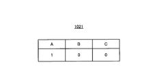
- FIG. 3 is a diagram showing an example of a battery identification table set in the control unit in the electric vehicle shown in FIG.
- the type of one or more secondary batteries mounted on the electric vehicle 100 is associated with identification information that identifies the presence or absence of one or more secondary batteries.
- three types of secondary batteries A, B, and C are associated with information indicating the presence or absence of each of the three types of secondary batteries A, B, and C.
- the secondary battery A is a nickel hydride storage battery
- the secondary battery B is a lithium ion storage battery
- the secondary battery C is a lithium ion polymer storage battery.
- “1” represents that the corresponding secondary battery is mounted in the electric vehicle 100 having the battery identification table 1021.
- “0” represents that the corresponding secondary battery is not mounted in the electric vehicle 100 having the battery identification table 1021.
- the battery identification table 1021 is stored in a storage unit (not shown) that constitutes the control unit 102. Information regarding the battery identification table 1021 included in the control unit 102 is transmitted to the control unit 202 via the communication lines 112 and 212 in S104 illustrated in FIG. 2, for example.
- the battery specification table 1021 information related to the three secondary batteries A, B, and C is recorded in the battery specification table 1021, but specific information related to storage batteries other than these secondary batteries may be recorded in the battery specification table 1021.
- the battery identification table 1021 may record identification information regarding one secondary battery instead of the identification information regarding the plurality of secondary batteries A, B, and C.
- FIG. 4 is a diagram showing an example of a charging method correspondence table set in the control unit in the charging / discharging device shown in FIG.
- the charging method correspondence table 2021 shown in FIG. 4 charging according to the type of one or more secondary batteries mounted on the electric vehicle 100 and the characteristics of the one or more secondary batteries mounted on the electric vehicle 100 is performed.
- Correspondence information “1” indicating that the system is supported is associated with non-corresponding information “0” indicating that the system is not compatible with the charging system.
- the charging method correspondence table 2021 is stored in a storage unit (not shown) constituting the control unit 202. Information related to the charging method correspondence table 2021 included in the control unit 202 is transmitted to the control unit 102 via the communication lines 112 and 212 in S104 illustrated in FIG.
- correspondence information and non-correspondence information about the three secondary batteries A, B, and C are recorded in the charging method correspondence table 2021, but the charging method correspondence table 2021 relates to storage batteries other than these secondary batteries. Corresponding information and non-corresponding information may be recorded.
- the charging method correspondence table 2021 may record correspondence information or non-correspondence information regarding one secondary battery instead of correspondence information and non-correspondence information regarding the plurality of secondary batteries A, B, and C.
- FIG. 5 is a diagram for explaining processing for determining whether or not charging is possible based on the battery identification table shown in FIG. 3 and the charging method correspondence table shown in FIG. FIG. 5 shows, as an example, information on three secondary batteries A, B, and C recorded on each of 27 types of battery specifying tables 1021 and information on the charging method correspondence table 2021.
- “ ⁇ ” Means that either the chargeable information “1” or the non-chargeable information “0” may be used.
- the information corresponding to the secondary batteries A, B, and C shown in the column 1 is connected to the information in the battery specification table 1021 of the first automobile among the plurality of electric automobiles 100 and the first automobile.
- the information corresponding to the secondary batteries A, B, and C shown in the column 2 includes information in the battery specification table 1021 included in a second vehicle different from the first vehicle among the plurality of electric vehicles 100, and This is information in the charging method correspondence table 2021 included in the charging / discharging device 200 connected to the second automobile.
- Whether or not charging is possible is determined by the logical product of the information corresponding to the same type of secondary battery in the information on the secondary battery shown in the battery identification table 1021 and the information on the secondary battery shown in the charging method correspondence table 2021. When it is “1”, it is determined as “chargeable”, and when the logical product of information corresponding to the same type of secondary battery is “0”, it is determined as “not chargeable”.
- the information of the secondary battery A in the battery identification table 1021 is “1”, and the secondary battery A in the charging method correspondence table 2021 included in the charging / discharging device 200 connected to the electric vehicle 100 having the battery identification table 1021. If the information is “1”, the charging / discharging device 200 determines that charging is possible because the charging / discharging device 200 corresponds to the charging method according to the characteristics of the power supply source 101 mounted on the electric vehicle 100.
- No. A method for determining whether or not charging is possible will be described using the information shown in the column 4 as an example.
- the information of the secondary battery B in the battery identification table 1021 is “1”, and the secondary battery B in the charging method correspondence table 2021 included in the charging / discharging device 200 connected to the electric vehicle 100 having the battery identification table 1021. Is “0”, the charging / discharging device 200 determines that charging is not possible because the charging / discharging device 200 does not support the charging method according to the characteristics of the power supply source 101 mounted on the electric vehicle 100.
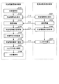
- FIG. 6 is a flowchart of chargeability determination processing in S105 shown in FIG.
- the control unit 202 determines chargeability based on the chargeability correspondence table shown in FIG. 5 in S301 of FIG.
- the control part 202 has received the charge instruction
- the control unit 202 notifies the control unit 102 of the end of charging / discharging, and charging / discharging control on the electric vehicle side. End.
- step S304 the control unit 202 notifies the user that the electric vehicle 100 connected to the charging / discharging device 200 is equipped with a power supply source 101 that cannot be charged.
- the charging / discharging device is currently connected. Is not supported for charging an electric vehicle.
- the message information is transmitted to a controller (not shown) that controls the charging / discharging device 200, and the controller that has received the message information displays the message as character information on a display screen provided in the controller. .
- control unit 202 that has completed the notification to the user ends the charge availability determination process in S305.
- control unit 202 ends the charging permission determination process in S306, and performs the processing after S106 in FIG.
- control unit 202 ends the charging permission determination process in S306, and performs the processes after S106 in FIG.
- the charging / discharging device 200 corresponds to the correspondence information indicating that the charging method corresponds to the characteristic of the power supply source 101 that is a secondary battery, and the charging method. It is configured to determine whether or not the secondary battery in the electric vehicle 100 that is an automobile connected to the charging / discharging device 200 can be charged using non-corresponding information indicating that the charging / discharging apparatus 200 is not used. As a result, charging of the power supply source 101 that does not correspond to the charging method according to the characteristics of the power supply source 101 can be prevented, and performance deterioration of the power supply source 101 or the charging / discharging device 200 can be suppressed. Further, by performing the chargeability determination process before the conductor 103 is turned on, it is possible to prevent the power stored in the power supply source 101 from being output to the outside.
- the power supply source 101 mounted on the electric vehicle 100 is a secondary battery such as a nickel metal hydride storage battery, a lithium ion storage battery, or a lithium ion polymer storage battery has been described.
- power sources such as an internal combustion engine and a fuel cell are mounted.
- charging / discharging device 200 according to the present embodiment is connected to an automobile equipped with at least one of these power sources, it is also possible to determine whether or not the power source installed in the automobile can be charged. is there.
- a specific example will be described below.
- FIG. 7 is a diagram showing an example of a power source specifying table set in a control unit of a vehicle equipped with a power source such as a secondary battery, an internal combustion engine, or a fuel cell instead of the electric vehicle shown in FIG.
- a power source such as a secondary battery, an internal combustion engine, or a fuel cell instead of the electric vehicle shown in FIG.
- the power source specification table 1021A shown in FIG. 7 is associated with the type of power source mounted on the automobile and specific information for specifying the presence or absence of the power source.
- three types of power sources are associated with information indicating the presence or absence of each of the three types of power sources.
- A1 is a secondary battery
- B1 is an internal combustion engine
- C1 is a fuel cell.
- the power source illustrated here is an example and is not limited thereto. “1” represents that the corresponding power source is mounted in the automobile having the power source specifying table 1021A. “0” represents that the corresponding power source is not mounted in the automobile having the power source specifying table 1021A.
- the power source identification table 1021 ⁇ / b> A is stored in a storage unit (not shown) that constitutes the control unit 102. Information relating to the power source identification table 1021A included in the control unit 102 is transmitted to the control unit 202 via the communication lines 112 and 212, for example, in S104 illustrated in FIG.
- FIG. 8 is a view showing a modification of the charging method correspondence table set in the control unit in the charging / discharging device shown in FIG.
- the charging method correspondence table 2021A shown in FIG. 8 includes the type of power source mounted on the vehicle, chargeable information “1” indicating that the power source mounted on the vehicle can be charged, and the power The charge disable information “0” indicating that the source cannot be charged is associated.
- the charging method correspondence table 2021A is stored in a storage unit (not shown) constituting the control unit 202. Information regarding the charging method correspondence table 2021A included in the control unit 202 is transmitted to the control unit 102 via the communication lines 112 and 212 in S104 illustrated in FIG.
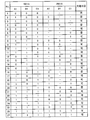
- FIG. 9 is a diagram for explaining processing for determining whether or not charging is possible based on the power source specifying table shown in FIG. 7 and the charging method correspondence table shown in FIG. In FIG. 5, as an example, three power sources A1, B1, C1 and information on the charging method correspondence table 2021A recorded in each of the 27 types of power source specifying tables 1021A are shown. “ ⁇ ” Means that either the chargeable information “1” or the non-chargeable information “0” may be used.
- Whether or not charging is possible is determined by the logical product of the information corresponding to the same type of power source among the information on the power source shown in the power source specifying table 1021A and the information on the power source shown in the charging method correspondence table 2021A being “1”. ”Is determined as“ chargeable ”, and when the logical product of the information corresponding to the same type of power source is“ 0 ”, it is determined as“ not chargeable ”. “ ⁇ ” Means that either the chargeable information “1” or the non-chargeable information “0” may be used.
- No. A method for determining whether or not charging is possible will be described using the information shown in the column 3 as an example.
- the power source A1 is a secondary battery.
- Information on the power source A1 in the power source identification table 1021A is “1”, and the information on the power source A1 in the charging method correspondence table 2021A included in the charging / discharging device 200 connected to the automobile having the power source identification table 1021A. Is “1”, the charging / discharging device 200 determines that the secondary battery mounted in the automobile can be charged.
- No. A method for determining whether or not charging is possible will be described using the information shown in the column 4 as an example.
- the power source B1 is a fuel cell.
- Information on the power source B1 in the power source identification table 1021A is “1”, and information on the power source B1 in the charging method correspondence table 2021A included in the charging / discharging device 200 connected to the automobile having the power source identification table 1021A. Is “0”, the charging / discharging device 200 determines that the fuel cell mounted in the automobile cannot be charged.
- No. A method for determining whether or not charging is possible will be described using the information shown in the column 12 as an example.
- the power source A1 is a nickel hydride secondary battery and the power source C1 is a lithium ion secondary battery.
- the information of the power sources A1 and C1 in the power source specifying table 1021A is “1”, and the power source A1 in the charging method correspondence table 2021A included in the charging / discharging device 200 connected to the automobile having the power source specifying table 1021A.
- C1 is “1”
- the charging / discharging device 200 determines that the nickel hydride secondary battery and the lithium ion secondary battery are mounted on the vehicle, and determines that the secondary battery can be charged. To do.
- the control unit 202 performs the process shown in FIGS. 2 and 6 using the tables shown in FIGS. 7 and 8, and determines whether or not charging is possible.
- a fuel cell vehicle can supply electric power generated by a chemical reaction of hydrogen to home appliances, but cannot be charged.
- the charging / discharging device 200 In a state where the charging / discharging device 200 is connected to the fuel cell vehicle, when the user erroneously performs a charging operation and a charging command is output, the charging / discharging device 200 does not support charging of the fuel cell, so charging is impossible. to decide. Thereby, the safety of the charging / discharging device 200 and the fuel cell vehicle is maintained.
- the configuration described in the above embodiment shows an example of the contents of the present invention, and can be combined with another known technique, and can be combined with other configurations without departing from the gist of the present invention. It is also possible to omit or change the part.
- 10 power system, 20 distribution board, 30 load 100 electric vehicle, 101 power supply source, 102, 202 control unit, 103 conductor, 104 inlet, 110, 113, 210 power line, 111, 211 signal line, 112, 212 communication Wire, 200 charge / discharge device, 201 power conversion unit, 203 interconnection switch, 204 charge / discharge connector, 300 charge / discharge system, 1021 battery identification table, 1021A power source identification table, 2021, 2021A charge system correspondence table.
Landscapes
- Engineering & Computer Science (AREA)
- Power Engineering (AREA)
- Transportation (AREA)
- Mechanical Engineering (AREA)
- Life Sciences & Earth Sciences (AREA)
- Sustainable Development (AREA)
- Sustainable Energy (AREA)
- Charge And Discharge Circuits For Batteries Or The Like (AREA)
- Electric Propulsion And Braking For Vehicles (AREA)
Abstract
L'invention porte sur un dispositif de charge/décharge 200 qui est pourvu : d'une unité de conversion électrique 201, qui convertit un courant alternatif en un courant continu et qui fournit le courant à une source d'alimentation électrique 101 dans un véhicule électrique 100 ; d'une unité de commande 202, qui commande l'unité de conversion électrique 201 et qui effectue une transmission d'informations entre le véhicule électrique 100 et l'unité de commande. À l'aide d'informations de correspondance indiquant que le dispositif de charge/décharge correspond bien à un système de charge correspondant aux caractéristiques de la source d'alimentation électrique 101, et d'informations de non correspondance indiquant que le dispositif de charge/décharge ne correspond pas au système de charge, l'unité de commande 202 détermine si la charge peut être effectuée relativement à la source d'alimentation électrique 101 dans le véhicule électrique 100 connecté au dispositif de charge/décharge 200.
Priority Applications (4)
| Application Number | Priority Date | Filing Date | Title |
|---|---|---|---|
| JP2018502897A JP6469307B2 (ja) | 2016-03-01 | 2016-03-01 | 充放電装置 |
| US16/068,006 US20190001834A1 (en) | 2016-03-01 | 2016-03-01 | Charge/discharge apparatus |
| PCT/JP2016/056186 WO2017149638A1 (fr) | 2016-03-01 | 2016-03-01 | Dispositif de charge/décharge |
| CN201680082455.XA CN108966678A (zh) | 2016-03-01 | 2016-03-01 | 充放电装置 |
Applications Claiming Priority (1)
| Application Number | Priority Date | Filing Date | Title |
|---|---|---|---|
| PCT/JP2016/056186 WO2017149638A1 (fr) | 2016-03-01 | 2016-03-01 | Dispositif de charge/décharge |
Publications (1)
| Publication Number | Publication Date |
|---|---|
| WO2017149638A1 true WO2017149638A1 (fr) | 2017-09-08 |
Family
ID=59743581
Family Applications (1)
| Application Number | Title | Priority Date | Filing Date |
|---|---|---|---|
| PCT/JP2016/056186 Ceased WO2017149638A1 (fr) | 2016-03-01 | 2016-03-01 | Dispositif de charge/décharge |
Country Status (4)
| Country | Link |
|---|---|
| US (1) | US20190001834A1 (fr) |
| JP (1) | JP6469307B2 (fr) |
| CN (1) | CN108966678A (fr) |
| WO (1) | WO2017149638A1 (fr) |
Cited By (2)
| Publication number | Priority date | Publication date | Assignee | Title |
|---|---|---|---|---|
| JP2019165622A (ja) * | 2018-03-19 | 2019-09-26 | ドクター エンジニール ハー ツェー エフ ポルシェ アクチエンゲゼルシャフトDr. Ing. h.c. F. Porsche Aktiengesellschaft | インテリジェント電池の直流充電 |
| JP2019183628A (ja) * | 2018-04-03 | 2019-10-24 | 文化シヤッター株式会社 | 開閉装置の電源切替装置 |
Families Citing this family (3)
| Publication number | Priority date | Publication date | Assignee | Title |
|---|---|---|---|---|
| US20230331108A1 (en) * | 2022-05-08 | 2023-10-19 | Kenneth Stephen Bailey | Miniature EV Battery Charger and Range Extender |
| DE102022210620A1 (de) * | 2022-10-07 | 2024-04-18 | Volkswagen Aktiengesellschaft | Verfahren zum Kontrollieren eines Ladevorgangs, Fahrzeug, Computerprogrammprodukt und Speichermedium |
| US11855469B1 (en) | 2023-03-10 | 2023-12-26 | Beta Air, Llc | Systems and methods for bidirectional charging |
Citations (4)
| Publication number | Priority date | Publication date | Assignee | Title |
|---|---|---|---|---|
| JP2008067418A (ja) * | 2006-09-04 | 2008-03-21 | Nippon Telegr & Teleph Corp <Ntt> | 充電制御方法、蓄電装置および充電制御システム |
| JP2009136109A (ja) * | 2007-11-30 | 2009-06-18 | Toyota Motor Corp | 充電制御装置および充電制御方法 |
| JP2013211951A (ja) * | 2012-03-30 | 2013-10-10 | Toyota Industries Corp | 電力制御装置 |
| JP2015097441A (ja) * | 2013-11-15 | 2015-05-21 | シャープ株式会社 | 充放電装置 |
Family Cites Families (7)
| Publication number | Priority date | Publication date | Assignee | Title |
|---|---|---|---|---|
| US5656917A (en) * | 1995-12-14 | 1997-08-12 | Motorola, Inc. | Battery identification apparatus and associated method |
| US8638011B2 (en) * | 2009-07-10 | 2014-01-28 | Protonex Technology Corporation | Portable power manager operating methods |
| US20120109519A1 (en) * | 2010-10-27 | 2012-05-03 | Honda Motor Co., Ltd. | System and method for routing bev to charging station |
| WO2013128635A1 (fr) * | 2012-03-02 | 2013-09-06 | 株式会社 日立製作所 | Système d'analyse de batterie d'accumulateurs, procédé d'analyse de batterie d'accumulateurs et programme d'analyse de batterie d'accumulateurs |
| KR101721517B1 (ko) * | 2013-03-26 | 2017-03-30 | 쥬코쿠 덴료쿠 가부시키 가이샤 | 충방전 시스템의 제어 방법, 및 충방전 시스템 |
| DK3031659T3 (en) * | 2014-12-12 | 2019-02-25 | Energybus E V | Modular vehicle system with increased reliability |
| US9847658B2 (en) * | 2014-12-31 | 2017-12-19 | Meridian Design, Inc. | Systems and methods for performing battery management |
-
2016
- 2016-03-01 JP JP2018502897A patent/JP6469307B2/ja not_active Expired - Fee Related
- 2016-03-01 US US16/068,006 patent/US20190001834A1/en not_active Abandoned
- 2016-03-01 WO PCT/JP2016/056186 patent/WO2017149638A1/fr not_active Ceased
- 2016-03-01 CN CN201680082455.XA patent/CN108966678A/zh not_active Withdrawn
Patent Citations (4)
| Publication number | Priority date | Publication date | Assignee | Title |
|---|---|---|---|---|
| JP2008067418A (ja) * | 2006-09-04 | 2008-03-21 | Nippon Telegr & Teleph Corp <Ntt> | 充電制御方法、蓄電装置および充電制御システム |
| JP2009136109A (ja) * | 2007-11-30 | 2009-06-18 | Toyota Motor Corp | 充電制御装置および充電制御方法 |
| JP2013211951A (ja) * | 2012-03-30 | 2013-10-10 | Toyota Industries Corp | 電力制御装置 |
| JP2015097441A (ja) * | 2013-11-15 | 2015-05-21 | シャープ株式会社 | 充放電装置 |
Cited By (4)
| Publication number | Priority date | Publication date | Assignee | Title |
|---|---|---|---|---|
| JP2019165622A (ja) * | 2018-03-19 | 2019-09-26 | ドクター エンジニール ハー ツェー エフ ポルシェ アクチエンゲゼルシャフトDr. Ing. h.c. F. Porsche Aktiengesellschaft | インテリジェント電池の直流充電 |
| US11152797B2 (en) | 2018-03-19 | 2021-10-19 | Dr. Ing. H.C. F. Porsche Aktiengesellschaft | DC charging of an intelligent battery |
| JP2019183628A (ja) * | 2018-04-03 | 2019-10-24 | 文化シヤッター株式会社 | 開閉装置の電源切替装置 |
| JP7303000B2 (ja) | 2018-04-03 | 2023-07-04 | 文化シヤッター株式会社 | 開閉装置の電源切替装置 |
Also Published As
| Publication number | Publication date |
|---|---|
| JPWO2017149638A1 (ja) | 2018-06-28 |
| JP6469307B2 (ja) | 2019-02-13 |
| CN108966678A (zh) | 2018-12-07 |
| US20190001834A1 (en) | 2019-01-03 |
Similar Documents
| Publication | Publication Date | Title |
|---|---|---|
| US11958409B2 (en) | Vehicle and method of notifying charging information of vehicle | |
| EP3517351B1 (fr) | Véhicule, chargeur, système de chargement comprenant un chargeur et procédé de diagnostic d'anomalie pour chargeur | |
| US11167657B2 (en) | Vehicle charging system | |
| JP6142729B2 (ja) | 充電システム、車両および充電設備 | |
| JP6044460B2 (ja) | 車両の電源装置 | |
| CN104283238B (zh) | 用于移动终端的车载无线充电系统 | |
| US10414285B2 (en) | Apparatus and method for preventing over-charging of battery | |
| CN104283239B (zh) | 用于移动终端的车载无线充电系统 | |
| JP7528784B2 (ja) | 電力伝送システム | |
| JP5632771B2 (ja) | 交流電流供給装置の制御器、及び交流電流供給方法 | |
| JP6469307B2 (ja) | 充放電装置 | |
| US9346366B2 (en) | Charge/discharge system | |
| CN111086402B (zh) | 车辆及车辆的控制方法 | |
| JP5811287B2 (ja) | 車両 | |
| CN113659681A (zh) | 一种从控模块、电池管理系统、方法及存储介质 | |
| US9108522B2 (en) | Vehicle-mounted controller | |
| KR101996446B1 (ko) | 전기 차량 충전용 변환 어댑터의 전원공급장치 및 이를 구비한 전기 차량 충전용 변환 어댑터 | |
| CN113364827A (zh) | 信息通知设备、信息通知系统、信息通知方法和车辆 | |
| JP6597556B2 (ja) | 電動車両 | |
| CN112154087B (zh) | 电动车辆及电动车辆控制方法 | |
| JP2011050162A (ja) | 車両 | |
| CN117879078A (zh) | 充放电状态显示装置 | |
| JP2014033512A (ja) | 電源供給システムおよびこれに用いる電源供給装置 |
Legal Events
| Date | Code | Title | Description |
|---|---|---|---|
| ENP | Entry into the national phase |
Ref document number: 2018502897 Country of ref document: JP Kind code of ref document: A |
|
| NENP | Non-entry into the national phase |
Ref country code: DE |
|
| 121 | Ep: the epo has been informed by wipo that ep was designated in this application |
Ref document number: 16892483 Country of ref document: EP Kind code of ref document: A1 |
|
| 122 | Ep: pct application non-entry in european phase |
Ref document number: 16892483 Country of ref document: EP Kind code of ref document: A1 |