WO2017149657A1 - 風車起動アシスト装置 - Google Patents
風車起動アシスト装置 Download PDFInfo
- Publication number
- WO2017149657A1 WO2017149657A1 PCT/JP2016/056258 JP2016056258W WO2017149657A1 WO 2017149657 A1 WO2017149657 A1 WO 2017149657A1 JP 2016056258 W JP2016056258 W JP 2016056258W WO 2017149657 A1 WO2017149657 A1 WO 2017149657A1
- Authority
- WO
- WIPO (PCT)
- Prior art keywords
- blade
- speed
- wind
- blade rotation
- windmill
- Prior art date
- Legal status (The legal status is an assumption and is not a legal conclusion. Google has not performed a legal analysis and makes no representation as to the accuracy of the status listed.)
- Ceased
Links
Images


Classifications
-
- F—MECHANICAL ENGINEERING; LIGHTING; HEATING; WEAPONS; BLASTING
- F03—MACHINES OR ENGINES FOR LIQUIDS; WIND, SPRING, OR WEIGHT MOTORS; PRODUCING MECHANICAL POWER OR A REACTIVE PROPULSIVE THRUST, NOT OTHERWISE PROVIDED FOR
- F03D—WIND MOTORS
- F03D7/00—Controlling wind motors
- F03D7/02—Controlling wind motors the wind motors having rotation axis substantially parallel to the air flow entering the rotor
- F03D7/026—Controlling wind motors the wind motors having rotation axis substantially parallel to the air flow entering the rotor for starting-up
-
- F—MECHANICAL ENGINEERING; LIGHTING; HEATING; WEAPONS; BLASTING
- F03—MACHINES OR ENGINES FOR LIQUIDS; WIND, SPRING, OR WEIGHT MOTORS; PRODUCING MECHANICAL POWER OR A REACTIVE PROPULSIVE THRUST, NOT OTHERWISE PROVIDED FOR
- F03D—WIND MOTORS
- F03D7/00—Controlling wind motors
- F03D7/02—Controlling wind motors the wind motors having rotation axis substantially parallel to the air flow entering the rotor
- F03D7/04—Automatic control; Regulation
- F03D7/042—Automatic control; Regulation by means of an electrical or electronic controller
- F03D7/047—Automatic control; Regulation by means of an electrical or electronic controller characterised by the controller architecture, e.g. multiple processors or data communications
-
- F—MECHANICAL ENGINEERING; LIGHTING; HEATING; WEAPONS; BLASTING
- F05—INDEXING SCHEMES RELATING TO ENGINES OR PUMPS IN VARIOUS SUBCLASSES OF CLASSES F01-F04
- F05B—INDEXING SCHEME RELATING TO WIND, SPRING, WEIGHT, INERTIA OR LIKE MOTORS, TO MACHINES OR ENGINES FOR LIQUIDS COVERED BY SUBCLASSES F03B, F03D AND F03G
- F05B2260/00—Function
- F05B2260/85—Starting
-
- F—MECHANICAL ENGINEERING; LIGHTING; HEATING; WEAPONS; BLASTING
- F05—INDEXING SCHEMES RELATING TO ENGINES OR PUMPS IN VARIOUS SUBCLASSES OF CLASSES F01-F04
- F05B—INDEXING SCHEME RELATING TO WIND, SPRING, WEIGHT, INERTIA OR LIKE MOTORS, TO MACHINES OR ENGINES FOR LIQUIDS COVERED BY SUBCLASSES F03B, F03D AND F03G
- F05B2270/00—Control
- F05B2270/10—Purpose of the control system
- F05B2270/20—Purpose of the control system to optimise the performance of a machine
-
- F—MECHANICAL ENGINEERING; LIGHTING; HEATING; WEAPONS; BLASTING
- F05—INDEXING SCHEMES RELATING TO ENGINES OR PUMPS IN VARIOUS SUBCLASSES OF CLASSES F01-F04
- F05B—INDEXING SCHEME RELATING TO WIND, SPRING, WEIGHT, INERTIA OR LIKE MOTORS, TO MACHINES OR ENGINES FOR LIQUIDS COVERED BY SUBCLASSES F03B, F03D AND F03G
- F05B2270/00—Control
- F05B2270/30—Control parameters, e.g. input parameters
- F05B2270/32—Wind speeds
-
- F—MECHANICAL ENGINEERING; LIGHTING; HEATING; WEAPONS; BLASTING
- F05—INDEXING SCHEMES RELATING TO ENGINES OR PUMPS IN VARIOUS SUBCLASSES OF CLASSES F01-F04
- F05B—INDEXING SCHEME RELATING TO WIND, SPRING, WEIGHT, INERTIA OR LIKE MOTORS, TO MACHINES OR ENGINES FOR LIQUIDS COVERED BY SUBCLASSES F03B, F03D AND F03G
- F05B2270/00—Control
- F05B2270/30—Control parameters, e.g. input parameters
- F05B2270/327—Rotor or generator speeds
-
- F—MECHANICAL ENGINEERING; LIGHTING; HEATING; WEAPONS; BLASTING
- F05—INDEXING SCHEMES RELATING TO ENGINES OR PUMPS IN VARIOUS SUBCLASSES OF CLASSES F01-F04
- F05B—INDEXING SCHEME RELATING TO WIND, SPRING, WEIGHT, INERTIA OR LIKE MOTORS, TO MACHINES OR ENGINES FOR LIQUIDS COVERED BY SUBCLASSES F03B, F03D AND F03G
- F05B2270/00—Control
- F05B2270/80—Devices generating input signals, e.g. transducers, sensors, cameras or strain gauges
- F05B2270/804—Optical devices
- F05B2270/8042—Lidar systems
-
- Y—GENERAL TAGGING OF NEW TECHNOLOGICAL DEVELOPMENTS; GENERAL TAGGING OF CROSS-SECTIONAL TECHNOLOGIES SPANNING OVER SEVERAL SECTIONS OF THE IPC; TECHNICAL SUBJECTS COVERED BY FORMER USPC CROSS-REFERENCE ART COLLECTIONS [XRACs] AND DIGESTS
- Y02—TECHNOLOGIES OR APPLICATIONS FOR MITIGATION OR ADAPTATION AGAINST CLIMATE CHANGE
- Y02E—REDUCTION OF GREENHOUSE GAS [GHG] EMISSIONS, RELATED TO ENERGY GENERATION, TRANSMISSION OR DISTRIBUTION
- Y02E10/00—Energy generation through renewable energy sources
- Y02E10/70—Wind energy
- Y02E10/72—Wind turbines with rotation axis in wind direction
Definitions
- This invention relates to a windmill start assist device for starting rotation of blades in a wind power generator.
- Patent Document 1 discloses a technology related to a startup assist control device for promoting rotation startup under a slight wind of a windmill.
- the rotational speed of a rotor is taken from a rotor sensor that detects the rotation of a rotor in a wind turbine generator, the wind turbine is in a non-rotating state, and this wind turbine stop state has elapsed for a certain period of time.
- the startup assist current supply system is turned on, and the startup assist current supply system is turned off when the windmill rotates at a certain rotational speed or more due to wind power.
- the wind speed is taken as a control element in addition to the rotation speed of the rotor, the windmill is in a non-rotating state, and the wind speed is equal to or higher than the self-starting wind speed of the windmill, The supply system is turned on.
- Patent Document 1 since the technology disclosed in Patent Document 1 starts the start assist when the windmill is in a non-rotating state, there is a problem that a large amount of power is required for the assist. Further, it is assumed that only the wind speed in the vicinity of the windmill can be measured. In particular, when the incoming wind speed is zero at the time of assist, there is a problem that the start assist fails and the power loss increases.
- the present invention has been made to solve the above-described problems, and an object thereof is to provide a windmill start assist device capable of increasing the efficiency of windmill start and improving effective power generation. .
- a windmill start assist device includes a blade rotation speed calculation unit that calculates a blade rotation speed when a blade of a windmill passes a laser beam output from a wind measurement lidar device installed on the windmill nacelle of the windmill.
- An incoming wind speed calculation unit that calculates an incoming wind speed based on a laser gaze direction wind speed obtained from a wind measurement lidar device, a blade rotational speed calculated by the blade rotational speed calculation unit, and an incoming wind speed calculated by the incoming wind speed calculation unit
- an activation assist control unit for controlling activation assist for promoting the activation of the rotation of the blades.
- the windmill start assist device of the present invention it is possible to improve the efficiency of windmill start and improve the effective generated power.
- FIG. 5A and 5B are diagrams for explaining the positional relationship between the laser emission direction and the blades of the wind measurement lidar apparatus in the blade passage determination, blade rotation speed detection, and arrival wind speed detection of the present invention.
- FIGS. 6A and 6B are diagrams showing the relationship between the rotation of the wind turbine blades and the emitted laser light of the wind measurement lidar apparatus in the first embodiment.
- the activation assist control unit starts the activation assist control based on the determination result of the blade passage determination unit, the blade rotation speed calculation unit, the incoming wind speed calculation unit, or the calculation result, and the activation assist It is a figure explaining the case where control is not started by a time series image.
- the activation assist control unit starts the activation assist control based on the determination result of the blade passage determination unit, the blade rotation speed calculation unit, the incoming wind speed calculation unit, or the calculation result, and the activation assist It is a figure explaining the case where control is not started by a time series image.
- 9A and 9B are diagrams showing an example of a hardware configuration of the windmill start assist device according to Embodiment 1 of the present invention.
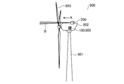
- FIG. 1 is a diagram for explaining a schematic configuration of a wind turbine generator that performs start assist control or power generation control for the wind turbine start assist device 100 according to Embodiment 1 of the present invention to start rotation of a blade 903. It is.
- the wind power generator is assumed to be of a horizontal axis type.
- the wind power generator is simply referred to as a windmill 900.
- the windmill 900 includes a wind measurement lidar device 200 on a windmill nacelle 902 on a tower 901.
- the windmill nacelle 902 includes the windmill activation assist device 100 and a generator 905, and a blade, that is, a blade 903 is rotatably fixed to the tip of the windmill nacelle 902.
- the root of the blade 903 is connected to the rotor shaft by a hub (not shown), and the wind turbine nacelle 902 and the blade 903 are connected from the hub through the rotor shaft.
- the windmill activation assist device 100 may be provided outside the windmill nacelle 902.
- the windmill start assist device 100 performs control to apply a current for start assist when it is determined that start assist is necessary, and the start assist driver 9001 (described later) starts the windmill. Based on the control of the assist device 100, an electric current is applied to assist the activation of the blade 903. Further, the windmill activation assist device 100 performs control to turn off the activation assist current when the blade 903 reaches a certain rotation speed. That is, the windmill start assist device 100 controls the start or end of the start assist for promoting the start of rotation of the blades 903.
- the windmill 900 includes a start assist driver 9001 (described later in FIG. 2).
- the start assist driver 9001 receives a windmill start signal from the windmill start assist device 100. Then, the power for starting the windmill is generated. Details of the configuration and operation of the windmill activation assist device 100 will be described later.
- the generator 905 converts the rotation of the blade 903 into electricity based on the control of the windmill start assist device 100 to generate electricity.
- the generator 905 includes a power generation control driver 9002 (described later in FIG. 2), and the power generation control driver 9002 receives a signal for switching to the power generation operation from the windmill activation assist device 100 and generates power.
- the wind measurement lidar device 200 is installed on the windmill nacelle 902 of the windmill 900.
- the wind measuring lidar apparatus 200 outputs at least two directions of lasers, that is, transmission light B in the direction A shown in FIG.
- the wind measurement lidar apparatus 200 outputs the transmission light B in two directions (5a and 5b in FIG. 2 described below).
- the lasers in the two directions are referred to as a first laser and a second laser, respectively.
- the wind measuring lidar apparatus 200 measures the components projected in the laser emission directions 5a and 5b of the incoming wind speed as the line-of-sight wind speeds Vm1 and Vm2.
- the windmill activation assist device 100 calculates the incoming wind speed Vwind and the incoming wind direction ⁇ wind, which is an angle with respect to the blade rotation axis, by numerical calculation using the plurality of gaze direction wind speeds.
- the incoming wind speed is a wind speed field in a space having a volume of several tens of meters centered on the height of the hub of the wind turbine 900 in the horizontal direction and several tens of meters in the horizontal direction at a predetermined distance in front of the wind turbine nacelle 902.
- the predetermined distance away from the windmill nacelle 902 is assumed to be, for example, several tens of meters to several hundreds of meters, but the predetermined distance varies depending on the scale of the windmill 900 and the installation environment.
- the line-of-sight wind speeds Vm1 and Vm2, the incoming wind speed Vwind, and the incoming wind direction ⁇ wind will be described later.
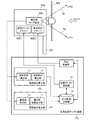
- FIG. 2 is a diagram for explaining the configuration of the windmill activation assist device 100 according to Embodiment 1 of the present invention.
- the windmill start assist device 100 includes a blade related value calculation unit 101, a wind related value calculation unit 102, a start assist control unit 14, a power generation control unit 15, and a calculation result storage unit 16.
- the blade-related value calculation unit 101 determines whether or not a blade has passed based on the measurement value of the wind measurement lidar apparatus 200, and calculates the blade rotation speed from the blade passage speed measured by the wind measurement lidar apparatus 200.
- the blade related value calculation unit 101 includes a blade passage determination unit 10 and a blade rotation speed calculation unit 11.
- the blade passage determination unit 10 determines whether the blade 903 has passed the first laser or the second laser, that is, here, the blade 903 is the first one. It is determined whether the first laser or the second laser is blocked.
- the blade rotation speed calculation unit 11 rotates when the blade 903 of the windmill 900 passes the first laser beam or the second laser beam. Calculate the speed.
- the rotational speed when the blade 903 passes the first laser light or the second laser light is referred to as an instantaneous blade rotational speed.
- the blade rotation speed calculation unit 11 calculates an average blade rotation speed calculated based on a time interval at which the blade 903 passes the first laser light or the second laser light.
- the average speed of blade rotation is referred to as average blade rotation speed.
- the blade rotation speed means that the blade 903 outputs the first laser light or the second laser light output from the wind measurement lidar device 200 installed on the windmill nacelle 902 of the windmill 900. This means the speed at the time of passing, and includes instantaneous blade rotation speed or blade rotation average speed.
- the wind related value calculation unit 102 calculates the incoming wind speed and the incoming wind direction based on the measurement values of the wind measurement lidar apparatus 200.
- the wind-related value calculation unit 102 includes an arrival wind speed calculation unit 12 and an arrival wind direction calculation unit 13.
- the incoming wind speed calculation unit 12 acquires the visual direction wind speeds of the first laser and the second laser from the wind measurement lidar apparatus 200, and calculates the incoming wind speed using the visual direction wind speeds in the plurality of directions.
- the arrival wind direction calculation unit 13 acquires the gaze direction wind speeds of the first laser and the second laser from the wind measurement lidar apparatus 200, and calculates the arrival wind direction using the gaze direction wind speeds of the plurality of directions.
- the start assist control unit 14 controls the start assist mode of the windmill based on information on the blade rotation speed and the incoming wind speed stored in the calculation result storage unit 16. Specifically, a signal for generating the power for starting the windmill is transmitted to the start assist driver 9001 included in the windmill 900.
- the power generation control unit 15 controls the power generation operation mode of the wind turbine generator 905 based on the information on the start assist off output from the start assist control unit 14. Specifically, a signal for switching the power generation operation is transmitted to the power generation control driver 9002 included in the windmill 900.
- the calculation result storage unit 16 stores the blade rotation speed calculated by the blade related value calculation unit 101 and the values of the incoming wind speed and the incoming wind direction calculated by the wind related value calculation unit 102.
- the calculation result storage unit 16 is provided in the windmill activation assist device 100.
- the calculation result storage unit 16 is not limited to this, and the windmill activation assist device 16 is not limited thereto. It may be provided outside the apparatus 100.
- FIG. 3 is a flowchart for explaining the operation of the windmill start assist device 100 according to Embodiment 1 of the present invention.
- a blade rotation speed and incoming wind speed detection process is executed (step ST301).
- the windmill start assist device 100 calculates the instantaneous blade rotation speeds ⁇ a and ⁇ b, the incoming wind speed Vwind, and the incoming wind direction ⁇ wind based on the measurement values of the wind measurement lidar apparatus 200.
- the average speed of blade rotation in the first laser light and the average speed of blade rotation in the second laser light are calculated.
- the average speed of blade rotation in the first laser light is referred to as blade average rotation speed ⁇ avea
- the average speed of blade rotation in the second laser light is referred to as blade rotation average speed ⁇ aveb.
- the blade rotation average speed ⁇ avea is determined by the i-th blade 903 from the time when the i ⁇ 1th blade 903 passes the first laser.
- the average rotation speed in the time until passing through is represented.
- the instantaneous blade rotation speed ⁇ a when the blade 903 passes the first laser light is instantaneous instantaneous blade rotation speed ⁇ a
- the blade rotation speed is ⁇ b.
- the activation assist controller 14 determines whether or not the latest instantaneous blade rotation speed ⁇ a calculated when the blade 903 passes through the first laser is greater than or equal to a predetermined reference value Ncri, calculated in the process of step ST301. Determination is made (step ST302). That is, in this step ST302, it is determined whether or not the current rotational speed of the wing 903 is sufficient.
- the activation assist control unit 14 obtains the latest instantaneous blade rotation speed ⁇ a from the calculation result storage unit 16, and which of the instantaneous blade rotation speeds ⁇ a stored in the calculation result storage unit 16 is the latest.
- the instantaneous blade rotational speed ⁇ a may be determined from the time stored in association with the instantaneous blade rotational speed ⁇ a.
- step ST302 when the instantaneous blade rotation speed ⁇ a is smaller than a predetermined reference value Ncri (in the case of “NO” in step ST302), the activation assist control unit 14 determines that the rotation speed of the blade 903 is insufficient. Judge, and return to step ST301.
- step ST302 when the instantaneous blade rotation speed ⁇ a when passing through the first laser is equal to or higher than a predetermined reference value Ncri (in the case of “YES” in step ST302), the activation assist control unit 14 It is determined whether or not rotation average speed ⁇ avea is equal to or higher than a predetermined reference value Ncri (step ST303).
- the instantaneous blade rotational speed ⁇ a and the reference value Ncri are determined.
- step ST303 the blade rotational average speed ⁇ avea and the reference value Ncri are determined. The reason for performing the determination twice with the rotational speed ⁇ a and the blade rotation average speed ⁇ avea is to avoid erroneous determination.
- the determination of the blade rotation average speed ⁇ avea and the reference value Ncri is also performed to prevent erroneous determination.
- step ST303 when the blade rotation average speed ⁇ avea is smaller than the predetermined reference value Ncri (in the case of “NO” in step ST303), the activation assist control unit 14 determines that the rotation speed of the blade 903 is insufficient. Judge, and return to step ST301.
- step ST303 when the blade rotation average speed ⁇ avea is equal to or higher than a predetermined reference value Ncri (in the case of “YES” in step ST303), the activation assist control unit 14 determines that the blade 903 is sufficiently rotated. Judge and proceed to step ST304. The activation assist controller 14 determines whether or not the measured value of the incoming wind speed Vwind calculated in the process of step ST301 is greater than zero (step ST304).
- step ST304 when the measured value of the incoming wind speed Vwind is zero (in the case of “NO” in step ST304), the activation assist control unit 14 determines that the incoming wind speed is zero and returns to step ST301.
- step ST304 when the measured value of the incoming wind speed Vwind is greater than zero (in the case of “YES” in step ST304), the activation assist control unit 14 determines the instantaneous blade rotation speed ⁇ a when passing through the first laser, and It is determined that the blade rotation average speed ⁇ avea is equal to or higher than the reference value and the incoming wind speed is greater than zero, and the transition to the activation assist mode is performed, and control in the activation assist mode is performed (step ST305).
- the start assist control unit 14 transmits a signal for generating the power for starting the windmill to the start assist driver 9001 included in the windmill 900, and the start assist for promoting the start of rotation of the blades 903 of the windmill 900. To start. Thereby, the rotation start of the wing
- Activation assist control unit 14 determines whether blade rotation average speed ⁇ avea has reached reference value N1 for shifting to the power generation mode (step ST306). Specifically, the activation assist control unit 14 determines whether or not the blade rotation average speed ⁇ avea is equal to or higher than a reference value N1 for shifting to the power generation mode. In step ST306, when blade rotation average speed ⁇ avea has not reached reference value N1 for shifting to the power generation mode (in the case of “NO” in step ST306), the process returns to step ST301.
- step ST306 when the blade rotation average speed ⁇ avea has reached the reference value N1 for shifting to the power generation mode (in the case of “YES” in step ST306), the activation assist control unit 14 ends the activation assist mode. (Step ST307). Specifically, the start assist control unit 14 stops transmission of a signal for generating power for starting the windmill to the start assist driver 9001 included in the windmill 900.
- the power generation control unit 15 detects that the start assist control unit 14 has ended the start assist in step ST307, and refers to the calculation result storage unit 16 so that the blade rotation average speed ⁇ avea is a reference value for starting power generation. It is determined whether or not N2 has been reached (step ST308). Specifically, it is determined whether the power generation control unit 15 and the blade rotation average speed ⁇ avea are equal to or higher than a reference value N2 for starting power generation. That is, in step ST308, the power generation control unit 15 shifts to a power generation operation mode in which the power generation of the wind turbine generator 905 is controlled.
- the boot assist control unit 14 turns on the boot assist mode flag that is held internally at the start of the boot assist, At the end of the start assist, the start assist mode flag is turned off, and the power generation control unit 15 may detect the start and end of the start assist by turning the start assist mode flag on and off. This is merely an example, and it is sufficient that the power generation control unit 15 can detect the start and end of the start assist by the start assist control unit 14.
- step ST308 when blade rotation average speed ⁇ avea has not reached reference value N2 for starting power generation (in the case of “NO” in step ST308), power generation control unit 15 ends power generation control (step ST309). ), The process returns to step ST301. Specifically, the power generation control unit 15 transmits a signal for stopping the power generation operation to the power generation control driver 9002 included in the windmill 900.
- step ST301 when blade rotation average speed ⁇ avea has reached reference value N2 for starting power generation (in the case of “YES” in step ST308), power generation control unit 15 starts power generation control (step ST310). ). Specifically, the power generation control unit 15 transmits a signal for switching to the power generation operation to the power generation control driver 9002 included in the windmill 900. As a result, the windmill 900 is rotated by the incoming wind speed without activation assistance.
- step ST310 when the power generation control is turned on, the process of step ST301 is performed again. When the blade rotation average speed ⁇ avea and the like are calculated, the process returns to step ST308, and the blade rotation average speed ⁇ avea is monitored. Then, the subsequent processing is repeated.
- FIG. 4 is a flowchart for explaining in detail the blade rotation speed / arrival wind speed detection process in step ST301 of FIG.
- the wind measurement lidar apparatus 200 installed on the windmill nacelle 902 has two laser emission directions 5a and 5b, and is a component projected in each laser emission direction 5a and 5b of the incoming wind speed Vwind. Are measured as line-of-sight direction wind speeds Vm1 and Vm2 (not shown), respectively.
- the first laser emission direction 5a and the second laser emission direction 5b are parallel to the ground surface, and the blade 903 rotates counterclockwise toward the windmill 900. Suppose.
- the blade 903 passes through the second laser emission direction 5b. 5B, the blade 903 is located between the second laser emission direction 5b and the first laser emission direction 5a. Further, at the blade position in FIG. 5B (c), the blade 903 passes through the first laser emission direction 5a. 5B shows a state where the blade 903 is not positioned between the first laser emission direction 5a, the second laser emission direction 5b, and between them.
- FIG. 5A in the arrangement relationship between the blade 903 and the laser emission directions 5a and 5b of the wind measuring lidar apparatus 200 and the blade rotation direction, (a), (b), (c), (d ) State is repeated.
- the blade passage determination unit 10 acquires a blade passage range signal based on the second laser light from the wind measurement lidar apparatus 200 installed on the windmill nacelle 902 of the windmill 900 (step ST401).
- the blade passing range is a fixed value determined by the distance between the wind measuring lidar device 200 and the rotating surface of the blade 903, and the fixed numerical value is used when the wind measuring lidar device 200 is installed in the wind measuring lidar device 200. Is predetermined.
- the blade passage determination unit 10 determines the magnitude relationship between the signal-to-noise ratio S0_2 and the preset threshold value SNR0 in the blade-passing range signal acquired in step ST401, and determines whether the signal-to-noise ratio S0_2 is greater than or equal to the threshold value SNR0. (Step ST402). In step ST402, when the signal-to-noise ratio S0_2 is equal to or greater than the threshold value SNR0 (in the case of “YES” in step ST402), the blade passage determination unit 10 determines that the blade has passed, and the second laser beam passes through the blade.
- the speed Vhub_5b is acquired from the wind measurement lidar apparatus 200 (step ST403).
- the passing speed when the blade 903 passes the second laser light is referred to as a blade passing speed Vhub_5b of the second laser light.
- the passage speed when the blade 903 passes the first laser light is defined as a blade passage speed Vhub_5a of the first laser light.
- the blade passing speed Vhub_5a of the first laser light will be described later.
- the blade passage determination unit 10 acquires a blade passage range signal from the wind measurement lidar apparatus 200, and can determine the presence or absence of blade passage based on the acquired blade passage range signal.
- step ST402 when the signal-to-noise ratio S0_2 is less than the threshold value SNR0 (in the case of “NO” in step ST402), the process proceeds to step ST408.
- the process after step ST408 will be described later.
- the blade rotation speed calculation unit 11 acquires the pitch angle ⁇ of the blade 903 from the control device (not shown) of the wind turbine 900, and the acquired pitch angle ⁇ of the blade 903 and the second laser light acquired in step ST403. From the line-of-sight direction Doppler velocity Vhub_LOS_5b that can be calculated from the blade passing velocity Vhub_5b, the instantaneous blade rotation speed ⁇ b [rpm] when the blade 903 passes the second laser beam is calculated using the following equation (1). (Step ST404).
- the rotational speed when the blade 903 passes the first laser light or the second laser light is referred to as an instantaneous blade rotational speed.
- the blade rotation speed calculation unit 11 calculates the instantaneous blade rotation speed ⁇ b.
- the control device of the windmill 900 is provided in the hub, and for the pitch drive device (not shown), the pitch control that changes the pitch angle ⁇ according to the wind speed, or the yaw drive device (not shown), Yaw control is performed to rotate the blades 903, the hub, and the windmill nacelle 902 in accordance with the wind direction. Further, information on the blade radius R and the angle ⁇ formed by the laser emission direction with respect to the blade rotation axis is stored in the wind measurement lidar device 200, for example, and may be acquired from the wind measurement lidar device 200. .
- the angle formed with respect to the blade rotation axis in the laser emission direction 5a is defined as + ⁇
- the angle formed with respect to the blade rotation axis in the laser emission direction 5b is defined as ⁇ .
- R blade radius ⁇ : blade pitch angle
- ⁇ angle formed by laser emission direction with respect to blade rotation axis
- FIG. 6A and 6B are diagrams showing the relationship between the blade rotation of the wind turbine 900 and the laser beam emitted from the wind measurement lidar device 200.
- FIG. 6A shows the reflection of the blade 903 in the laser emission direction 5a of the wind measurement lidar device 200.
- FIG. 6B shows the reflection of the blade 903 in the laser emission direction 5b of the wind measuring lidar apparatus 200.
- the blade passage speed Vhub at the laser irradiation position is expressed by the following equation (2).
- the line-of-sight direction Doppler velocities Vhub_Los_5a and Vhub_Los_5b with respect to the laser emission directions 5a and 5b are expressed by the following equations (3) and (4), respectively. Accordingly, from the measured value of the line-of-sight direction Doppler velocity Vhub_Los_5b at the closest distance with respect to the laser emission direction 5b, the instantaneous blade rotation speed ⁇ b [rpm] when the blade 903 passes the second laser light according to the above equation (1). Can be calculated.
- the instantaneous blade rotation speed ⁇ a [when the blade 903 passes the first laser light by the following equation (5): rpm] can be calculated.
- the blade rotation speed calculation unit 11 acquires the pitch angle ⁇ of the blade 903 from the control device (not shown) of the wind turbine 900, and the acquired pitch angle ⁇ of the blade 903 and step ST403.
- the instantaneous blade rotation speed ⁇ b [rpm] when the blade 903 passes the second laser light is calculated from the line-of-sight direction Doppler velocity Vhub_LOS_5b that can be calculated from the blade passage velocity Vhub_5b of the second laser light acquired in step S2.
- the blade rotation speed calculation unit 11 stores the instantaneous blade rotation speed ⁇ b [rpm] when the blade 903 calculated in step ST404 passes through the second laser light in association with the time information and stores it in the calculation result storage unit 16. (Step ST405). For example, assuming that the time when the blade 903 passes the second laser beam for the j-th time is represented by t (j), the blade rotational speed calculation unit 11 calculates the instantaneous blade rotational speed ⁇ b (t ( j)) [rpm] is stored in the calculation result storage unit 16.
- the blade rotation speed calculation unit 11 refers to the calculation result storage unit 16 to determine whether there is information on the past instantaneous blade rotation speed ⁇ b, that is, from the time associated with the instantaneous blade rotation speed ⁇ b calculated in step ST404. It is searched whether there is stored information of the instantaneous blade rotational speed ⁇ b at the previous time (step ST406).
- the instantaneous blade rotation speed ⁇ b calculated in step ST404 and stored in the calculation result storage unit 16 in step ST405 is the j-th instantaneous blade rotation speed at time t (j) when the blade 903 has passed the second laser beam. If it is ⁇ b, the blade rotation speed calculation unit 11 searches whether or not the information on the instantaneous blade rotation speed ⁇ b before time t (j ⁇ 1) is stored in the calculation result storage unit 16.
- step ST406 when there is no information on the past instantaneous blade rotation speed ⁇ b (in the case of “NO” in step ST406), the process returns to step ST401.
- step ST406 when there is information on the past instantaneous blade rotation speed ⁇ b (in the case of “YES” in step ST406), the blade rotation speed calculation unit 11 updates the latest instantaneous blade rotation speed ⁇ b calculated in step ST404.
- the average speed of blade rotation in the second laser light at the time pointed to is calculated using the following equation (6) (step ST407).
- the wind measuring lidar apparatus 200 is shielded by the laser beam passing through the blade 903 in the two laser emission directions 5a and 5b, and is compared with the rotating blade 903 in the closest range when measuring the wind speed.
- a scattered light echo having a high signal intensity is received.
- the presence or absence of wing passage can be determined.
- an n-blade wind turbine rotates at a constant instantaneous blade rotation speed ⁇ [rpm]
- shielding of laser light is observed at a period T in one laser emission direction 5a or 5b.
- T and ⁇ is expressed by the above equation (6).
- the optical path shielding time in the laser emission direction can be monitored, and the average speed of blade rotation can be calculated from the period. That is, the average speed of blade rotation is calculated based on the time interval at which the blade 903 passes the laser beam.
- the blade rotation speed calculation unit 11 calculates the average rotation speed of the blade 903 using the above equation (6).
- the blade rotation average speeds ⁇ avea and ⁇ aveb are the blade rotation average speeds when the blades 903 pass the first laser light or the second laser light, respectively. Based on the above equation (6), the blade rotation average speeds ⁇ avea and ⁇ aveb are calculated.
- the blade rotation speed calculation unit 11 calculates a blade rotation average speed ⁇ aveb that is an average speed of blade rotation at the time of passing the second laser beam.
- the period T in which the shielding of the laser beam is observed is, for example, from the time when the (n ⁇ 1) th blade 903 has passed the second laser beam, and the nth blade 903 has passed the second laser beam. It is possible to calculate and calculate the time difference until the time.
- the blade rotation speed calculation unit 11 stores the blade rotation average speed ⁇ aveb in the calculation result storage unit 16 in association with information on the time when the instantaneous blade rotation speed ⁇ b was calculated in step ST404.
- the blade rotation speed calculation unit 11 updates the blade rotation average speed ⁇ aveb to the latest state. Then, it progresses to step ST419.
- step ST402 if the signal-to-noise ratio S0_2 is not greater than or equal to the threshold value SNR0 in step ST402 (in the case of “NO” in step ST402), the process proceeds to step ST408.
- steps ST408 to ST414 the instantaneous blade rotation speed and average blade rotation speed calculated for the second laser emission direction 5b in steps ST401 to ST407 are calculated for the first laser emission direction 5a. Is what you do.
- the blade passage determination unit 10 acquires a blade passage range signal based on the first laser beam from the wind measurement lidar apparatus 200 installed on the windmill nacelle 902 of the windmill 900 (step ST408).
- the blade passage determination unit 10 determines the magnitude relationship between the signal-to-noise ratio S0_1 and the preset threshold value SNR0 in the blade-passing range signal acquired in step ST408, and determines whether the signal-to-noise ratio S0_1 is greater than or equal to the threshold value SNR0. (Step ST409).
- step ST409 when the signal-to-noise ratio S0_1 is greater than or equal to the threshold value SNR0 (in the case of “YES” in step ST409), the blade passage determination unit 10 determines that the blade has passed, and the first laser beam passes through the blade.
- the speed Vhub_5a is acquired from the wind measurement lidar apparatus 200 (step ST410).
- the blade rotation speed calculation unit 11 acquires the pitch angle ⁇ of the blade 903 from the control device of the windmill 900, the blade pitch ⁇ of the blade 903 acquired, and the blade passing speed of the first laser light acquired in step ST410. From the line-of-sight Doppler velocity Vhub_LOS_5a that can be calculated from Vhub_5a, the instantaneous blade rotation speed ⁇ a [rpm] when the blade 903 passes the first laser beam is calculated using the above-described equation (5) (step ST411). .
- the blade rotation speed calculation unit 11 stores the instantaneous blade rotation speed ⁇ a [rpm] when the blade 903 calculated in step ST411 passes the first laser light in association with the time information and stores it in the calculation result storage unit 16. (Step ST412). For example, assuming that the time when the blade 903 has passed the first laser beam i-th after starting measurement with the first laser beam is represented by t (i), the blade rotation speed calculation unit 11 performs the step The instantaneous blade rotation speed ⁇ a (t (i)) [rpm] calculated in ST411 is stored in the calculation result storage unit 16.
- the blade rotation speed calculation unit 11 refers to the calculation result storage unit 16 to determine whether there is information on the past instantaneous blade rotation speed ⁇ a, that is, from the time associated with the instantaneous blade rotation speed ⁇ a calculated in step ST411. It is searched whether there is stored information of the instantaneous blade rotational speed ⁇ a at the previous time (step ST413).
- the instantaneous blade rotation speed ⁇ a calculated in step ST411 and stored in the calculation result storage unit 16 in step ST412 is the instantaneous blade rotation speed ⁇ a at time t (i) when the blade 903 has passed the first laser beam.
- the blade rotation speed calculation unit 11 searches whether or not information on the instantaneous blade rotation speed ⁇ a before time t (i ⁇ 1) is stored in the calculation result storage unit 16.
- step ST413 when there is no information on the past instantaneous blade rotational speed ⁇ a (in the case of “NO” in step ST413), the process returns to step ST408.
- step ST413 when there is information on the past instantaneous blade rotation speed ⁇ a (in the case of “YES” in step ST413), the blade rotation speed calculation unit 11 calculates the latest, that is, the instantaneous blade rotation speed ⁇ a in step ST411.
- the average of the instantaneous blade rotation speed ⁇ a at the time is calculated using the above-described equation (6) (step ST414).
- the blade rotation speed calculation unit 11 associates the average of the instantaneous blade rotation speed ⁇ a, that is, the blade rotation average speed ⁇ avea with the time information when the instantaneous blade rotation speed ⁇ a is calculated in step ST411, and the calculation result Store in the storage unit 16.
- the blade rotation speed calculation unit 11 updates the blade rotation average speed ⁇ avea to the latest state. Then, it progresses to step ST419.
- step ST409 the process proceeds to step ST415.
- steps ST415 to ST4108 the line-of-sight wind speeds in the laser emission directions 5a and 5b are acquired from the wind measurement lidar apparatus 200, and the wind-related value calculation unit 102 calculates the incoming wind speed and the incoming wind direction.
- the arrival wind speed calculation part 12 of the wind related value calculation part 102 acquires the gaze direction wind speed Vm1 in the 1st laser emission direction 5a from the wind measurement lidar apparatus 200 (step ST415).
- the incoming wind speed calculation unit 12 acquires the line-of-sight direction wind speed Vm2 in the second laser emission direction 5b from the wind measurement lidar apparatus 200 (step ST416).
- the incoming wind speed calculation unit 12 uses the following formulas for the measurement values of the line-of-sight wind speed Vm1 in the first laser emission direction 5a acquired in step ST415 and the line-of-sight wind speed Vm2 in the second laser emission direction 5b acquired in step ST416.
- the incoming wind speed Vwind is calculated (step ST417).
- the incoming wind speed calculation unit 12 stores the calculated incoming wind speed Vwind in the calculation result storage unit 16 in association with the time when the incoming wind speed Vwind is calculated.
- the incoming wind speed calculation unit 12 calculates the incoming wind speed Vwind using the equation (7).
- the calculation unit 12 may acquire the incoming wind speed from the wind measurement lidar apparatus 200 and set the acquired incoming wind speed as the incoming wind speed Vwind.
- the arrival wind direction calculation unit 13 of the wind related value calculation unit 102 acquires the line-of-sight direction wind speed Vm1 in the first laser emission direction 5a acquired by the arrival wind speed calculation unit 12 in step ST415, and the arrival wind speed calculation unit 12 acquires in step ST416.
- the measurement value of the line-of-sight direction wind velocity Vm2 in the second laser emission direction 5b is acquired, and the incoming wind direction ⁇ wind is calculated by entering the following equation (8) (step ST418).
- the arrival wind direction calculation unit 13 stores the calculated arrival wind direction ⁇ wind in the calculation result storage unit 16 in association with the time when the arrival wind direction ⁇ wind is calculated.
- step ST419 the control unit (not shown) checks whether or not all the data on the instantaneous blade rotational speeds ⁇ a and ⁇ b, the blade rotational average speeds ⁇ avea and ⁇ aveb, the incoming wind speed Vwind, and the incoming wind direction ⁇ wind are stored.
- step ST419 when all the data is stored (in the case of “YES” in step ST419), the processing in FIG. 4 is terminated and the processing returns to FIG.
- step ST419 when all the data is not stored (in the case of “NO” in step ST419), the process returns to step ST401.
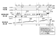
- the activation assist control unit 14 is activated based on the determination results or calculation results of the blade passage determination unit 10, the blade rotation speed calculation unit 11, and the incoming wind speed calculation unit 12. It is a figure explaining the case where control of assistance is started, and the case where control of starting assistance is not started by a time series image. 7 and 8, for convenience, the time t at which the blade 903 passes the first laser is t2, t4, t6, and the time t at which the blade 903 passes the second laser in order from the oldest time. An example is shown in which t1, t3, and t5 are set in order from time, and it is determined whether or not the start assist control is started at time t6.
- time series images of the incoming wind speed Vwind are shown in the lower part.
- the blade passes through the second laser emission direction 5b
- the blade passes through the first laser emission direction 5a.
- 7 and 8 show both information such as blade rotation speed in the first laser beam and information such as blade rotation speed in the second laser beam, but here, in FIG.
- the blade rotation speed 316 that is, the instantaneous blade rotation speed ⁇ a and the blade rotation average speed ⁇ avea exceed the blade rotation speed Ncri310 that serves as a reference for starting the start-up assistance of the windmill 900, and the incoming wind speed 324 is Since it is non-zero, start assistance of the windmill 900 is started.
- the blade rotation speed 316 that is, the instantaneous blade rotation speed ⁇ a and the blade rotation average speed ⁇ avea exceed the blade rotation speed Ncri310, which is a reference for starting the start-up assist of the windmill 900, but the incoming wind speed Vwind424 is zero. Therefore, windmill assist is not started.
- FIG. 9A and 9B are diagrams showing an example of a hardware configuration of the windmill start assist device 100 according to Embodiment 1 of the present invention.
- the blade passage determination unit 10 the blade rotation speed calculation unit 11, the incoming wind speed calculation unit 12, the incoming wind direction calculation unit 13, the activation assist control unit 14, and the power generation control unit 15
- the processing circuit 91 Each function is realized by the processing circuit 91. That is, the windmill activation assist device 100 includes a processing circuit 91 for performing activation assist control or power generation control based on the measurement value acquired from the wind measurement lidar device 200.
- the processing circuit 91 may be dedicated hardware as shown in FIG. 9A or a CPU 93 that executes a program stored in the memory 92 as shown in FIG. 9B.
- the processing circuit 91 When the processing circuit 91 is dedicated hardware, the processing circuit corresponds to, for example, a single circuit, a composite circuit, a programmed processor, a parallel programmed processor, an ASIC, an FPGA, or a combination thereof.
- the function is realized by software, firmware, or a combination of software and firmware. That is, the blade passage determination unit 10, the blade rotation speed calculation unit 11, the incoming wind speed calculation unit 12, the incoming wind direction calculation unit 13, the activation assist control unit 14, and the power generation control unit 15 are stored in the HDD 94, the memory 92, and the like. It is realized by a CPU 93 that executes a stored program, a processing circuit such as a system LSI.
- the programs stored in the HDD 94, the memory 92, and the like include a blade passage determination unit 10, a blade rotation speed calculation unit 11, an incoming wind speed calculation unit 12, an incoming wind direction calculation unit 13, and an activation assist control unit 14. It can also be said that the computer executes the procedure and method of the power generation control unit 15.
- the memory 92 is, for example, a nonvolatile or volatile semiconductor memory such as a RAM, a ROM, a flash memory, an EPROM, an EEPROM, a magnetic disk, a flexible disk, an optical disk, a compact disk, a mini disk, a DVD, or the like. Applicable.
- a part of the functions of the blade passage determination unit 10, the blade rotation speed calculation unit 11, the incoming wind speed calculation unit 12, the incoming wind direction calculation unit 13, the activation assist control unit 14, and the power generation control unit 15 are partially described. It may be realized by dedicated hardware and partly realized by software or firmware.
- the function of the blade passage determination unit 10 is realized by a processing circuit 91 as dedicated hardware, and the blade rotation speed calculation unit 11, the incoming wind speed calculation unit 12, the incoming wind direction calculation unit 13, and the startup assist control
- the functions of the unit 14 and the power generation control unit 15 can be realized by the processing circuit reading and executing the program stored in the memory 92.
- the calculation result storage unit 16 uses the HDD 94. This is merely an example, and the calculation result storage unit 16 may be configured by a DVD, a memory 92, or the like.
- the blade rotation speed is calculated in two types, the instantaneous blade rotation speed ⁇ a, ⁇ b calculated from the Doppler speed at the time of blade passage, and the blade rotation average speed ⁇ avea, ⁇ aveb calculated from the blade passage time interval at the time of blade passage, In addition, compared with the reference value, it is determined whether the blade 903 is sufficiently rotated, which contributes to higher accuracy. Moreover, the blade rotation detection sensor of the windmill 900 is unnecessary, and it can be installed in an existing windmill that does not have the rotation detection sensor.
- step ST302 of FIG. 3 the activation assist control unit 14 calculates the latest instantaneous blade rotation speed ⁇ a when the blade 903 passes the first laser, which is calculated in the process of step ST301.
- the activation assist control unit 14 is not limited to this, and the activation assist control unit 14 performs step ST301 during the steady rotation in which the blade rotation approaches the steady state. It may be determined whether or not the latest instantaneous blade rotation speed ⁇ b calculated when the blade 903 passes through the second laser is equal to or higher than a predetermined reference value Ncri. This is because the instantaneous blade rotation speed ⁇ a and the instantaneous blade rotation speed ⁇ b can be said to be equivalent during steady rotation.
- the angle difference between the emission direction of the first laser beam and the emission direction of the second laser beam is assumed to be 10 degrees to 60 degrees. This is because the distance between the measurement lidar device 200 and the blade rotation surface is assumed to be approximately the same. Note that the distance between the wind measuring lidar apparatus 200 and the blade rotation surface is about 1 m.
- the rotation tendency is determined by the sign of the calculation result of (latest instantaneous blade rotation speed ⁇ a ⁇ latest instantaneous blade rotation speed ⁇ b). Can be estimated, and the rotation tendency can also be used as an index for determining the necessity of assistance.
- the windmill start assist device 100 calculates each of the instantaneous blade rotation speed ⁇ a and the instantaneous blade rotation speed ⁇ b and stores them in the calculation result storage unit 16 as described in FIG. To leave.
- step ST302 of FIG. 3 the activation assist control unit 14 determines in advance the latest instantaneous blade rotation speed ⁇ b when the blade 903 passes through the second laser, which is calculated in the process of step ST301.
- step ST303 whether the blade rotation average speed ⁇ aveb when the blade 903 passes through the second laser is greater than or equal to a predetermined reference value Ncri. Judgment is made.
- both the instantaneous blade rotational speed ⁇ a and the blade rotational average speed ⁇ avea are determined to be the reference value Ncri.
- the present invention is not limited to this, and the instantaneous blade rotational speed ⁇ a and the reference value Ncri are determined. May not be performed, or the blade rotation average speed ⁇ avea and the reference value Ncri may not be determined.
- the wind measurement lidar apparatus 200 outputs transmission light in two directions, but is not limited thereto, and may output transmission light only in one direction, or more than three directions. It is also possible to output transmission light.
- the wind measuring lidar apparatus 200 outputs laser light in three or more directions, it is possible to detect the wind speed components in the vertical direction, that is, ascending and descending.
- the wind measurement lidar apparatus 200 is installed outside the windmill 900.
- the installation of the wind measuring lidar apparatus 200 has an effect that it is possible to measure the incoming wind from a long distance with high accuracy.
- the wind measuring lidar apparatus 200 has a function of separating and measuring the wind speed component parallel to the laser beam emission direction, that is, the line-of-sight direction, for each distance.
- the height of the hub of the windmill 900 is several tens of meters, and an anemometer installed on the ground needs to estimate the wind speed at the height of the hub from the wind speed on the ground, and a reduction in accuracy is inevitable. If the anemometer is installed on a mast with a height of several tens of meters, it is not impossible to measure the wind speed at the height of the hub, but it costs money to install the mast. Problem arises.
- the windmill nacelle 902 is rotated in the azimuth direction so as to face the incoming wind direction.
- a plurality of wind speeds around the windmill 900 is obtained.
- the installation cost of the anemometer is required, and there is an unavoidable reduction in power generation efficiency due to shielding of the incoming wind by a plurality of masts.
- the wind measuring lidar device 200 since the wind measuring lidar device 200 is installed in the windmill nacelle 902 here, the wind measuring lidar device 200 can measure the wind speed arriving at the windmill 900 with high accuracy. There is an effect that it can be monitored in real time for each arrival distance.
- the windmill start assist device 100 is configured as shown in FIG. 2, but the windmill start assist device 100 includes the blade rotation speed calculation unit 11, the incoming wind speed calculation unit 12, and the start assist.
- the control unit 14 By providing the control unit 14, the above-described effects can be obtained.
- the present invention can be modified with any component of the embodiment or omitted with any component of the embodiment.
- the windmill start assist device is configured to increase the efficiency of windmill start at a low wind speed and to improve the effective generated power, the wind power generator is started at a low wind speed. It can be applied to a windmill start assist device or the like.
Landscapes
- Engineering & Computer Science (AREA)
- Life Sciences & Earth Sciences (AREA)
- Sustainable Development (AREA)
- Sustainable Energy (AREA)
- Chemical & Material Sciences (AREA)
- Combustion & Propulsion (AREA)
- Mechanical Engineering (AREA)
- General Engineering & Computer Science (AREA)
- Wind Motors (AREA)
Abstract
Description
そこで、例えば、特許文献1には、風車の微風下における回転起動を促進するための起動アシスト制御装置に関する技術が開示されている。
特許文献1では、風車の発電機における回転子の回転を検出する回転子センサから回転子の回転数を取り込み、風車が非回転状態にあり、かつ、この風車停止の状態が一定時間経過しても風車停止が継続している場合には、起動アシスト用電流供給系統をオンとし、風車が風力により一定回転数以上で回転した時に起動アシスト用電流供給系統をオフとするようにしている。また、特許文献1では、回転子の回転数に加えて、風速を制御要素として取り込み、風車が非回転状態にあり、かつ、風速が風車の自己起動風速以上である場合に、起動アシスト用電流供給系統をオンとするようにしている。
実施の形態1.
図1は、この発明の実施の形態1に係る風車起動アシスト装置100が翼903の回転を起動させるための起動アシストの制御、あるいは、発電の制御を行う風力発電装置の概略構成を説明する図である。
なお、ここでは、風力発電装置は、水平軸型のものを想定している。以下、ここでは、風力発電装置は、単に風車900というものとする。
図1に示すように、風車900は、タワー901上の、風車ナセル902上に、風計測ライダ装置200を備える。
そして、風車900に風が到来することにより、翼903が回転して発電が行われる。
なお、風車起動アシスト装置100は、風車ナセル902の外部に備えられるものであってもよい。
風車900は、起動アシストドライバ9001(図2で後述する)を備え、風車起動アシスト装置100により起動アシストが開始されると、起動アシストドライバ9001が、風車起動アシスト装置100から風車起動の信号を受信し、風車起動の動力を発生させる。風車起動アシスト装置100の構成および動作の詳細については後述する。
風計測ライダ装置200は、図1に示すA方向に、少なくとも2方向のレーザ、すなわち、送信光Bを出力する。ここでは、風計測ライダ装置200は、2方向(以下説明する図2の5a,5b)に、送信光Bを出力するものとする。当該2方向のレーザを、それぞれ、第1のレーザ、第2のレーザとする。
風計測ライダ装置200は、到来風速の各レーザの出射方向5a,5bで射影した成分を視線方向風速Vm1,Vm2として計測する。風車起動アシスト装置100では、当該複数方向の視線方向風速を用いて、数値演算により到来風速Vwindと、ブレード回転軸に対する角度である到来風向φwindを算出する。
なお、到来風速とは、風車ナセル902の前方へ所定距離離れ、水平方向に数十m、垂直方向に風車900のハブの高さを中心とした数十mのボリュームを持った空間における風速場をいう。風車ナセル902の前方へ離れる所定距離とは、例えば、数十m~数百mを想定しているが、当該所定距離は、風車900の規模や、設置環境により異なる。
視線方向風速Vm1,Vm2、到来風速Vwind、到来風向φwindについては後述する。
図2に示すように、風車起動アシスト装置100は、翼関連値算出部101と、風関連値算出部102と、起動アシスト制御部14と、発電制御部15と、算出結果格納部16とを備える。
翼関連値算出部101は、風計測ライダ装置200の計測値に基づき、翼通過の有無の判定を行い、風計測ライダ装置200が計測した翼通過速度等から翼回転速度の算出等を行う。
翼関連値算出部101は、翼通過判定部10と、翼回転速度算出部11とを備える。
翼通過判定部10は、風計測ライダ装置200から取得した情報に基づき、翼903が、第1のレーザ、あるいは、第2のレーザを通過したかどうか、すなわち、ここでは、翼903が、第1のレーザ、あるいは、第2のレーザを遮ったかどうかを判定する。
翼回転速度算出部11は、翼通過判定部10が、翼回転ありと判断した場合に、風車900の翼903が、第1のレーザ光、あるいは、第2のレーザ光を通過する時点の回転速度を算出する。ここでは、翼903が、第1のレーザ光、あるいは、第2のレーザ光を通過する時点の回転速度を、瞬時翼回転速度というものとする。
また、翼回転速度算出部11は、翼903が第1のレーザ光、または、第2のレーザ光を通過する時点の時間間隔に基づき算出される翼回転の平均速度を算出する。ここでは、翼回転の平均速度を翼回転平均速度というものとする。
この実施の形態1において、翼回転速度とは、翼903が、風車900の風車ナセル902上に設置された風計測ライダ装置200が出力する第1のレーザ光、あるいは、第2のレーザ光を通過する際の速度をいい、瞬時翼回転速度、あるいは、翼回転平均速度を含むものとする。
風関連値算出部102は、到来風速算出部12と、到来風向算出部13とを備える。
到来風速算出部12は、風計測ライダ装置200から、第1のレーザおよび第2のレーザの視線方向風速を取得し、当該複数方向の視線方向風速を用いて到来風速を算出する。
到来風向算出部13は、風計測ライダ装置200から、第1のレーザおよび第2のレーザの視線方向風速を取得し、当該複数方向の視線方向風速を用いて到来風向を算出する。
発電制御部15は、起動アシスト制御部14から出力される起動アシストオフの情報に基づき、風車の発電機905の発電運転モードを制御する。具体的には、風車900が備える発電制御ドライバ9002に、発電動作を切り替える信号を送信する。
なお、この実施の形態1では、図2に示すように、算出結果格納部16は、風車起動アシスト装置100が備えるようにしたが、これに限らず、算出結果格納部16は、風車起動アシスト装置100の外部に備えるようにしいてもよい。
図3は、この発明の実施の形態1に係る風車起動アシスト装置100の動作を説明するフローチャートである。
このステップST301において、風車起動アシスト装置100は、風計測ライダ装置200の計測値に基づき、瞬時翼回転速度ωa,ωb、到来風速Vwind、到来風向φwindを算出する。また、このステップST301において、第1のレーザ光における翼回転の平均速度、第2のレーザ光における翼回転の平均速度をそれぞれ算出する。ここでは、第1のレーザ光における翼回転の平均速度を翼回転平均速度ωavea、第2のレーザ光における翼回転の平均速度を翼回転平均速度ωavebとする。例えば、翼903がi枚であるとすると、翼回転平均速度ωaveaは、i-1枚目の翼903が第1のレーザを通過した時点から、i枚目の翼903が第1のレーザ光を通過するまでの時間における平均的な回転速度を表わす。なお、ここでは、翼903が、第1のレーザ光を通過する時点の瞬時翼回転速度を瞬時翼回転速度ωa、翼903が、第2のレーザ光を通過する時点の瞬時翼回転速度を瞬時翼回転速度ωbとする。
算出された瞬時翼回転速度ωa,ωb、到来風速Vwind、到来風向φwind、翼回転平均速度ωavea,ωavebの情報は、算出結果格納部16に格納される。
当該ステップST301の翼回転速度、到来風速検出プロセスの詳細な動作については後述する。
ステップST302において、瞬時翼回転速度ωaが、予め決められた基準値Ncriより小さい場合(ステップST302の“NO”の場合)、起動アシスト制御部14は、翼903の回転速度が不足していると判断し、ステップST301へ戻る。
なお、この実施の形態1において、ステップST302において瞬時翼回転速度ωaと基準値Ncriとの判定、ステップST303において翼回転平均速度ωaveaと基準値Ncriとの判定と、基準値Ncriに対して瞬時翼回転速度ωaと翼回転平均速度ωaveaとで2回判定を行うのは、誤判定を避けるためである。
瞬時翼回転速度ωaだけでは、瞬時変動の成分のみしか考慮されないため、誤判定の可能性がある。そこで、翼回転平均速度ωaveaと基準値Ncriとの判定も行うことで、誤判定を防ぐ。
起動アシスト制御部14は、ステップST301のプロセスで算出された到来風速Vwindの計測値がゼロより大きいかどうかを判定する(ステップST304)。
ステップST304において、到来風速Vwindの計測値がゼロより大きい場合(ステップST304の“YES”の場合)、起動アシスト制御部14は、第1のレーザを通過するときの瞬時翼回転速度ωa、および、翼回転平均速度ωaveaが基準値以上、かつ、到来風速がゼロより大きいと判断して、起動アシストモードへと移行し、起動アシストモードでの制御を行う(ステップST305)。具体的には、起動アシスト制御部14は、風車900が備える起動アシストドライバ9001に、風車起動の動力を発生させる信号を送信し、風車900の翼903の回転の起動を促進するための起動アシストを開始する。
これにより、風車900の翼903の回転起動が促進される。
ステップST306において、翼回転平均速度ωaveaが、発電モード移行のための基準値N1に到達していない場合(ステップST306の“NO”の場合)、ステップST301に戻る。
すなわち、このステップST308で、発電制御部15が風車の発電機905の発電を制御する発電運転モードへと移行する。
ステップST310において、発電制御をオンにすると、再びステップST301の処理を行い、翼回転平均速度ωavea等を算出すると、ステップST308に戻って、翼回転平均速度ωaveaを監視する。そして、以降の処理を繰り返す。
図4は、図3のステップST301の翼回転速度、到来風速検出プロセスを詳細に説明するフローチャートである。
図5Aに示すように、風車ナセル902上に設置される風計測ライダ装置200は、2方向のレーザ出射方向5a,5bを有し、到来風速Vwindの各レーザ出射方向5a,5bで射影した成分を、それぞれ、視線方向風速Vm1,Vm2(図示省略)として計測する。
図5Aに示すような、翼903と風計測ライダ装置200のレーザ出射方向5a,5bとの配置関係と翼回転方向においては、図5Bの(a),(b),(c),(d)の状態が繰り返される。
翼通過判定部10は、風車900の風車ナセル902上に設置される風計測ライダ装置200から、第2のレーザ光による翼通過レンジ信号を取得する(ステップST401)。なお、翼通過レンジとは、風計測ライダ装置200と翼903の回転面との距離で決まる固定数値であり、当該固定数値は、風計測ライダ装置200において、風計測ライダ装置200を設置する際に予め決められている。
翼通過判定部10は、ステップST401で取得した翼通過レンジ信号における信号対雑音比S0_2と予め設定された閾値SNR0との大小関係を判定し、信号対雑音比S0_2が閾値SNR0以上かどうかを判断する(ステップST402)。
ステップST402において、信号対雑音比S0_2が閾値SNR0以上であった場合(ステップST402の“YES”の場合)、翼通過判定部10は、翼通過ありと判断し、第2のレーザ光の翼通過速度Vhub_5bを、風計測ライダ装置200から取得する(ステップST403)。ここでは、翼903が第2のレーザ光を通過した際の通過速度を、第2のレーザ光の翼通過速度Vhub_5bとする。同様に、翼903が第1のレーザ光を通過した際の通過速度を、第1のレーザ光の翼通過速度Vhub_5aとする。第1のレーザ光の翼通過速度Vhub_5aについては後述する。
風計測ライダ装置200では、2方向のレーザ出射方向5a,5bにおいて翼903の通過によりレーザ光が遮蔽されるとともに、回転する翼903により、最近接レンジにおいて、風速測定時に比較して信号強度が大きな散乱光エコーが受信される。よって、翼通過判定部10は、風計測ライダ装置200から翼通過レンジ信号を取得し、当該取得した翼通過レンジ信号に基づき、翼通過の有無を判定できる。
風車900の制御装置は、ハブ内に備えられ、ピッチ駆動装置(図示省略)に対して、風速に合わせてピッチ角δを変化させるピッチ制御、あるいは、ヨー駆動装置(図示省略)に対して、翼903・ハブ・風車ナセル902の向きを風向きにあわせて回転させるヨー制御を行っている。また、翼半径R、翼回転軸に対してレーザ出射方向がなす角θの情報は、例えば、風計測ライダ装置200が記憶しており、当該風計測ライダ装置200から取得するようにすればよい。なお、レーザ出射方向5aの翼回転軸に対してなす角を+θ、レーザ出射方向5bの翼回転軸に対してなす角を-θとする。

δ:翼のピッチ角
θ:翼回転軸に対してレーザ出射方向がなす角度
翼903が通過する時間帯、すなわち、回転する翼903によりレーザ光が遮光される時間帯において、翼903のピッチ角δにより翼903での散乱地点と風計測ライダ装置200との距離が時間変化するため、散乱光において、ドップラ速度を生じる。これを利用して、翼回転速度を求めることができる。
例えば、風車900の翼903のピッチ角δ、瞬時翼回転速度ω[rpm]、翼半径Rとした場合、レーザ照射位置での翼通過速度Vhubは以下の式(2)で表わされる。


例えば、n枚翼の風車が一定の瞬時翼回転速度ω[rpm]で回転する場合、1つのレーザ出射方向5aまたは5bにおいて、周期Tでレーザ光の遮蔽が観測される。Tとωとの関係は上記式(6)で表わされる。
翼回転速度算出部11は、上記式(6)を用いて、翼903の回転の平均速度を算出する。ここでは、翼903が、第1のレーザ光、あるいは、第2のレーザ光を通過する時点の翼回転の平均速度を、それぞれ、翼回転平均速度ωavea,ωavebとし、翼回転速度算出部11は、上記式(6)に基づき、翼回転平均速度ωavea,ωavebを算出する。このステップST407では、翼回転速度算出部11は、第2のレーザ光を通過する時点の翼回転の平均速度である翼回転平均速度ωavebを算出する。
なお、レーザ光の遮蔽が観測される周期Tは、例えば、n-1枚目の翼903が第2のレーザ光を通過した時刻から、n枚目の翼903が第2のレーザ光を通過するまでの時刻の差分を演算して算出することができる。
ステップST408~ステップST414の動作は、ステップST401~ステップST407において第2のレーザ出射方向5bに対して行った瞬時翼回転速度と翼回転平均速度の算出を、第1のレーザ出射方向5aに対して行うものである。
翼通過判定部10は、ステップST408で取得した翼通過レンジ信号における信号対雑音比S0_1と予め設定された閾値SNR0との大小関係を判定し、信号対雑音比S0_1が閾値SNR0以上かどうかを判断する(ステップST409)。
ステップST409において、信号対雑音比S0_1が閾値SNR0以上であった場合(ステップST409の“YES”の場合)、翼通過判定部10は、翼通過ありと判断し、第1のレーザ光の翼通過速度Vhub_5aを、風計測ライダ装置200から取得する(ステップST410)。
そして、翼回転速度算出部11は、瞬時翼回転速度ωaの平均、すなわち、翼回転平均速度ωaveaを、ステップST411で瞬時翼回転速度ωaを算出した時点の時刻の情報と紐付けて、算出結果格納部16に格納する。なお、算出結果格納部16にすでに翼回転平均速度ωaveaが格納されている場合は、翼回転速度算出部11は、翼回転平均速度ωaveaを最新の状態へ更新する。その後、ステップST419へ進む。
ステップST415~ステップST418では、風計測ライダ装置200からレーザ出射方向5a,5bの視線方向風速を取得し、風関連値算出部102が、到来風速および到来風向の演算を行う。


ステップST419において、全データを格納している場合(ステップST419の“YES”の場合)、図4の処理を終了し、図3に戻る。
なお、図7,図8において、便宜上、翼903が第1のレーザを通過する時刻tを、古い時間から順にt2,t4,t6、翼903が第2のレーザを通過する時刻tを、古い時間から順にt1,t3,t5とし、t6の時点で起動アシストの制御を開始するかしないかを判断する一例を示している。
また、図7,図8において、中段には、翼回転速度の時系列イメージを示す。図7,図8において、それぞれ、t=t1,t3,t5における第2のレーザ出射方向5bにおける翼回転速度311,313,315を示している。
また、図7,図8において、それぞれ、t=t2,t4,t6における第1のレーザ出射方向5aにおける翼回転速度312,314,316を示している。
また、図7,図8において、風車900の起動アシストを開始する基準となる速度値である翼回転速度Ncri310を示している。
t=t1,t3,t5の時点で第2のレーザ出射方向5bを翼が通過し、t=t2,t4,t6の時点で第1のレーザ出射方向5aを翼が通過する。
なお、図7,図8では、第1のレーザ光における翼回転速度等の情報と、第2のレーザ光における翼回転速度等の情報を両方示すようにしているが、ここでは、図3で説明したように、翼903が第1のレーザを通過するときの最新の瞬時翼回転速度ωa、翼回転平均速度ωaveaと、到来風速Vwindとで、風車900の起動アシストを開始するかどうかを判断するものとする。
風車900の起動アシストを開始する図7の例では、t=t1~t2の期間での到来風速Vwind321が、時刻の経過とともに到来風速Vwind322,323,324のように増加している。
また、時刻t6で、翼回転速度316、すなわち、瞬時翼回転速度ωaと翼回転平均速度ωaveaとが風車900の起動アシストを開始する基準となる翼回転速度Ncri310を上回り、かつ、到来風速324が非ゼロであるため、風車900の起動アシストを開始する。
時刻t6で、翼回転速度316、すなわち、瞬時翼回転速度ωaと翼回転平均速度ωaveaとが風車900の起動アシストを開始する基準となる翼回転速度Ncri310を上回るものの、到来風速Vwind424がゼロであるため、風車アシストを開始しない。
この発明の実施の形態1において、翼通過判定部10と、翼回転速度算出部11と、到来風速算出部12と、到来風向算出部13と、起動アシスト制御部14と、発電制御部15の各機能は、処理回路91により実現される。すなわち、風車起動アシスト装置100は、風計測ライダ装置200から取得した計測値に基づき起動アシスト制御、または、発電制御を行うための処理回路91を備える。
処理回路91は、図9Aに示すように専用のハードウェアであっても、図9Bに示すようにメモリ92に格納されるプログラムを実行するCPU93であってもよい。
算出結果格納部16は、例えば、HDD94を使用する。なお、これは一例にすぎず、算出結果格納部16は、DVD、メモリ92等によって構成されるものであってもよい。
また、風車900の翼回転検出センサが不要であり、回転検出センサを有さない既設風車にも設置可能である。
これは、定常回転時は、瞬時翼回転速度ωaと瞬時翼回転速度ωbとは、同等であると言えるからである。同等であると言える理由は、第1のレーザ光の出射方向と、第2のレーザ光の出射方向の角度差は、10度~60度が想定され、各レーザ光に対する翼通過点は、風計測ライダ装置200と翼回転面との距離と同程度と想定されるためである。なお、風計測ライダ装置200と翼回転面との距離は、1m程度である。
一方、風車900の起動時のような、翼回転が非定常状態である非定常回転時には、(最新の瞬時翼回転速度ωa-最新の瞬時翼回転速度ωb)の演算結果の符号により、回転傾向を推定可能であり、当該回転傾向を、アシスト必要性を判断する指標に用いることもできる。
例えば、(ωa-ωb)>0であれば、瞬時翼回転速度が増加傾向であること、(ωa-ωb)<0であれば、瞬時翼回転速度が減少傾向であることが分かり、アシストの必要性を判断する指標の1つとなる。
よって、この実施の形態1に係る風車起動アシスト装置100は、図4で説明したように、瞬時翼回転速度ωaと瞬時翼回転速度ωbのそれぞれを算出し、算出結果格納部16に格納しておくようにする。
風計測ライダ装置200が、3方向以上のレーザ光を出力する場合は、鉛直方向、すなわち、上昇および下降の風速成分も検出できる。
風計測ライダ装置200の設置により、遠方からの到来風を高精度に計測することが可能となるという効果がある。
風計測ライダ装置200は、レーザ光の出射方向、すなわち、視線方向に平行な風速成分を、距離ごとに分離して計測する機能がある。風計測ライダ装置200を風車ナセル902に設置することで、例えば、風車900の前方において、遠隔からの到来風速の風速場を、例えば、風車900の前方の数100mを数10mごとに区切った複数個所等、到来距離ごとにリアルタイムに監視することができる。
従来の風杯型の風速計を遠方に設置した場合、風速計1個につき、1点の風速したモニタできず、到来中の風速変化を精度よく捉えることができない。
また、風車900のハブの高さは、数10mにおよび、地上に設置された風速計では、地上の風速からハブの高さの風速を推定する必要があり、精度の低下が避けられない。
風速計を数10mの高さのマストに設置すれば、ハブの高さの風速の計測も不可能ではないが、マストの設置費用がかかり、また、マストにより風車到来風が乱されて発電効率が低下するという問題が生じる。
さらに、風車900の周囲の風向が変化した場合、到来風向に対向するように風車ナセル902を方位方向に回転させるが、従来の風杯型の風速計の場合、風車900の周囲に複数の風速計を配置する必要があり、上述したとおり、風速計の設置費用がかかるという問題があり、また、複数のマストによる到来風の遮蔽があり発電効率の低下が避けられない。
このような問題に対し、ここでは、風車ナセル902に風計測ライダ装置200を設置するようにしたので、風計測ライダ装置200が、風車900に到来する風速を、高精度に計測でき、また、到来距離ごとにリアルタイムに監視することができるという効果がある。
Claims (3)
- 風車の翼が、当該風車の風車ナセル上に設置された風計測ライダ装置が出力するレーザ光を通過する際の翼回転速度を算出する翼回転速度算出部と、
前記風計測ライダ装置から取得した前記レーザの視線方向風速に基づき到来風速を算出する到来風速算出部と、
前記翼回転速度算出部が算出した翼回転速度と、前記到来風速算出部が算出した到来風速とに基づき、前記翼の回転を起動させるための起動アシストを制御する起動アシスト制御部
とを備えた風車起動アシスト制御装置。 - 前記起動アシスト制御部は、
前記翼回転速度が基準値以上、かつ、前記到来風速がゼロよりも大きい場合に、前記翼の回転の起動を促進するための起動アシストを開始する
ことを特徴とする請求項1記載の風車起動アシスト制御装置。 - 前記翼回転速度算出部が算出する翼回転速度とは、前記翼が前記レーザ光を通過する時点のドップラ速度に基づき算出される瞬時翼回転速度、および、前記翼が前記レーザ光を通過する時点の時間間隔に基づき算出される翼回転の平均速度であり、
前記起動アシスト制御部は、
前記瞬時翼回転速度、および、前記翼回転の平均速度がともに基準値以上、かつ、前記到来風速がゼロよりも大きい場合に、前記起動アシストを開始する
ことを特徴とする請求項1記載の起動アシスト制御装置。
Priority Applications (5)
| Application Number | Priority Date | Filing Date | Title |
|---|---|---|---|
| CN201680082739.9A CN108700033A (zh) | 2016-03-01 | 2016-03-01 | 风车起动辅助装置 |
| US16/078,935 US20190085821A1 (en) | 2016-03-01 | 2016-03-01 | Wind turbine start assist device |
| JP2016547194A JP6058229B1 (ja) | 2016-03-01 | 2016-03-01 | 風車起動アシスト装置 |
| PCT/JP2016/056258 WO2017149657A1 (ja) | 2016-03-01 | 2016-03-01 | 風車起動アシスト装置 |
| EP16892502.2A EP3425198A4 (en) | 2016-03-01 | 2016-03-01 | AUXILIARY DEVICE FOR WIND TURBINE START-UP |
Applications Claiming Priority (1)
| Application Number | Priority Date | Filing Date | Title |
|---|---|---|---|
| PCT/JP2016/056258 WO2017149657A1 (ja) | 2016-03-01 | 2016-03-01 | 風車起動アシスト装置 |
Publications (1)
| Publication Number | Publication Date |
|---|---|
| WO2017149657A1 true WO2017149657A1 (ja) | 2017-09-08 |
Family
ID=57756217
Family Applications (1)
| Application Number | Title | Priority Date | Filing Date |
|---|---|---|---|
| PCT/JP2016/056258 Ceased WO2017149657A1 (ja) | 2016-03-01 | 2016-03-01 | 風車起動アシスト装置 |
Country Status (5)
| Country | Link |
|---|---|
| US (1) | US20190085821A1 (ja) |
| EP (1) | EP3425198A4 (ja) |
| JP (1) | JP6058229B1 (ja) |
| CN (1) | CN108700033A (ja) |
| WO (1) | WO2017149657A1 (ja) |
Cited By (5)
| Publication number | Priority date | Publication date | Assignee | Title |
|---|---|---|---|---|
| WO2019097092A3 (de) * | 2018-02-15 | 2019-07-11 | Universität Stuttgart | Regelungssystem zur regelung einer turbine, verfahren zur regelung einer turbine und windturbine |
| KR20190105708A (ko) * | 2018-03-06 | 2019-09-18 | 제주대학교 산학협력단 | 나셀 라이다 각도 검증 장치 |
| WO2020121405A1 (ja) * | 2018-12-11 | 2020-06-18 | 三菱電機株式会社 | 空気調和機及び制御方法 |
| JP2022107523A (ja) * | 2021-01-08 | 2022-07-21 | ゼネラル エレクトリック レノバブレス エスパーニャ, エセ.エレ. | 風の乱流のアクティブセンシングを用いた風力タービンのための推力制御 |
| JP2024540361A (ja) * | 2021-11-08 | 2024-10-31 | シーメンス ガメサ リニューアブル エナジー エー/エス | 風力タービンの動作の移行 |
Families Citing this family (6)
| Publication number | Priority date | Publication date | Assignee | Title |
|---|---|---|---|---|
| CN107918305B (zh) * | 2017-12-07 | 2020-11-03 | 中国科学院紫金山天文台 | 一种南极天文保障平台发电机组带时间限制的控制方法 |
| DE102018008391A1 (de) * | 2018-10-25 | 2020-04-30 | Senvion Gmbh | Steuerung einer Windenegaieanlage |
| CN110018325A (zh) * | 2019-04-10 | 2019-07-16 | 驭乘(天津)科技有限公司 | 近场风速测量的测风仪器 |
| LV15721B (lv) * | 2021-09-12 | 2023-05-20 | Aerones, Sia | Sistēma un paņēmiens rotējošu vēja turbīnas lāpstiņu stāvokļa kontrolei |
| CN113915078B (zh) * | 2021-11-26 | 2023-06-06 | 龙源(北京)风电工程技术有限公司 | 光纤光栅式风电机组叶片工况智能识别方法及系统 |
| CN119481910B (zh) * | 2024-11-08 | 2025-08-26 | 中国长江三峡集团有限公司 | 激光器供能控制方法、装置及激光器供能系统 |
Citations (2)
| Publication number | Priority date | Publication date | Assignee | Title |
|---|---|---|---|---|
| JP2012021412A (ja) * | 2010-07-12 | 2012-02-02 | Kyosan Electric Mfg Co Ltd | 風力発電装置 |
| US20140271181A1 (en) * | 2013-03-14 | 2014-09-18 | General Electric Company | System and method for reducing loads acting on a wind turbine in response to transient wind conditions |
Family Cites Families (7)
| Publication number | Priority date | Publication date | Assignee | Title |
|---|---|---|---|---|
| JP4236969B2 (ja) * | 2003-03-25 | 2009-03-11 | 東芝プラントシステム株式会社 | 風力発電装置における風車の起動アシスト制御装置 |
| EP2327876A1 (en) * | 2009-11-30 | 2011-06-01 | Lm Glasfiber A/S | Wind turbine blade provided with optical wind velocity measurement system |
| US9194372B2 (en) * | 2011-01-26 | 2015-11-24 | Percy Kawas | Device, system and method to lower starting torque for electrical system |
| JP6151030B2 (ja) * | 2012-02-02 | 2017-06-21 | 三菱重工業株式会社 | 風力発電装置及びその運転制御方法 |
| DK2757253T3 (da) * | 2013-01-17 | 2019-07-15 | Ge Renewable Tech Wind Bv | Fremgangsmåde til at starte en vindmølle |
| US9470793B2 (en) * | 2013-02-13 | 2016-10-18 | Sikorsky Aircraft Corporation | Optical tracking of rotor blade motion |
| JP6362801B2 (ja) * | 2016-02-05 | 2018-07-25 | 三菱電機株式会社 | レーザレーダ装置および風車制御システム |
-
2016
- 2016-03-01 WO PCT/JP2016/056258 patent/WO2017149657A1/ja not_active Ceased
- 2016-03-01 EP EP16892502.2A patent/EP3425198A4/en not_active Withdrawn
- 2016-03-01 CN CN201680082739.9A patent/CN108700033A/zh active Pending
- 2016-03-01 US US16/078,935 patent/US20190085821A1/en not_active Abandoned
- 2016-03-01 JP JP2016547194A patent/JP6058229B1/ja active Active
Patent Citations (2)
| Publication number | Priority date | Publication date | Assignee | Title |
|---|---|---|---|---|
| JP2012021412A (ja) * | 2010-07-12 | 2012-02-02 | Kyosan Electric Mfg Co Ltd | 風力発電装置 |
| US20140271181A1 (en) * | 2013-03-14 | 2014-09-18 | General Electric Company | System and method for reducing loads acting on a wind turbine in response to transient wind conditions |
Cited By (10)
| Publication number | Priority date | Publication date | Assignee | Title |
|---|---|---|---|---|
| WO2019097092A3 (de) * | 2018-02-15 | 2019-07-11 | Universität Stuttgart | Regelungssystem zur regelung einer turbine, verfahren zur regelung einer turbine und windturbine |
| CN111936741A (zh) * | 2018-02-15 | 2020-11-13 | 斯图加特大学 | 用于控制涡轮的控制系统、用于控制涡轮的方法和风力涡轮 |
| CN111936741B (zh) * | 2018-02-15 | 2024-01-30 | 斯图加特大学 | 用于控制涡轮的控制系统、用于控制涡轮的方法和风力涡轮 |
| KR20190105708A (ko) * | 2018-03-06 | 2019-09-18 | 제주대학교 산학협력단 | 나셀 라이다 각도 검증 장치 |
| KR102112849B1 (ko) * | 2018-03-06 | 2020-05-19 | 제주대학교 산학협력단 | 나셀 라이다 각도 검증 장치 |
| WO2020121405A1 (ja) * | 2018-12-11 | 2020-06-18 | 三菱電機株式会社 | 空気調和機及び制御方法 |
| JPWO2020121405A1 (ja) * | 2018-12-11 | 2021-02-15 | 三菱電機株式会社 | 空気調和機及び制御方法 |
| JP2022107523A (ja) * | 2021-01-08 | 2022-07-21 | ゼネラル エレクトリック レノバブレス エスパーニャ, エセ.エレ. | 風の乱流のアクティブセンシングを用いた風力タービンのための推力制御 |
| JP2024540361A (ja) * | 2021-11-08 | 2024-10-31 | シーメンス ガメサ リニューアブル エナジー エー/エス | 風力タービンの動作の移行 |
| JP7785935B2 (ja) | 2021-11-08 | 2025-12-15 | シーメンス ガメサ リニューアブル エナジー エー/エス | 風力タービンの動作の移行 |
Also Published As
| Publication number | Publication date |
|---|---|
| CN108700033A (zh) | 2018-10-23 |
| EP3425198A4 (en) | 2019-03-13 |
| JP6058229B1 (ja) | 2017-01-11 |
| EP3425198A1 (en) | 2019-01-09 |
| JPWO2017149657A1 (ja) | 2018-03-08 |
| US20190085821A1 (en) | 2019-03-21 |
Similar Documents
| Publication | Publication Date | Title |
|---|---|---|
| JP6058229B1 (ja) | 風車起動アシスト装置 | |
| EP3273055B1 (en) | Systems and methods to correct induction for lidar-assisted wind turbine control | |
| CN109826760B (zh) | 确定风力发电机组的塔架净空的方法和装置 | |
| CN113739828B (zh) | 测量光电编码器的码盘的角度的方法、电路、设备和介质 | |
| KR102220996B1 (ko) | 터빈 유체 속도 장 측정 | |
| US8105028B2 (en) | Systems and methods for mitigating the effects of wind turbines on radar | |
| EP2702393B1 (en) | Method and appartaus for protecting wind turbines from extreme events | |
| CN107869421B (zh) | 风力发电机变桨系统的控制方法和装置 | |
| CN113217278B (zh) | 基于来自位置定位传感器的位置数据控制风力涡轮机桨距 | |
| JP4626265B2 (ja) | 風力発電装置、風力発電装置の制御方法およびコンピュータプログラム | |
| CN103906921B (zh) | 用于确定风力涡轮机的偏转角误差的方法和设备和风力涡轮机 | |
| US20150233349A1 (en) | Wind turbine control | |
| CN102301132A (zh) | 用于风轮机的控制系统和方法 | |
| US20110044811A1 (en) | Wind turbine as wind-direction sensor | |
| EP3763939A1 (en) | System and method for determining the wind yaw misalignment of a horizontal axis on-shore wind turbine | |
| KR20130032530A (ko) | 풍력 발전기의 풍향 풍속 측정장치 | |
| US10697429B2 (en) | Controller for wind turbine, wind turbine, program for rotor turning, and method of rotor turning for wind turbine | |
| JP2017089575A (ja) | 風力発電システム | |
| US11795912B2 (en) | Wind turbine control device, wind turbine control program, and wind turbine control method | |
| JP2014047742A (ja) | 風力発電装置、及び、風力発電装置の制御方法 | |
| US12529581B2 (en) | Rotary encoder calibration | |
| ES2927113T3 (es) | Procedimientos y sistemas para controlar una turbina eólica | |
| CN111197553A (zh) | 风机叶片安全控制系统 | |
| CN121454546A (zh) | 雷达合成风速解算方法、装置、设备及存储介质 | |
| CN115076050A (zh) | 一种风电机组叶片形变的监测装置及方法 |
Legal Events
| Date | Code | Title | Description |
|---|---|---|---|
| ENP | Entry into the national phase |
Ref document number: 2016547194 Country of ref document: JP Kind code of ref document: A |
|
| NENP | Non-entry into the national phase |
Ref country code: DE |
|
| WWE | Wipo information: entry into national phase |
Ref document number: 2016892502 Country of ref document: EP |
|
| ENP | Entry into the national phase |
Ref document number: 2016892502 Country of ref document: EP Effective date: 20181001 |
|
| 121 | Ep: the epo has been informed by wipo that ep was designated in this application |
Ref document number: 16892502 Country of ref document: EP Kind code of ref document: A1 |