WO2017149659A1 - Compresseur à vis et dispositif à cycle de réfrigération - Google Patents
Compresseur à vis et dispositif à cycle de réfrigération Download PDFInfo
- Publication number
- WO2017149659A1 WO2017149659A1 PCT/JP2016/056265 JP2016056265W WO2017149659A1 WO 2017149659 A1 WO2017149659 A1 WO 2017149659A1 JP 2016056265 W JP2016056265 W JP 2016056265W WO 2017149659 A1 WO2017149659 A1 WO 2017149659A1
- Authority
- WO
- WIPO (PCT)
- Prior art keywords
- screw
- compression chamber
- economizer
- rotor
- screw compressor
- Prior art date
- Legal status (The legal status is an assumption and is not a legal conclusion. Google has not performed a legal analysis and makes no representation as to the accuracy of the status listed.)
- Ceased
Links
Images





Classifications
-
- F—MECHANICAL ENGINEERING; LIGHTING; HEATING; WEAPONS; BLASTING
- F04—POSITIVE - DISPLACEMENT MACHINES FOR LIQUIDS; PUMPS FOR LIQUIDS OR ELASTIC FLUIDS
- F04C—ROTARY-PISTON, OR OSCILLATING-PISTON, POSITIVE-DISPLACEMENT MACHINES FOR LIQUIDS; ROTARY-PISTON, OR OSCILLATING-PISTON, POSITIVE-DISPLACEMENT PUMPS
- F04C18/00—Rotary-piston pumps specially adapted for elastic fluids
- F04C18/48—Rotary-piston pumps with non-parallel axes of movement of co-operating members
- F04C18/50—Rotary-piston pumps with non-parallel axes of movement of co-operating members the axes being arranged at an angle of 90 degrees
- F04C18/52—Rotary-piston pumps with non-parallel axes of movement of co-operating members the axes being arranged at an angle of 90 degrees of intermeshing engagement type, i.e. with engagement of co-operating members similar to that of toothed gearing
-
- F—MECHANICAL ENGINEERING; LIGHTING; HEATING; WEAPONS; BLASTING
- F04—POSITIVE - DISPLACEMENT MACHINES FOR LIQUIDS; PUMPS FOR LIQUIDS OR ELASTIC FLUIDS
- F04C—ROTARY-PISTON, OR OSCILLATING-PISTON, POSITIVE-DISPLACEMENT MACHINES FOR LIQUIDS; ROTARY-PISTON, OR OSCILLATING-PISTON, POSITIVE-DISPLACEMENT PUMPS
- F04C29/00—Component parts, details or accessories of pumps or pumping installations, not provided for in groups F04C18/00 - F04C28/00
- F04C29/0007—Injection of a fluid in the working chamber for sealing, cooling and lubricating
- F04C29/0014—Injection of a fluid in the working chamber for sealing, cooling and lubricating with control systems for the injection of the fluid
-
- F—MECHANICAL ENGINEERING; LIGHTING; HEATING; WEAPONS; BLASTING
- F25—REFRIGERATION OR COOLING; COMBINED HEATING AND REFRIGERATION SYSTEMS; HEAT PUMP SYSTEMS; MANUFACTURE OR STORAGE OF ICE; LIQUEFACTION SOLIDIFICATION OF GASES
- F25B—REFRIGERATION MACHINES, PLANTS OR SYSTEMS; COMBINED HEATING AND REFRIGERATION SYSTEMS; HEAT PUMP SYSTEMS
- F25B1/00—Compression machines, plants or systems with non-reversible cycle
- F25B1/04—Compression machines, plants or systems with non-reversible cycle with compressor of rotary type
- F25B1/047—Compression machines, plants or systems with non-reversible cycle with compressor of rotary type of screw type
-
- F—MECHANICAL ENGINEERING; LIGHTING; HEATING; WEAPONS; BLASTING
- F04—POSITIVE - DISPLACEMENT MACHINES FOR LIQUIDS; PUMPS FOR LIQUIDS OR ELASTIC FLUIDS
- F04C—ROTARY-PISTON, OR OSCILLATING-PISTON, POSITIVE-DISPLACEMENT MACHINES FOR LIQUIDS; ROTARY-PISTON, OR OSCILLATING-PISTON, POSITIVE-DISPLACEMENT PUMPS
- F04C28/00—Control of, monitoring of, or safety arrangements for, pumps or pumping installations specially adapted for elastic fluids
- F04C28/08—Control of, monitoring of, or safety arrangements for, pumps or pumping installations specially adapted for elastic fluids characterised by varying the rotational speed
-
- F—MECHANICAL ENGINEERING; LIGHTING; HEATING; WEAPONS; BLASTING
- F04—POSITIVE - DISPLACEMENT MACHINES FOR LIQUIDS; PUMPS FOR LIQUIDS OR ELASTIC FLUIDS
- F04C—ROTARY-PISTON, OR OSCILLATING-PISTON, POSITIVE-DISPLACEMENT MACHINES FOR LIQUIDS; ROTARY-PISTON, OR OSCILLATING-PISTON, POSITIVE-DISPLACEMENT PUMPS
- F04C28/00—Control of, monitoring of, or safety arrangements for, pumps or pumping installations specially adapted for elastic fluids
- F04C28/10—Control of, monitoring of, or safety arrangements for, pumps or pumping installations specially adapted for elastic fluids characterised by changing the positions of the inlet or outlet openings with respect to the working chamber
- F04C28/12—Control of, monitoring of, or safety arrangements for, pumps or pumping installations specially adapted for elastic fluids characterised by changing the positions of the inlet or outlet openings with respect to the working chamber using sliding valves
Definitions
- the present invention relates to a screw compressor and a refrigeration cycle apparatus that perform refrigerant compression, for example.
- the present invention relates to a screw compressor having an economizer port.
- Some devices have a cooler.
- an economizer operation can be performed in which a gaseous refrigerant (hereinafter referred to as an economizer gas) after a liquid refrigerant is cooled in the intermediate cooler is guided to an intermediate portion of the compressor. There is something.
- the intercooler is disposed between a condenser and an evaporator constituting a refrigerant circuit. Moreover, it has the economizer piping branched from the main refrigerant circuit on the way from a condenser to an evaporator.
- the economizer pipe is provided with an intermediate cooling expansion valve. And it has the screw compressor which has the economizer port to which economizer piping is connected.
- the screw compressor includes a screw rotor, a casing that houses the screw rotor, a bypass port that communicates the low pressure chamber and the suction side of the compression chamber, and a sliding movement in the direction of the rotation axis of the screw rotor.
- a slide valve for closing and adjusting the size of the opening of the bypass port is provided.
- Some screw compressors have at least two compression chambers between an inner surface of a casing, a screw rotor, and a gate rotor.
- the above-described economizer port is installed only in one compression chamber.
- the control device moves the slide valve of the other compression chamber not provided with the economizer port first to adjust the opening of the bypass port, thereby adjusting the capacity of the compressor.
- the economizer gas does not flow into the suction side via the bypass port, and inhibits the refrigerant that is sucked in (see, for example, Patent Document 1).
- the loss caused by bypassing the compressed gaseous refrigerant is reduced for the screw compressor that controls the capacity by moving the slide valve and adjusting the size of the opening of the bypass port. Therefore, there is a screw compressor that adjusts the capacity by changing the operating rotational speed of the electric motor under the control of the inverter device.
- a screw compressor that adjusts the capacity by inverter control has a large ratio of leakage with respect to the discharge rate during low-speed operation, and performance deteriorates. Therefore, the size of the opening portion of the bypass port is adjusted by moving the slide valve with respect to one compression chamber.
- the operating mode for adjusting the capacity by opening the bypass port is reduced in order to adjust the capacity by changing the operating speed.
- the performance at the time of partial load can be improved.
- a screw compressor to which economizer piping is connected and an economizer port is provided there is a problem when the economizer operation is stopped.
- the economizer port is usually provided in each of the two compression chambers, and there is a problem when the economizer operation is stopped.
- the economizer port is provided only in one of the compression chambers, the following similar problem occurs.
- the economizer port is provided in the compression chamber on the side where the bypass port is not opened as in Patent Document 1, the economizer gas does not easily flow in under a low load condition and a small operating pressure difference (high / low differential pressure of the refrigeration cycle).
- the cycle becomes unstable, the effect of improving the refrigerating capacity by the economizer cycle cannot be obtained, and the coefficient of performance deteriorates.
- the economizer port and the volume portion of the flow path become dead volumes, causing recompression loss and acting as a leak flow path, resulting in a decrease in the coefficient of performance.
- an object of the present invention is to provide a screw compressor and a refrigeration cycle apparatus capable of realizing a high coefficient of performance in a wide operation range and improving performance.
- a screw compressor includes an electric motor capable of changing an operating speed, a screw rotor having a plurality of screw grooves on an outer peripheral surface, and a screw that transmits a driving force from the electric motor to the screw rotor to rotate the screw rotor.
- a first gate rotor and a second gate rotor which are arranged on both sides of the screw rotor, symmetrically with respect to the shaft and the screw shaft, and have a plurality of teeth meshed with the screw grooves on the outer periphery, and have a cylindrical shape
- a casing that houses the screw rotor inside the cylinder, and a bypass device that communicates the first gate rotor, the first compression chamber that is a space surrounded by the screw groove and the casing, and the low-pressure chamber that serves as the suction pressure atmosphere, Provided with an economizer port provided in the casing and allowing fluid from the outside to flow into the first compression chamber A.
- the refrigeration cycle apparatus is a refrigerant in which the screw compressor, the condenser, the high-pressure side flow path of the intercooler, the decompression device, and the evaporator are connected in order through a refrigerant pipe to circulate a refrigerant that is a fluid.
- An economizer pipe that constitutes a circuit, branches from a pipe between the intermediate cooler and the pressure reducing device, and is connected to the economizer port of the screw compressor through the intermediate pressure reducing device and the intermediate pressure side flow path of the intermediate cooler Is provided.
- the economizer port and the bypass device are provided on the first compression chamber side, for example, the economizer operation can be obtained by operating the economizer during high load operation, and the first compression chamber can be obtained during low load operation.
- the operating rotational speed can be increased, and even when the economizer is stopped, loss due to dead volume can be reduced.
- the screw compressor etc. which can implement
- FIG. 1 is a diagram showing a configuration of a refrigeration cycle apparatus 100 including a screw compressor 102 according to Embodiment 1 of the present invention.
- the screw compressor 102 is a device constituting a refrigerant circuit. For this reason, the description will be made assuming that the fluid sucked, compressed and discharged by the screw compressor 102 according to the first embodiment is a refrigerant.
- the refrigeration cycle apparatus 100 includes a screw compressor 102 that is driven by power supplied from an inverter apparatus 101, a condenser 103, a high-pressure side passage of an intermediate cooler 104, and an expansion valve 105 that is a decompression apparatus. And the evaporator 106 are connected in order by refrigerant piping, and have a main refrigerant circuit.
- the refrigeration cycle apparatus 100 further includes an economizer pipe 108 having one end branched from a pipe through which the mainstream refrigerant flows between the intercooler 104 and the expansion valve 105. The other end of the economizer pipe 108 is connected to the screw compressor 102 via the intermediate cooler expansion valve 107 and the intermediate pressure side flow path of the intermediate cooler 104. Further, the economizer pipe 108 is provided with an electromagnetic valve 109 serving as an opening / closing device that allows or does not allow the refrigerant to pass through the economizer pipe 108.
- the inverter device 101 controls the power supply to the screw compressor 102 to control the operating rotational speed of the screw compressor 102.
- the screw compressor 102 will be described later.
- the condenser 103 cools and condenses the discharge gas which is a gaseous refrigerant discharged from the screw compressor 102.
- the expansion valve 105 depressurizes and expands the main flow refrigerant that has flowed out of the high-pressure side flow path of the intercooler 104. Further, the evaporator 106 evaporates the refrigerant that has flowed out of the expansion valve 105.
- the intermediate cooler 104 exchanges heat between the high-pressure side refrigerant that is the mainstream refrigerant and the intermediate-pressure refrigerant.
- the high-pressure side refrigerant is a refrigerant that flows through the high-pressure side flow path between the condenser 103 and the expansion valve 105.
- the intermediate pressure refrigerant is a refrigerant that flows through the intermediate pressure side flow path after a part of the high pressure side refrigerant is decompressed by the expansion valve 107 for the intermediate cooler.
- the high pressure side refrigerant is cooled by heat exchange. Further, the intermediate pressure refrigerant is heated to become economizer gas.
- the refrigeration cycle apparatus 100 further includes a control device 110.
- the control device 110 controls the inverter device 101, the expansion valve 105, the intercooler expansion valve 107, and the like.
- the control device 110 includes a bypass control device 111 and an opening / closing control device 112.
- the bypass control device 111 performs position control of the slide valve 8 included in the screw compressor 102, as will be described later.
- the opening / closing control device 112 controls the opening / closing of the electromagnetic valve 109.
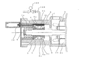
- FIG. 2 is a diagram illustrating the internal configuration of the screw compressor 102 according to Embodiment 1 of the present invention.
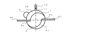
- FIG. 3 is a diagram showing the relationship between the casing 1, the screw rotor 3, the gate rotor 6, and the compression chamber 5 in the screw compressor 102 according to Embodiment 1 of the present invention.
- the screw compressor 102 according to the first embodiment of the present invention will be described with reference to FIGS. 2 and 3.
- the screw compressor 102 includes a casing 1, a screw rotor 3, a gate rotor 6, an electric motor 2 that rotationally drives the screw rotor 3, a slide valve 8, and the like.
- the cylindrical casing 1 accommodates the screw rotor 3, the gate rotor 6, the electric motor 2, the slide valve 8, and the like inside the cylinder.
- the electric motor 2 includes a stator 2a that is inscribed and fixed to the casing 1, and a motor rotor 2b that is disposed inside the stator 2a. The electric motor 2 is driven at an operation rotational speed based on the electric power supplied from the inverter device 101.
- a screw rotor 3 is disposed in the casing 1.
- the screw rotor 3 and the motor rotor 2b are disposed and fixed around the screw shaft 4 serving as a rotation shaft.
- the screw rotor 3 has a plurality of spiral screw grooves 5a formed on the outer peripheral surface thereof.
- the screw rotor 3 rotates as the motor rotor 2b fixed to the screw shaft 4 rotates.
- the screw compressor 102 according to the first embodiment has two gate rotors 6.
- the two gate rotors 6 are positions that are point-symmetric with respect to the screw shaft 4 and are respectively disposed on both sides of the screw rotor 3.
- one is a first gate rotor 6b and the other is a second gate rotor 6c.
- the gate rotor 6 has a disk shape, and a plurality of teeth 6 a are provided on the outer peripheral surface along the circumferential direction.
- the teeth 6a of the gate rotor 6 are meshed with the screw grooves 5a.
- the space surrounded by the teeth 6 a of the gate rotor 6, the screw groove 5 a and the cylinder inner surface side of the casing 1 becomes the compression chamber 5.
- a plurality of compression chambers 5 are formed at positions that are point-symmetric with respect to the radial center of the screw rotor 3.
- the compression chamber 5 surrounded by the casing 1, the screw rotor 3, and the teeth 6a of the first gate rotor 6b is referred to as a first compression chamber 5b.
- the compression chamber 5 surrounded by the casing 1, the screw rotor 3 and the teeth 6a of the second gate rotor 6c is referred to as a second compression chamber 5c.
- it demonstrates as the compression chamber 5.
- the inside of the screw compressor 102 is divided into a low pressure side which is a refrigerant suction side and a high pressure side which is a refrigerant discharge side by a partition wall (not shown).
- the space on the low-pressure side is a low-pressure chamber (not shown) that serves as a suction pressure atmosphere.
- the space on the high pressure side is a high pressure chamber (not shown) serving as a discharge pressure atmosphere.
- a discharge port 7 (see FIG. 4 to be described later) that connects the high pressure chamber and the compression chamber 5 is provided at a position on the high pressure side of the compression chamber 5.
- a slide groove 1a extending in the direction of the rotation axis of the screw rotor 3 is formed inside the casing 1 at a position corresponding to the first compression chamber 5b.
- a slide valve 8 serving as a bypass device is accommodated in the slide groove 1a so as to be slidable along the slide groove 1a.
- the slide valve 8 is integrated with the casing 1 and forms a first compression chamber 5 b together with the casing 1.
- the slide valve 8 is provided only on one compression chamber 5 side of the two compression chambers 5.
- a slide valve 8 serving as a bypass device is provided only in the first compression chamber 5b.
- the screw compressor 102 in which the slide groove 1a and the slide valve 8 are provided only on the first compression chamber 5b side will be described, but the slide groove 1a and the slide valve 8 are only on the second compression chamber 5c side. There may be. At this time, the second compression chamber 5c becomes the first compression chamber.
- the slide valve 8 is connected to a bypass drive device 10 such as a piston via a connecting rod 9.
- a bypass drive device 10 such as a piston
- the bypass control device 111 of the control device 110 has a slide valve 8 at a position where the discharge amount of fluid from the discharge port 7 of the first compression chamber 5b ⁇ the discharge amount of fluid from the discharge port of the second compression chamber 5c. Is sent to the bypass drive device 10, and the capacity control operation of the screw compressor 102 is performed.
- the bypass drive device 10 for driving the slide valve 8 does not limit the driving power source such as a device driven by gas pressure, a device driven by hydraulic pressure, and a device driven by a motor or the like separately from the piston.
- the casing 1 also has an economizer gas flow path 1b that guides the economizer gas flowing out from the intercooler 104 to the first compression chamber 5b.
- the economizer gas flow path 1b communicates with the first compression chamber 5b via the economizer port 1c.
- the economizer pipe 108 is connected to the economizer gas flow path 1b.
- the economizer gas that has flowed out of the intercooler 104 and branched and cooled the mainstream refrigerant liquid flows into the first compression chamber 5b through the economizer pipe 108, the economizer gas flow path 1b, and the economizer port 1c.
- the economizer gas flow path 1b and economizer port 1c for guiding the economizer gas from the intermediate cooler 104 communicate with the first compression chamber 5b and are provided only on the first compression chamber 5b side. Yes. Further, in the economizer gas flow path 1b in the casing 1, there is provided a space (not shown) for suppressing pulsation when the refrigerant gas flows, and there is a communication with the first compression chamber 5b via this space. .
- the screw compressor 102 sucks and compresses refrigerant gas, which is a gaseous refrigerant, and then discharges it.
- the discharge gas discharged from the screw compressor 102 is cooled by the condenser 103.
- the refrigerant cooled by the condenser 103 flows into the high-pressure side flow path of the intermediate cooler 104.
- a high-pressure side refrigerant that passes through the high-pressure side flow path, and an intermediate-pressure refrigerant that is branched after passing through the intermediate cooler 104 is decompressed by the intermediate cooler expansion valve 107, and passes through the intermediate pressure-side flow path. Heat exchanged.
- the high pressure side refrigerant is supercooled by heat exchange with the intermediate pressure refrigerant.
- the refrigeration effect in the evaporator 106 is increased.
- the supercooled refrigerant is heated by the evaporator 106 and becomes refrigerant gas.
- the refrigerant gas flowing out of the evaporator 106 is sucked into the screw compressor 102.
- the intermediate pressure refrigerant passing through the intermediate pressure side flow path of the intermediate cooler 104 becomes economizer gas after cooling the high pressure side refrigerant, and passes through the economizer pipe 108 and the economizer gas flow path 1b. Then, the economizer gas is injected from the economizer port 1c provided in the casing 1 into the first compression chamber 5b by the differential pressure between the high pressure and the intermediate pressure of the economizer gas and the pressure in the first compression chamber 5b. The injected economizer gas is mixed with the refrigerant gas being compressed and discharged from the screw compressor 102.
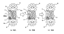
- FIG. 4 is a diagram illustrating a compression principle of the screw compressor 102 according to the first embodiment of the present invention.
- the operation of the screw compressor 102 according to Embodiment 1 will be described.
- the screw rotor 3 is rotated by the electric motor 2 shown in FIG. 2 via the screw shaft 4 shown in FIG. 2, the teeth 6a of the gate rotor 6 are compressed into the compression chamber 5 (screw groove) as shown in FIG. 5a) Move relatively within.
- a suction stroke, a compression stroke, and a discharge stroke are sequentially performed.
- the cycle is repeated with the suction stroke, compression stroke, and discharge stroke as one cycle.
- each stroke will be described.
- FIG. 4A shows the state of the compression chamber 5 in the suction stroke.
- the screw rotor 3 is driven by the electric motor 2 and rotates in the direction of the solid line arrow.
- the volume of the compression chamber 5 decreases as shown in FIG.
- the compression chamber 5 communicates with the outside through the discharge port 7 as shown in FIG. Thereby, the high-pressure refrigerant gas compressed in the compression chamber 5 is discharged from the discharge port 7 to the outside. Then, the same compression is performed again on the back surface of the screw rotor 3.
- the economizer port 1c, the slide valve 8, and the slide groove 1a are not shown.
- economizer gas flows into the compression chamber 5 through the economizer port 1c in the compression stroke. Then, the economizer gas that has flowed into the compression chamber 5 is compressed together with the refrigerant gas, and is discharged to the outside in the discharge stroke.
- the screw compressor 102 of the first embodiment is provided with the economizer port 1c only in the compression chamber 5 on one side (the first compression chamber 5b in the example of the first embodiment) to perform the economizer operation.
- the object of the economizer operation is to prevent the economizer port 1c from becoming a dead volume at the time of a low load operation that operates in a low load state. Details will be described below.
- the relationship between the suction bypass control during the high load operation and the low load operation and the relationship between the economizer port 1c and the operation during the compression stroke are compared. Will be explained.
- the low load is a predetermined load that the control device 110 uses as a criterion for determining the operation of the screw compressor 102.
- the screw compressor 102 is driven at a low rotational speed of about 20 Hz to 30 Hz or less, and the refrigerant circuit is operated at a low differential pressure.
- the low load operation is an operation at a low load.
- high load operation in general, the screw compressor 102 is driven at a high rotation speed, and the refrigerant circuit is often in a high differential pressure state.
- the compression stroke and the economizer circuit when the suction side bypass port 1d between the low pressure chamber and the compression chamber 5 is not opened in the high load operation and the compression is performed in the compression chambers 5 on both sides will be described.
- the refrigerant is compressed in the two compression chambers 5 so as not to be opened by closing the suction side bypass port 1d.
- FIG. 5 is a schematic diagram showing a state when the suction-side bypass port 1d is not open in the screw compressor 102 according to Embodiment 1 of the present invention.
- FIG. 6 is a developed view of the inner cylindrical surface of the casing 1 and the screw rotor 3 when the suction-side bypass port 1d is not open in the screw compressor 102 according to Embodiment 1 of the present invention.
- economizer operation is performed to improve the refrigeration effect and coefficient of performance.
- the bypass control device 111 of the control device 110 moves the slide valve 8 to the suction side (the right side in FIGS. 5 and 6) as indicated by the white arrows in FIGS. 5 and 6.
- the slide valve 8 is a position (first position) that prevents the suction-side bypass port 1d from being opened. Since the suction side bypass port 1d is not open, the economizer gas flow path 1b provided in the casing 1 and the first compression chamber 5b communicate with each other via the economizer port 1c, but communicate with the low pressure chamber. Absent.
- the economizer gas that has passed through the economizer gas flow path 1b is injected from the economizer port 1c into the first compression chamber 5b.
- the pressure (intermediate pressure) of the refrigerant in the first compression chamber 5b increases while the economizer port 1c is positioned in the first compression chamber 5b, the effect of expanding the capacity by the economizer operation is reduced.
- the economizer port 1c is disposed at a position where the economizer gas flows into the low pressure portion of the first compression chamber 5b as much as possible within a range that does not hinder the refrigerant gas from flowing into the compression chamber 5.
- FIG. 7 is a schematic diagram showing a state when the suction-side bypass port 1d is opened in the screw compressor 102 according to Embodiment 1 of the present invention.
- FIG. 8 is a developed view of the inner cylindrical surface of the casing 1 and the screw rotor 3 when the suction-side bypass port 1d is opened in the screw compressor 102 according to Embodiment 1 of the present invention.
- the slide valve 8 is moved to the discharge side and moved to a position where the suction side bypass port 1d of the low pressure chamber and the first compression chamber 5b is opened.
- the suction side bypass port 1d By opening the suction side bypass port 1d, the compression stroke is not performed in the first compression chamber 5b, and a no-load state is established. Since the compression stroke is performed only in the second compression chamber 5c, the excluded volume is about half (1/2) of the case where the suction side bypass port 1d is not opened.
- the driving speed is increased and driven.
- the operation speed it is possible to suppress the deterioration of the leakage ratio with respect to the discharge amount.
- the suction pressure or the pressure in the compression chamber 5 and the discharge pressure are often in a low differential pressure state. For this reason, even if the economizer is operated, the economizer effect is small. Further, the economizer gas does not easily flow into the compression chamber 5. For this reason, the economizer port 1c becomes a dead volume, resulting in recompression loss and leakage loss.
- the dead volume is a volume portion that is compressed in vain.
- the opening / closing control device 112 closes the electromagnetic valve 109 in the economizer pipe 108 to stop the economizer operation.
- the economizer port 1c and the suction side bypass port 1d are installed on the first compression chamber 5b side.
- the bypass control device 111 moves the slide valve 8 and opens the suction side bypass port 1d to perform the cylinder resting operation.
- the bypass control device 111 of the control device 110 moves the slide valve 8 to the discharge side (left side in FIGS. 7 and 8) as indicated by the white arrows in FIGS.
- the slide valve 8 is a position (second position) at which the suction-side bypass port 1d is opened. Since the first compression chamber 5b is idle, no compression stroke is performed in the first compression chamber 5b. For this reason, the economizer port 1c and the economizer gas flow path 1b cannot become dead volumes.
- the screw compressor 102 is a compressor that realizes a high coefficient of performance.
- the screw compressor 102 of the first embodiment the economizer port 1c and economizer gas flow path 1b, the suction side bypass port 1d and the slide valve 8 are provided in the first compression chamber 5b. Therefore, by opening the suction-side bypass port 1d and performing one-lung operation that can reduce the suction volume to about half, leakage loss can be reduced, and loss due to dead volume can be reduced. Can be improved. Therefore, in the refrigeration apparatus of the first embodiment, the screw compressor 102 and the refrigeration cycle apparatus 100 can obtain an economizer effect in high load operation, and can reduce dead volume loss and leakage loss in low load operation. In a wide operation range, a high coefficient of performance can be realized.
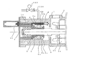
- FIG. FIG. 9 is a diagram illustrating a configuration of the refrigeration cycle apparatus 100 including the screw compressor 102 according to Embodiment 2 of the present invention. Here, a different part from the refrigerating-cycle apparatus 100 of Embodiment 1 is demonstrated.
- the refrigeration cycle apparatus 100 of the second embodiment is different from the refrigeration cycle apparatus 100 of the first embodiment in the configuration of the screw compressor 102 and the control device 110.
- the screw compressor 102 in the second embodiment has a first slide valve 8a and a second slide valve 8b.
- the first slide valve 8a is installed in the first compression chamber 5b.
- the first slide valve 8a operates as a bypass device in the same manner as the slide valve 8 described in the first embodiment.
- the screw compressor 102 according to the second embodiment is not limited to the first compression chamber 5b side but also the second compression chamber 5c side as compared with the screw compressor 102 according to the first embodiment.
- the second slide valve 8 b is installed so as to be movable in the axial direction of the screw rotor 3.
- an internal volume ratio variable mechanism 11 for changing the position of the second slide valve 8b is installed.
- the internal volume ratio is a ratio between the volume of the compression chamber 5 at the completion of suction (compression start) and the volume of the compression chamber 5 just before the discharge. The internal volume ratio is changed by adjusting the timing at which the refrigerant is discharged from the discharge port 7.
- the second slide valve 8b is positioned on the suction side, and the position is changed so that the opening timing of the discharge port 7 is advanced and the volume ratio is reduced. Further, during high load operation, the second slide valve 8b is positioned on the discharge side, and the position is changed so as to increase the volume ratio by delaying the opening timing of the discharge port 7.
- the second slide valve 8b constitutes a part of the discharge port 7.
- the internal volume ratio variable mechanism 11 moves the second slide valve 8b, thereby adjusting the discharge timing and changing the internal volume ratio. Therefore, under-compression during high-load operation and over-compression during low-load operation are suppressed, and performance is improved.
- control device 110 of the second embodiment further includes an internal volume ratio control device 113.
- the internal volume ratio control device 113 sends an instruction to the internal volume ratio variable mechanism 11 and performs control to position the second slide valve 8b based on the internal volume ratio.
- the position control and the economizer port 1c of the first slide valve 8a and the second slide valve 8b during the high load operation and the low load operation are performed as in the first embodiment.
- the operation during the compression stroke will be described in comparison with the above relationship.
- FIG. 10 is a schematic diagram showing a state when the suction-side bypass port 1d is not open in the screw compressor 102 according to Embodiment 2 of the present invention.
- FIG. 11 is a developed view of the inner cylindrical surface of the casing 1 and the screw rotor 3 when the suction-side bypass port 1d is not open in the screw compressor 102 according to Embodiment 2 of the present invention. Based on FIG. 10 and FIG. 11, the operation
- the bypass control device 111 of the control device 110 moves the first slide valve 8a to the suction side (FIG. 10) as indicated by the white arrows in FIGS. And the right side in FIG.
- the first slide valve 8a is a position (first position) where the suction side bypass port 1d is not opened.
- the internal volume ratio control device 113 of the control device 110 sends an instruction to the internal volume ratio variable mechanism 11 so that the internal volume ratio is the same in the first compression chamber 5b and the second compression chamber 5c, and the refrigerant is discharged from the discharge port 7.
- the second slide valve 8b is positioned so that the timings of discharging are the same. Specifically, as indicated by the white arrows in FIGS. 10 and 11, for example, the second slide valve 8b is moved to the discharge side (left side in FIGS. 10 and 11).
- two compression chambers 5 are formed in the screw compressor 102 by not opening the suction-side bypass port 1d that communicates the low pressure chamber and the first compression chamber 5b. And since economizer gas flows in into the 1st compression chamber 5b via economizer piping 108 etc., the refrigerating capacity required at the time of high load operation can be secured. Furthermore, a high coefficient of performance can be realized by adjusting the economizer effect and the internal volume ratio so as to be in proper positions.
- FIG. 12 is a schematic diagram showing a state when the suction-side bypass port 1d is opened in the screw compressor 102 according to Embodiment 2 of the present invention.
- FIG. 13 is a developed view of the inner cylindrical surface of the casing 1 and the screw rotor 3 when the suction-side bypass port 1d is opened in the screw compressor 102 according to Embodiment 2 of the present invention.
- the economizer operation is not performed under the operation condition of low load. Therefore, the opening / closing control device 112 of the control device 110 closes the electromagnetic valve 109 so that the economizer gas does not flow into the first compression chamber 5b.
- the bypass control device 111 of the control device 110 moves the slide valve 8 to the discharge side (left side in FIGS. 12 and 13) as indicated by the white arrows in FIGS.
- the slide valve 8 is a position (second position) at which the suction-side bypass port 1d is opened. Since the first compression chamber 5b is idle, no compression stroke is performed in the first compression chamber 5b.
- the internal volume ratio control device 113 of the control device 110 sends an instruction to the internal volume ratio variable mechanism 11 to move the second slide valve 8b to a position suitable for operation. Specifically, as indicated by the white arrows in FIGS. 12 and 13, for example, the second slide valve 8 b is moved to the suction side (the right side in FIGS. 12 and 13), which is a direction to reduce the internal volume ratio. .
- the screw compressor 102 of the second embodiment the economizer port 1c and the economizer gas flow path 1b in the state where the first slide valve 8a is moved and the suction side bypass port 1d is opened. Is formed in the first compression chamber 5b where the suction side bypass port 1d is opened. For this reason, one-lung operation can be performed even during low-load operation, and the effect of suppressing leakage loss can be ensured by increasing the operation speed. And since it is not influenced by the space used as a dead volume, recompression loss and leakage loss can be reduced. Therefore, the screw compressor 102 of Embodiment 2 can obtain the screw compressor 102 that achieves a high coefficient of performance.
- the internal volume ratio in the second compression chamber 5c is set appropriately. be able to. For this reason, power loss due to under-compression and over-compression can be suppressed, and a higher coefficient of performance can be realized over a wide operating range.
- Embodiment 3 FIG.
- the control related to the movement of the second slide valve 8b in the screw compressor 102 performed by the control device 110 may be continuous or stepwise. May be.
Landscapes
- Engineering & Computer Science (AREA)
- Mechanical Engineering (AREA)
- General Engineering & Computer Science (AREA)
- Physics & Mathematics (AREA)
- Thermal Sciences (AREA)
- Applications Or Details Of Rotary Compressors (AREA)
Abstract
Priority Applications (3)
| Application Number | Priority Date | Filing Date | Title |
|---|---|---|---|
| PCT/JP2016/056265 WO2017149659A1 (fr) | 2016-03-01 | 2016-03-01 | Compresseur à vis et dispositif à cycle de réfrigération |
| JP2018502908A JP6685379B2 (ja) | 2016-03-01 | 2016-03-01 | スクリュー圧縮機および冷凍サイクル装置 |
| EP16892504.8A EP3425202B1 (fr) | 2016-03-01 | 2016-03-01 | Compresseur à vis et dispositif à cycle de réfrigération |
Applications Claiming Priority (1)
| Application Number | Priority Date | Filing Date | Title |
|---|---|---|---|
| PCT/JP2016/056265 WO2017149659A1 (fr) | 2016-03-01 | 2016-03-01 | Compresseur à vis et dispositif à cycle de réfrigération |
Publications (1)
| Publication Number | Publication Date |
|---|---|
| WO2017149659A1 true WO2017149659A1 (fr) | 2017-09-08 |
Family
ID=59743579
Family Applications (1)
| Application Number | Title | Priority Date | Filing Date |
|---|---|---|---|
| PCT/JP2016/056265 Ceased WO2017149659A1 (fr) | 2016-03-01 | 2016-03-01 | Compresseur à vis et dispositif à cycle de réfrigération |
Country Status (3)
| Country | Link |
|---|---|
| EP (1) | EP3425202B1 (fr) |
| JP (1) | JP6685379B2 (fr) |
| WO (1) | WO2017149659A1 (fr) |
Cited By (7)
| Publication number | Priority date | Publication date | Assignee | Title |
|---|---|---|---|---|
| CN107461222A (zh) * | 2017-09-13 | 2017-12-12 | 北京工业大学 | 一种集成滑阀的单螺杆膨胀机 |
| CN108644116A (zh) * | 2018-07-13 | 2018-10-12 | 麦克维尔空调制冷(苏州)有限公司 | 螺杆压缩机系统以及包含该螺杆压缩机系统的换热系统 |
| GB2581526A (en) * | 2019-02-22 | 2020-08-26 | J & E Hall Ltd | Single screw compressor |
| WO2021229743A1 (fr) * | 2020-05-14 | 2021-11-18 | 三菱電機株式会社 | Compresseur à vis |
| CN114729639A (zh) * | 2019-11-26 | 2022-07-08 | 三菱电机株式会社 | 螺杆式压缩机 |
| WO2022244219A1 (fr) * | 2021-05-21 | 2022-11-24 | 三菱電機株式会社 | Compresseur à vis |
| WO2026058422A1 (fr) * | 2024-09-13 | 2026-03-19 | 三菱電機株式会社 | Compresseur à vis et dispositif à cycle frigorifique |
Families Citing this family (2)
| Publication number | Priority date | Publication date | Assignee | Title |
|---|---|---|---|---|
| CN109854509B (zh) * | 2019-03-19 | 2024-04-26 | 福建雪人股份有限公司 | 一种燃料电池用空气压缩机的内建容积比的自动调节装置 |
| US12546316B1 (en) * | 2024-08-07 | 2026-02-10 | Copeland Industrial Lp | Low ratio oil injection port for applications without the requirement of an oil pump |
Citations (5)
| Publication number | Priority date | Publication date | Assignee | Title |
|---|---|---|---|---|
| JPH0510614A (ja) * | 1991-07-02 | 1993-01-19 | Daikin Ind Ltd | スクリユー冷凍装置 |
| JPH076509B2 (ja) * | 1985-06-03 | 1995-01-30 | ヴィルタ−・マニュファクチャリング・コ−ポレ−ション | 二重すべり弁を有する気体圧縮機 |
| JP2012107613A (ja) * | 2010-10-29 | 2012-06-07 | Daikin Industries Ltd | スクリュー圧縮機 |
| US20140083130A1 (en) * | 2012-09-27 | 2014-03-27 | Vilter Manufacturing Llc | Apparatus and Method for Enhancing Compressor Efficiency |
| WO2014192898A1 (fr) * | 2013-05-30 | 2014-12-04 | 三菱電機株式会社 | Compresseur à vis et dispositif de cycle de réfrigération |
Family Cites Families (5)
| Publication number | Priority date | Publication date | Assignee | Title |
|---|---|---|---|---|
| JP4374958B2 (ja) * | 2003-09-16 | 2009-12-02 | ダイキン工業株式会社 | シングルスクリュー圧縮機 |
| US8858192B2 (en) * | 2009-03-16 | 2014-10-14 | Daikin Industries, Ltd. | Screw compressor |
| JP5445118B2 (ja) * | 2009-12-24 | 2014-03-19 | ダイキン工業株式会社 | スクリュー圧縮機 |
| CN105247216B (zh) * | 2013-05-30 | 2017-05-17 | 三菱电机株式会社 | 螺杆式压缩机和冷冻循环装置 |
| WO2016046908A1 (fr) * | 2014-09-24 | 2016-03-31 | 三菱電機株式会社 | Compresseur en forme de vis et dispositif à cycle de réfrigération |
-
2016
- 2016-03-01 EP EP16892504.8A patent/EP3425202B1/fr active Active
- 2016-03-01 WO PCT/JP2016/056265 patent/WO2017149659A1/fr not_active Ceased
- 2016-03-01 JP JP2018502908A patent/JP6685379B2/ja active Active
Patent Citations (5)
| Publication number | Priority date | Publication date | Assignee | Title |
|---|---|---|---|---|
| JPH076509B2 (ja) * | 1985-06-03 | 1995-01-30 | ヴィルタ−・マニュファクチャリング・コ−ポレ−ション | 二重すべり弁を有する気体圧縮機 |
| JPH0510614A (ja) * | 1991-07-02 | 1993-01-19 | Daikin Ind Ltd | スクリユー冷凍装置 |
| JP2012107613A (ja) * | 2010-10-29 | 2012-06-07 | Daikin Industries Ltd | スクリュー圧縮機 |
| US20140083130A1 (en) * | 2012-09-27 | 2014-03-27 | Vilter Manufacturing Llc | Apparatus and Method for Enhancing Compressor Efficiency |
| WO2014192898A1 (fr) * | 2013-05-30 | 2014-12-04 | 三菱電機株式会社 | Compresseur à vis et dispositif de cycle de réfrigération |
Non-Patent Citations (1)
| Title |
|---|
| See also references of EP3425202A4 * |
Cited By (11)
| Publication number | Priority date | Publication date | Assignee | Title |
|---|---|---|---|---|
| CN107461222A (zh) * | 2017-09-13 | 2017-12-12 | 北京工业大学 | 一种集成滑阀的单螺杆膨胀机 |
| CN108644116A (zh) * | 2018-07-13 | 2018-10-12 | 麦克维尔空调制冷(苏州)有限公司 | 螺杆压缩机系统以及包含该螺杆压缩机系统的换热系统 |
| WO2020011126A1 (fr) * | 2018-07-13 | 2020-01-16 | 麦克维尔空调制冷(苏州)有限公司 | Système de compresseur à vis et système d'échange de chaleur comprenant un système de compresseur à vis |
| GB2581526A (en) * | 2019-02-22 | 2020-08-26 | J & E Hall Ltd | Single screw compressor |
| JP2022521338A (ja) * | 2019-02-22 | 2022-04-06 | ジェイ アンド イー ホール リミテッド | シングルスクリュー圧縮機 |
| US12158147B2 (en) | 2019-02-22 | 2024-12-03 | Daikin Industries, Ltd. | Slide valve of a single screw compressor |
| JP7777449B2 (ja) | 2019-02-22 | 2025-11-28 | ダイキン工業株式会社 | シングルスクリュー圧縮機 |
| CN114729639A (zh) * | 2019-11-26 | 2022-07-08 | 三菱电机株式会社 | 螺杆式压缩机 |
| WO2021229743A1 (fr) * | 2020-05-14 | 2021-11-18 | 三菱電機株式会社 | Compresseur à vis |
| WO2022244219A1 (fr) * | 2021-05-21 | 2022-11-24 | 三菱電機株式会社 | Compresseur à vis |
| WO2026058422A1 (fr) * | 2024-09-13 | 2026-03-19 | 三菱電機株式会社 | Compresseur à vis et dispositif à cycle frigorifique |
Also Published As
| Publication number | Publication date |
|---|---|
| EP3425202A4 (fr) | 2019-01-09 |
| EP3425202B1 (fr) | 2024-06-19 |
| JP6685379B2 (ja) | 2020-04-22 |
| JPWO2017149659A1 (ja) | 2018-09-20 |
| EP3425202A1 (fr) | 2019-01-09 |
Similar Documents
| Publication | Publication Date | Title |
|---|---|---|
| JP6685379B2 (ja) | スクリュー圧縮機および冷凍サイクル装置 | |
| JP6177449B2 (ja) | スクリュー圧縮機および冷凍サイクル装置 | |
| CN103620224B (zh) | 回转式压缩机 | |
| CN105247217B (zh) | 螺杆压缩机和冷冻循环装置 | |
| CN109154455B (zh) | 制冷循环装置 | |
| WO2021200858A1 (fr) | Compresseur à vis et dispositif de réfrigération | |
| JP5228905B2 (ja) | 冷凍装置 | |
| CN107614879A (zh) | 螺杆压缩机及具备该螺杆压缩机的制冷循环装置 | |
| JP5951125B2 (ja) | スクリュー圧縮機及び冷凍サイクル装置 | |
| JP6234611B2 (ja) | スクリュー圧縮機および冷凍サイクル装置 | |
| WO2017094057A1 (fr) | Compresseur à vis unique et dispositif à cycle de réfrigération | |
| JP6177450B2 (ja) | スクリュー圧縮機および冷凍サイクル装置 | |
| WO2018131089A1 (fr) | Dispositif à cycle de réfrigération | |
| JP7158603B2 (ja) | スクリュー圧縮機 | |
| JP2016017465A (ja) | シングルスクリュー圧縮機 | |
| WO2017203642A1 (fr) | Compresseur à vis et dispositif à cycle de réfrigération | |
| WO2017175298A1 (fr) | Compresseur à vis et dispositif à cycle de réfrigération | |
| WO2020026333A1 (fr) | Compresseur à vis et dispositif à cycle frigorifique | |
| JP2013238135A (ja) | スクリュー圧縮機 | |
| JP5321055B2 (ja) | 冷凍装置 | |
| WO2025074558A1 (fr) | Compresseur à vis et dispositif à cycle frigorifique | |
| JP6915398B2 (ja) | 圧縮機 | |
| WO2023162744A1 (fr) | Compresseur à vis et dispositif de réfrigration | |
| JP2024146834A (ja) | スクリュー圧縮機及び冷凍装置 | |
| WO2016088207A1 (fr) | Circuit de cycle de réfrigération |
Legal Events
| Date | Code | Title | Description |
|---|---|---|---|
| ENP | Entry into the national phase |
Ref document number: 2018502908 Country of ref document: JP Kind code of ref document: A |
|
| NENP | Non-entry into the national phase |
Ref country code: DE |
|
| WWE | Wipo information: entry into national phase |
Ref document number: 2016892504 Country of ref document: EP |
|
| ENP | Entry into the national phase |
Ref document number: 2016892504 Country of ref document: EP Effective date: 20181001 |
|
| 121 | Ep: the epo has been informed by wipo that ep was designated in this application |
Ref document number: 16892504 Country of ref document: EP Kind code of ref document: A1 |